EP0517696B1 - Bath seat - Google Patents
Bath seat Download PDFInfo
- Publication number
- EP0517696B1 EP0517696B1 EP90911093A EP90911093A EP0517696B1 EP 0517696 B1 EP0517696 B1 EP 0517696B1 EP 90911093 A EP90911093 A EP 90911093A EP 90911093 A EP90911093 A EP 90911093A EP 0517696 B1 EP0517696 B1 EP 0517696B1
- Authority
- EP
- European Patent Office
- Prior art keywords
- seat
- baby
- base
- bath
- top portion
- Prior art date
- Legal status (The legal status is an assumption and is not a legal conclusion. Google has not performed a legal analysis and makes no representation as to the accuracy of the status listed.)
- Expired - Lifetime
Links
Images


Classifications
-
- A—HUMAN NECESSITIES
- A47—FURNITURE; DOMESTIC ARTICLES OR APPLIANCES; COFFEE MILLS; SPICE MILLS; SUCTION CLEANERS IN GENERAL
- A47K—SANITARY EQUIPMENT; ACCESSORIES THEREFOR, e.g. TOILET ACCESSORIES
- A47K3/00—Baths; Showers; Appurtenances therefor
- A47K3/12—Separate seats or body supports
- A47K3/125—Body supports
- A47K3/127—Body supports for children or babies
-
- A—HUMAN NECESSITIES
- A47—FURNITURE; DOMESTIC ARTICLES OR APPLIANCES; COFFEE MILLS; SPICE MILLS; SUCTION CLEANERS IN GENERAL
- A47K—SANITARY EQUIPMENT; ACCESSORIES THEREFOR, e.g. TOILET ACCESSORIES
- A47K3/00—Baths; Showers; Appurtenances therefor
- A47K3/12—Separate seats or body supports
- A47K3/122—Seats
Definitions
- This invention relates to bath seats and is more particularly concerned with a bath seat for infants.
- Such a device is shown in US-A-2,645,781 and is provided with a backrest having suction cups and a harness to be affixed to the infant to restrain it from sliding into the water, while supporting the child's head.
- Bathing chairs have also been proposed with adjustable backrests such as shown in US-A-3,086,222, the backrest being slidable into several extended positions.
- US-A-3,619,823 discloses a baby shower-bath and play tub.
- CA-A-1065556 discloses a baby bath seat adapted to be positioned, in use, on the bottom of a bath tub which comprises a base with a seat rotatably mounted thereon by cooperating means. This seat is designed to position the seat in an elevated position in the bath tub so the person using the seat cannot be immersed in the water in the tub.
- US-A-2,701,006 discloses a baby bath seat comprising the features defined in the preamble of independent claim 1.
- None of these prior art devices propose a simple bath seat which not only provides back support but also is positionable rotationally in the bath tub whereby the person bathing the child can reposition the child and secure the relative position of the seat in order to more easily bathe the child.
- a further object of the invention is to provide a positionable bath seat for infants within a bath tub which enables the repositioning of the infant while sitting within the device in different relative positions with respect to the tub for ease in bathing.
- a preferred embodiment of the invention is to provide a positionable baby bath seat wherein the relative rotational position of the seat with respect to the bath tub surface is adjustable and retainable in the adjusted position.
- the present invention overcomes the problems of the prior art by providing a baby bath seat characterised by the features defined in the characterising part of independent claim 1.
- the bath seat of the invention comprises three portions, namely a top portion 2 of generally circular configuration, an intermediate portion 4 and a complementary base portion 6, both being of circular configuration. All three elements may be made of molded plastic.
- the circular base portion 6 is held in an immobile position relative to a bath tub by means of the suction cups 8, 10 and 12. These suction cups are provided with respective release tabs 14, 16 and 18 in order to release the suction when it is desired to remove the bath seat from the bath tub.
- suction cup is formed in the same manner and therefore only one of such suction cups will be described in more detail.
- suction cup 10 comprises a concave suction cup element of resilient material which has a central hub 20, a reduced diameter portion 22 and a retention head 24.
- the retention head 24 upon assembly will be positioned above a base member base plate 130, after passing through an opening in that base plate wherein the reduced diameter portion 22 will be accommodated.
- the intermediate portion 4 is provided with a series of support posts 30, 32 and 34 to position the top portion at a distance from a contoured seat 76 to accommodate the infant.
- the support posts may be of the same length.
- the top portion is configured so that there is a backrest or back support 46, sidearm supports 48 and 50, and a front section 52 which is somewhat elevated.
- the front post 32 will not quite reach the U-shaped frame 44 and therefore will have a reduced section 42 enabling snap fit assembly to a female receptacle 40.
- the other posts 30 and 34 are assembled to the top portion 2 into receptacles (not shown), similar in nature to 40 but within the U-shaped frame 44, and not extending therebelow.
- the front section 52 is provided with a pair of tray recesses 54 and 56 molded therein, and the rear section or back support 46 is provided with a carrying handle 58 which also is formed in a mold.
- the front section is provided with a center opening 60 to accommodate a toy element.
- the opening 60 is provided by sidewalls 62 and 64. These sidewalls accommodate a cross-shaped axle 66, and as shown in Figure 1A this axle snap fits into a recess 68 in sidewall 62 and a similar opening in sidewall 64.
- Mounted on the axle 66 are one or more roller beads 70, 72 and 74 which can be multicolored and are free to rotate.
- the intermediate body portion 4 is provided with the contoured seat 76 and a U-shaped rim 78 which is in turn provided with a lower lip 80.
- This rim 78 mates with a lip 88 on the base member 6 by having its lip 80 snap fit over lip 88 as more clearly shown in Figure 6 to provide the relative rotational capability between base member 6 and intermediate member 4, and to retain member 4 to base 6.
- a detent mechanism is provided which enables retaining the intermediate portion 4 in a desired rotational position with respect to base 6 and has the ability when desired to permit relative rotational motion therebetween.
- This detention means comprises a knob 82 which has a protruding operating lever 84. If desired, the relative dimensions of the parts can be such that they fit very snugly and the knob 82 can be positioned by the lever 84 and retained in any position between the limits of the opening 92 in the intermediate portion 4 because of the snug fit. In this manner, the depending teeth 112 of the knob 82 can be positioned to either be vertically extending as shown in Figure 6 or at an angle to the vertical as shown in Figure 4.
- the knob is provided with stub shafts 102 and 104 which are snap fit into assembled position into the recesses such as 97 in the side depending walls 94, 96 of the intermediate member 4.
- torsion springs may be provided for the knob 82 so as to provide bias to urge it into a desired "normal" position.
- These springs 90, 91 are positioned one at each end of the knob 82.
- the torsion springs have legs 93 and 95 which are retained between a post 98 or 100 on the side walls 94, 96, respectively and a pin on the knob such as pin 86 shown in Figure 6.
- a similar pin would be provided for the opposite aide of the knob 82.
- Figure 6 shows the knob 82 in the released position as indicated by the force arrow acting on operating lever 84.
- the spring/pin arrangement can be such to operate either to provide a normal positioning of the depending teeth 112 so that they are in engagement with a series of upstanding walls or lugs 114 on base 6, or normally in disengagement therewith.
- the arrangement shown in Figures 6 & 7 provides that the normal position of the depending teeth 112 on the body 110, which is generally of cylindrical nature, would be as shown in Figure 4.
- the lever 84 is in its lowermost position against one extremity of the opening 92, and the teeth 112 are in engagement with one or more upstanding walls or lugs 114 in the base 6.
- a plurality of teeth 112 depend from the cylindrical body 110 (five being shown). These teeth have a tapered forward surface such as provided by the tapered surfaces 118, 120 (see Figure 7).
- the cylindrical body 110 is cut away at 116 and is formed into the series of teeth 112 and to provide a recess so that when the teeth 112 are vertically positioned they will not interfere with the lugs 114.
- the lugs 114 similarly have tapered surfaces 122 and 124 to allow for slight misalignment of the parts when positioning the teeth 112 into mating position with the lugs 114.
- the base plate 130 of the base portion 6 is formed with a hollowed center which has a central hub 140 and structural reinforcement ribs 132, 134, 136 and 138.
- a raised boss or rib 142 is provided in the base plate 130 adjacent the edge 144 of base plate 130.
Landscapes
- Health & Medical Sciences (AREA)
- Public Health (AREA)
- Epidemiology (AREA)
- General Health & Medical Sciences (AREA)
- Child & Adolescent Psychology (AREA)
- Seats For Vehicles (AREA)
- Devices For Medical Bathing And Washing (AREA)
- Bathtubs, Showers, And Their Attachments (AREA)
- Glass Compositions (AREA)
- Percussion Or Vibration Massage (AREA)
- Chairs Characterized By Structure (AREA)
- Special Chairs (AREA)
Abstract
Description
- This invention relates to bath seats and is more particularly concerned with a bath seat for infants.
- Many devices have been proposed to be used for supporting children in a bathtub in connection with their bathing. In particular, such devices have consisted simply of a bath ring which has suction cups enabling it to be mounted securely within, and to be readily removable from a bath tub. Such devices are shown for example in US Design Patent Nos. 284,690 and 288,118. Although devices of a simple ring structure are adequate for aiding children who are able to sit up unaided, bath seats have been proposed which allow the child to be secured so that the hands of the person bathing the child are both free while the child is held securely. Such a device is shown in US-A-2,645,781 and is provided with a backrest having suction cups and a harness to be affixed to the infant to restrain it from sliding into the water, while supporting the child's head. Bathing chairs have also been proposed with adjustable backrests such as shown in US-A-3,086,222, the backrest being slidable into several extended positions. US-A-3,619,823 discloses a baby shower-bath and play tub.
- CA-A-1065556 discloses a baby bath seat adapted to be positioned, in use, on the bottom of a bath tub which comprises a base with a seat rotatably mounted thereon by cooperating means. This seat is designed to position the seat in an elevated position in the bath tub so the person using the seat cannot be immersed in the water in the tub.
- US-A-2,701,006 discloses a baby bath seat comprising the features defined in the preamble of independent claim 1.
- None of these prior art devices propose a simple bath seat which not only provides back support but also is positionable rotationally in the bath tub whereby the person bathing the child can reposition the child and secure the relative position of the seat in order to more easily bathe the child.
- It is therefore one object of the invention to provide a bath seat for children in which a substantially rigid back support is provided while allowing for repositioning of the seat with respect to its base.
- A further object of the invention is to provide a positionable bath seat for infants within a bath tub which enables the repositioning of the infant while sitting within the device in different relative positions with respect to the tub for ease in bathing.
- A preferred embodiment of the invention is to provide a positionable baby bath seat wherein the relative rotational position of the seat with respect to the bath tub surface is adjustable and retainable in the adjusted position.
- The present invention overcomes the problems of the prior art by providing a baby bath seat characterised by the features defined in the characterising part of independent claim 1.
- Various modifications of the baby bath seat claimed in claim 1 are defined in the
dependent claims 2 to 20. - A preferred embodiment of the invention will now be described, by way of example only, with reference to the accompanying drawings, in which:
- FIGURE 1 is a perspective view of the bath seat of the invention;
- FIGURE 1A is an enlarged partial cross sectional view of the front section of the top portion of the bath seat taken along
line 1A-1A of Figure 1; - FIGURE 2 is a front elevational view of the bath seat of Figure 1;
- FIGURE 3 is a rear elevational view of the bath seat of Figure 1;
- FIGURE 4 is a cross sectional view taken along line 4-4 of Figure 3;
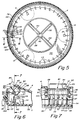
- FIGURE 5 is a cross sectional view taken along line 5-5 of Figure 4;
- FIGURE 6 is a cross sectional view taken along line 6-6 of Figure 5, but with the operating knob in the released position; and
- FIGURE 7 is a cross sectional view taken along line 7-7 of Figure 6.
- Referring to Figures 1-3, the bath seat of the invention comprises three portions, namely a
top portion 2 of generally circular configuration, anintermediate portion 4 and acomplementary base portion 6, both being of circular configuration. All three elements may be made of molded plastic. Thecircular base portion 6 is held in an immobile position relative to a bath tub by means of thesuction cups respective release tabs suction cup 10 comprises a concave suction cup element of resilient material which has acentral hub 20, a reduceddiameter portion 22 and aretention head 24. As shown in Figure 5, for example, theretention head 24 upon assembly will be positioned above a basemember base plate 130, after passing through an opening in that base plate wherein the reduceddiameter portion 22 will be accommodated. - The
intermediate portion 4 is provided with a series ofsupport posts seat 76 to accommodate the infant. The support posts may be of the same length. The top portion is configured so that there is a backrest orback support 46, sidearm supports 48 and 50, and afront section 52 which is somewhat elevated. Thefront post 32 will not quite reach the U-shapedframe 44 and therefore will have a reducedsection 42 enabling snap fit assembly to afemale receptacle 40. Theother posts top portion 2 into receptacles (not shown), similar in nature to 40 but within theU-shaped frame 44, and not extending therebelow. - The
front section 52 is provided with a pair oftray recesses back support 46 is provided with acarrying handle 58 which also is formed in a mold. - The front section is provided with a center opening 60 to accommodate a toy element. The opening 60 is provided by
sidewalls cross-shaped axle 66, and as shown in Figure 1A this axle snap fits into arecess 68 insidewall 62 and a similar opening insidewall 64. Mounted on theaxle 66 are one ormore roller beads - The
intermediate body portion 4 is provided with thecontoured seat 76 and a U-shapedrim 78 which is in turn provided with alower lip 80. This rim 78 mates with alip 88 on thebase member 6 by having itslip 80 snap fit overlip 88 as more clearly shown in Figure 6 to provide the relative rotational capability betweenbase member 6 andintermediate member 4, and to retainmember 4 tobase 6. - A detent mechanism is provided which enables retaining the
intermediate portion 4 in a desired rotational position with respect tobase 6 and has the ability when desired to permit relative rotational motion therebetween. This detention means comprises aknob 82 which has a protrudingoperating lever 84. If desired, the relative dimensions of the parts can be such that they fit very snugly and theknob 82 can be positioned by thelever 84 and retained in any position between the limits of theopening 92 in theintermediate portion 4 because of the snug fit. In this manner, the dependingteeth 112 of theknob 82 can be positioned to either be vertically extending as shown in Figure 6 or at an angle to the vertical as shown in Figure 4. - The knob is provided with
stub shafts side depending walls intermediate member 4. Alternatively, torsion springs may be provided for theknob 82 so as to provide bias to urge it into a desired "normal" position. Thesesprings knob 82. As more clearly shown in Figures 6 and 7, the torsion springs havelegs post 98 or 100 on theside walls pin 86 shown in Figure 6. A similar pin would be provided for the opposite aide of theknob 82. Figure 6 shows theknob 82 in the released position as indicated by the force arrow acting onoperating lever 84. Again, the spring/pin arrangement can be such to operate either to provide a normal positioning of the dependingteeth 112 so that they are in engagement with a series of upstanding walls orlugs 114 onbase 6, or normally in disengagement therewith. The arrangement shown in Figures 6 & 7 provides that the normal position of the dependingteeth 112 on thebody 110, which is generally of cylindrical nature, would be as shown in Figure 4. In this figure, thelever 84 is in its lowermost position against one extremity of theopening 92, and theteeth 112 are in engagement with one or more upstanding walls orlugs 114 in thebase 6. As shown in Figure 7, a plurality ofteeth 112 depend from the cylindrical body 110 (five being shown). These teeth have a tapered forward surface such as provided by thetapered surfaces 118, 120 (see Figure 7). Thecylindrical body 110 is cut away at 116 and is formed into the series ofteeth 112 and to provide a recess so that when theteeth 112 are vertically positioned they will not interfere with thelugs 114. - The
lugs 114 similarly havetapered surfaces teeth 112 into mating position with thelugs 114. - The
base plate 130 of thebase portion 6 is formed with a hollowed center which has acentral hub 140 andstructural reinforcement ribs intermediate body 4 andbase 6, a raised boss orrib 142 is provided in thebase plate 130 adjacent theedge 144 ofbase plate 130. - What has been shown and described is a bath seat in a preferred embodiment. It will be readily understood by those skilled in the art that various modifications and rearrangements of parts may be accomplished without departing from the scope of the invention as defined in the claims.
Claims (20)
- A baby bath seat comprising a base (6) adapted to be positioned, in use, on the bottom of a bath tub with a seat (76) mounted and supported thereon by cooperating means (78,80), the seat further including a rigid top portion (2) disposed above and spaced from the seat for substantially encircling the body of the baby when seated on the seat (76) and spaced from the seat (76) by support means (30,32,34) characterised in that the support means (30,32,34) provide openings therebetween to receive the legs of the baby, the seat (76) being rotatably mounted on the base (6) and the base (6) including means (8,10,12) supporting the baby bath seat on and closely adjacent to the bottom of the bath, whereby, in use, a baby positioned on the seat will be disposed substantially within the tub below the top edge thereof.
- A baby bath seat as claimed in claim 1 characterised in that the openings extend fully between the seat (76) and the top portion (2).
- A baby bath seat as claimed in claim 1 or claim 2 characterised in that the support means (8,10,12) on the base (6) releasably secure the base (6) to the bottom of the bath tub.
- A baby bath seat as claimed in any preceding claim characterised in that the top portion (2) includes a back support (46) for a baby seated on the seat.
- A baby bath seat as claimed in any preceding claim characterised in that the openings are large open areas between the seat (76) and the top portion (2) to provide access to the baby's body for washing while the baby is seated on the seat.
- A baby bath seat as claimed in any preceding claim characterised in that latching means is connected between the seat (76) and base (6) for enabling the seat to be rotated on and be releasably locked in a plurality of selected positions relative to the base.
- A baby bath seat as claimed in claim 6 wherein the base (6) and seat (76) define an enclosed chamber between them and the latching means is disposed in the chamber.
- A baby bath seat as claimed in any preceding claim characterised in that the seat is contoured.
- A baby bath seat as claimed in any preceding claim characterised in that the top portion has armrests (48,50) for a baby seated on the seat.
- A baby bath seat as claimed in any preceding claim characterised in that the support means comprise a plurality of posts (30,32,34) extending from the seat to the top portion, one post (32) being located to be disposed between the baby's legs to prevent the baby from sliding out of the seat.
- A baby bath seat as claimed in any of claims 3-10 characterised in that the means for releasably securing the base (6) to the bottom of the tub are suction cups (8,10,12).
- A baby bath seat as claimed in any preceding claim characterised in that the top portion (2) is provided with a tray surface (54,56).
- A baby bath seat as claimed in any preceding claim characterised in that the top portion (2) is provided with a toy which is normally inseparable therefrom.
- A baby bath seat as claimed in claim 13 characterised in that the toy comprises at least one bead (70,72,74) rotatably mounted on the front of the top portion (2).
- A bath seat as claimed in any preceding claim characterised in that the seat (76) and base (6) are generally of circular configuration as viewed in plan view, and the cooperating means comprises a pair of inter-engaging surfaces (78,80), one surface on the seat and a complimentary mating surface on the base.
- A bath seat as claimed in any preceding claim characterised in that the cooperating means includes detention means operable to prevent relative motion in one position and permit relative motion in another position.
- A bath seat as claimed in claim 16 characterised in that said detention means (78,80) includes a plurality of abutment surfaces on one of said base (6) and seat (76) and a movable detent (112) on the other of said base (6) and seat (76) arranged to selectively engage at least one of the abutment surfaces, and wherein the abutment surfaces comprise a plurality of discrete wall elements (114) on one of said base or seat extending towards the other one of said base (6) or seat (76), and the seat (76) or base (6) not having the wall elements being provided with a movable detent (112) positionable to engage at least one of said discrete wall elements (114) to prevent said relative motion.
- A bath seat as claimed in claim 17 characterised in that the movable detent is provided with a series of teeth (112) which are positionable to engage one or more discrete wall elements (114).
- A bath seat as claimed in claim 18 characterised in that the detent (112) is provided with an operating lever (84).
- A bath seat as claimed in claim 17 wherein the base (6) is provided with suction cup means (8,10,12) enabling the affixing of said base (6) to a surface in an immobile position with respect thereto.
Applications Claiming Priority (3)
| Application Number | Priority Date | Filing Date | Title |
|---|---|---|---|
| US485619 | 1983-04-18 | ||
| US07/485,619 US5010606A (en) | 1990-02-27 | 1990-02-27 | Bath seat |
| PCT/US1990/003520 WO1991012759A1 (en) | 1990-02-27 | 1990-06-20 | Bath seat |
Publications (3)
| Publication Number | Publication Date |
|---|---|
| EP0517696A1 EP0517696A1 (en) | 1992-12-16 |
| EP0517696A4 EP0517696A4 (en) | 1993-02-17 |
| EP0517696B1 true EP0517696B1 (en) | 1996-05-01 |
Family
ID=23928840
Family Applications (1)
| Application Number | Title | Priority Date | Filing Date |
|---|---|---|---|
| EP90911093A Expired - Lifetime EP0517696B1 (en) | 1990-02-27 | 1990-06-20 | Bath seat |
Country Status (6)
| Country | Link |
|---|---|
| US (1) | US5010606A (en) |
| EP (1) | EP0517696B1 (en) |
| AU (1) | AU655404B2 (en) |
| CA (1) | CA2076954C (en) |
| DE (1) | DE69026835T2 (en) |
| WO (1) | WO1991012759A1 (en) |
Families Citing this family (31)
| Publication number | Priority date | Publication date | Assignee | Title |
|---|---|---|---|---|
| US5097542A (en) * | 1990-05-16 | 1992-03-24 | Roesler Gary M | Bathing chair |
| USD348309S (en) | 1992-09-08 | 1994-06-28 | Gerry Baby Products Company | Bath ring |
| US5317765A (en) * | 1992-09-08 | 1994-06-07 | Gerry Baby Products Company | Collapsible infant bath ring |
| US5321859A (en) * | 1992-11-16 | 1994-06-21 | Buckshaw Dennis J | Infant bath chair |
| WO1995035058A1 (en) * | 1994-06-21 | 1995-12-28 | Buckshaw Dennis J | Infant bath chair |
| USD376918S (en) | 1995-11-07 | 1996-12-31 | Gerry Baby Products Company | Bath ring |
| US5588158A (en) * | 1995-11-07 | 1996-12-31 | Gerry Baby Products Company | Bath ring |
| US5687433A (en) * | 1996-06-27 | 1997-11-18 | Brk Brands, Inc. | Child bath seat |
| US5669081A (en) * | 1996-06-28 | 1997-09-23 | Brk Brands, Inc. | Self-locking toilet seat cover |
| US5829070A (en) * | 1996-08-08 | 1998-11-03 | Taylor; Marian | Bathtub seat apparatus |
| USD419785S (en) * | 1998-07-22 | 2000-02-01 | The First Years Inc. | Bathtub-bathseat |
| US6253392B1 (en) | 1998-07-22 | 2001-07-03 | The First Years Inc. | Bathtub-bathseat |
| USD430737S (en) * | 1998-10-23 | 2000-09-12 | The First Years, Inc. | Bathtub-bathseat |
| USD489538S1 (en) | 2002-11-05 | 2004-05-11 | Combi Corporation | Bath chair for infant |
| US20050000014A1 (en) * | 2002-11-15 | 2005-01-06 | Little Ruggers, Llc | Bathing apparatus |
| USD572913S1 (en) * | 2005-10-13 | 2008-07-15 | Abastecedora Rimova S.A. De C.V. | Chair for children |
| KR100739010B1 (en) | 2006-06-29 | 2007-07-12 | 조성근 | Baby Bathtub |
| USD553865S1 (en) * | 2006-08-08 | 2007-10-30 | Johan Nicolaas Buitendach | Baby chair |
| US8151383B2 (en) * | 2006-08-28 | 2012-04-10 | Cosco Management, Inc. | Juvenile bathing unit |
| US20080054696A1 (en) * | 2006-09-05 | 2008-03-06 | Mcconnell Thomas E | Infant seat |
| GB2447468B (en) * | 2007-03-13 | 2011-11-23 | Mothercare Uk Ltd | Infant bath support |
| USD575534S1 (en) * | 2007-08-22 | 2008-08-26 | Jane, S.A. | Infant seat |
| USD573800S1 (en) | 2007-11-30 | 2008-07-29 | Elbee Pty Ltd. | Baby bath seat |
| USD592865S1 (en) * | 2008-08-04 | 2009-05-26 | Plastmetic (Hong Kong) Manufactory Ltd. | Baby seat |
| JP6302260B2 (en) * | 2014-01-21 | 2018-03-28 | 株式会社アガツマ | Bath chair |
| US9326641B2 (en) * | 2014-04-02 | 2016-05-03 | Joan Murphy | Gated bath ring |
| FR3020937A1 (en) * | 2014-05-19 | 2015-11-20 | Shesback | BABY BATHING ACCESSORY |
| US10568465B2 (en) | 2017-05-11 | 2020-02-25 | Summer Infant (usa) Inc. | Bath seat |
| US12030411B2 (en) | 2022-01-28 | 2024-07-09 | Britax Child Safety, Inc. | Child restraint system with posture fit mechanism |
| CN220655450U (en) * | 2023-08-18 | 2024-03-26 | 台州市精童母婴用品有限公司 | Surrounding type baby bath seat |
| CN222656898U (en) * | 2024-06-17 | 2025-03-25 | 台州市童创母婴用品有限公司 | Baby bath chair |
Family Cites Families (23)
| Publication number | Priority date | Publication date | Assignee | Title |
|---|---|---|---|---|
| US188838A (en) * | 1877-03-27 | Improvement in fire-places | ||
| US2307897A (en) * | 1940-04-05 | 1943-01-12 | Ross D Overholser | Infant's commode |
| US2357046A (en) * | 1943-05-18 | 1944-08-29 | Robert B Hewitt | Adjustable stool carriage |
| US2645781A (en) * | 1948-08-27 | 1953-07-21 | Bunny Bear Inc | Baby's bath seat |
| US2701006A (en) * | 1951-11-19 | 1955-02-01 | Belle A Kandarian | Bath chair |
| US2697478A (en) * | 1953-05-11 | 1954-12-21 | Arthur D Mckinney | Baby pen |
| CH315275A (en) * | 1953-08-25 | 1956-08-15 | K Mischke Sohn Fa | A locking device arranged between the seat and the stand of a swivel chair that supports it for temporarily locking the seat against rotation |
| US2812012A (en) * | 1954-09-22 | 1957-11-05 | George B Hansburg | Combined chair and table unit for infants |
| US3022518A (en) * | 1959-06-11 | 1962-02-27 | Noel E Hayden | Swivel chair for bath tubs |
| USD188838S (en) | 1959-08-24 | 1960-09-20 | Baby bathtub | |
| US3100639A (en) * | 1961-04-26 | 1963-08-13 | Everett D Bonewitz | Exerciser |
| US3086222A (en) * | 1962-01-29 | 1963-04-23 | Gloria E Hall | Bathing chair for children |
| US3203008A (en) * | 1963-02-07 | 1965-08-31 | Charles E Murcott | Swingable seat structure for bathtubs |
| US3422466A (en) * | 1967-01-09 | 1969-01-21 | Joseph A Banoczi | Bathtub stool with safety hand rail |
| US3504927A (en) * | 1968-04-10 | 1970-04-07 | Showa Motsuku Kaisha | Baby walker |
| US3619823A (en) * | 1969-10-09 | 1971-11-16 | Alma R Sackett | Baby shower-bath and play tub |
| US3718365A (en) * | 1971-03-17 | 1973-02-27 | C Gibson | Seat attachment for boats |
| CA1065556A (en) * | 1976-01-07 | 1979-11-06 | William G. Maclellan | Portable sitz and baby bath |
| US3995331A (en) * | 1976-02-02 | 1976-12-07 | Fotre Sandra H | Infant bath and lounge seat |
| USD284690S (en) | 1984-03-07 | 1986-07-15 | Mandelbaum David J | Baby safety bath ring |
| USD288118S (en) | 1984-06-11 | 1987-02-03 | Sanitoy, Inc. | Bath ring for infants |
| SE451530B (en) * | 1984-11-12 | 1987-10-19 | Baby Bjoern Ab | CHILD CHAIR ORGANIZED TO BE PLACED ON THE SEAT OF A CONVENTIONAL CHAIR |
| EP0288047B1 (en) * | 1987-04-24 | 1990-11-07 | Margarete Schräder | Dressing fixture |
-
1990
- 1990-02-27 US US07/485,619 patent/US5010606A/en not_active Expired - Lifetime
- 1990-06-20 WO PCT/US1990/003520 patent/WO1991012759A1/en not_active Ceased
- 1990-06-20 CA CA002076954A patent/CA2076954C/en not_active Expired - Fee Related
- 1990-06-20 EP EP90911093A patent/EP0517696B1/en not_active Expired - Lifetime
- 1990-06-20 AU AU60393/90A patent/AU655404B2/en not_active Ceased
- 1990-06-20 DE DE69026835T patent/DE69026835T2/en not_active Expired - Fee Related
Non-Patent Citations (1)
| Title |
|---|
| US-A-D188838 * |
Also Published As
| Publication number | Publication date |
|---|---|
| EP0517696A4 (en) | 1993-02-17 |
| CA2076954C (en) | 2000-10-03 |
| DE69026835D1 (en) | 1996-06-05 |
| WO1991012759A1 (en) | 1991-09-05 |
| US5010606A (en) | 1991-04-30 |
| DE69026835T2 (en) | 1996-09-05 |
| AU6039390A (en) | 1991-09-18 |
| AU655404B2 (en) | 1994-12-22 |
| EP0517696A1 (en) | 1992-12-16 |
| CA2076954A1 (en) | 1991-08-28 |
Similar Documents
| Publication | Publication Date | Title |
|---|---|---|
| US5010606A (en) | Bath seat | |
| US5158460A (en) | Bath seat | |
| US5564778A (en) | Combination highchair for infants and infant carrier | |
| US7318380B2 (en) | Highchair tray with removable inserts | |
| US5527096A (en) | Infant highchair | |
| EP1049392B1 (en) | Feeding seat | |
| US6253392B1 (en) | Bathtub-bathseat | |
| US5533786A (en) | Child restraint apparatus for a child seat | |
| US6243890B1 (en) | Three-in-one multifunctional baby bathtub | |
| CA2356043A1 (en) | High-chair with tray provided with removable cover element | |
| US6000761A (en) | Infant supporting chair | |
| AU2002346019B2 (en) | Baby bath seat with hanger | |
| US5829830A (en) | Support insert for a highchair | |
| AU2002346019A1 (en) | Baby bath seat with hanger | |
| US8302218B2 (en) | Reconfigurable tub assembly | |
| US20240123877A1 (en) | Booster seat configured for compact side-by-side positioning | |
| US20050229302A1 (en) | Baby bath seat with hanger | |
| US5060319A (en) | Portable toilet seat unit | |
| US20150101118A1 (en) | Combination infant bathtub and seat | |
| GB2217196A (en) | Backrest | |
| US20240308397A1 (en) | Booster seat configured for compact side-by-side positioning | |
| WO2000004811A1 (en) | Bathtub-bathseat | |
| CA3240734A1 (en) | Booster seat configured for compact side-by-side positioning | |
| JP4554058B2 (en) | child seat | |
| HK1137125A (en) | Infant toilet trainer |
Legal Events
| Date | Code | Title | Description |
|---|---|---|---|
| PUAI | Public reference made under article 153(3) epc to a published international application that has entered the european phase |
Free format text: ORIGINAL CODE: 0009012 |
|
| 17P | Request for examination filed |
Effective date: 19920825 |
|
| AK | Designated contracting states |
Kind code of ref document: A1 Designated state(s): DE FR GB |
|
| A4 | Supplementary search report drawn up and despatched |
Effective date: 19921230 |
|
| AK | Designated contracting states |
Kind code of ref document: A4 Designated state(s): DE FR GB |
|
| 17Q | First examination report despatched |
Effective date: 19940421 |
|
| GRAH | Despatch of communication of intention to grant a patent |
Free format text: ORIGINAL CODE: EPIDOS IGRA |
|
| GRAH | Despatch of communication of intention to grant a patent |
Free format text: ORIGINAL CODE: EPIDOS IGRA |
|
| GRAH | Despatch of communication of intention to grant a patent |
Free format text: ORIGINAL CODE: EPIDOS IGRA |
|
| GRAA | (expected) grant |
Free format text: ORIGINAL CODE: 0009210 |
|
| AK | Designated contracting states |
Kind code of ref document: B1 Designated state(s): DE FR GB |
|
| REF | Corresponds to: |
Ref document number: 69026835 Country of ref document: DE Date of ref document: 19960605 |
|
| ET | Fr: translation filed | ||
| PLBE | No opposition filed within time limit |
Free format text: ORIGINAL CODE: 0009261 |
|
| STAA | Information on the status of an ep patent application or granted ep patent |
Free format text: STATUS: NO OPPOSITION FILED WITHIN TIME LIMIT |
|
| 26N | No opposition filed | ||
| REG | Reference to a national code |
Ref country code: GB Ref legal event code: IF02 |
|
| REG | Reference to a national code |
Ref country code: GB Ref legal event code: 732E |
|
| REG | Reference to a national code |
Ref country code: FR Ref legal event code: TP Ref country code: FR Ref legal event code: CD Ref country code: FR Ref legal event code: CA |
|
| PGFP | Annual fee paid to national office [announced via postgrant information from national office to epo] |
Ref country code: GB Payment date: 20040616 Year of fee payment: 15 |
|
| PGFP | Annual fee paid to national office [announced via postgrant information from national office to epo] |
Ref country code: FR Payment date: 20040618 Year of fee payment: 15 |
|
| PGFP | Annual fee paid to national office [announced via postgrant information from national office to epo] |
Ref country code: DE Payment date: 20040802 Year of fee payment: 15 |
|
| PG25 | Lapsed in a contracting state [announced via postgrant information from national office to epo] |
Ref country code: GB Free format text: LAPSE BECAUSE OF NON-PAYMENT OF DUE FEES Effective date: 20050620 |
|
| PG25 | Lapsed in a contracting state [announced via postgrant information from national office to epo] |
Ref country code: DE Free format text: LAPSE BECAUSE OF NON-PAYMENT OF DUE FEES Effective date: 20060103 |
|
| PG25 | Lapsed in a contracting state [announced via postgrant information from national office to epo] |
Ref country code: FR Free format text: LAPSE BECAUSE OF NON-PAYMENT OF DUE FEES Effective date: 20060228 |
|
| GBPC | Gb: european patent ceased through non-payment of renewal fee |
Effective date: 20050620 |
|
| REG | Reference to a national code |
Ref country code: FR Ref legal event code: ST Effective date: 20060228 |