EP0517295A2 - Medium voltage switch with three positions insulated in sulphur hexafluoride - Google Patents
Medium voltage switch with three positions insulated in sulphur hexafluoride Download PDFInfo
- Publication number
- EP0517295A2 EP0517295A2 EP92201448A EP92201448A EP0517295A2 EP 0517295 A2 EP0517295 A2 EP 0517295A2 EP 92201448 A EP92201448 A EP 92201448A EP 92201448 A EP92201448 A EP 92201448A EP 0517295 A2 EP0517295 A2 EP 0517295A2
- Authority
- EP
- European Patent Office
- Prior art keywords
- contact
- switch
- fixed
- arms
- mobile
- Prior art date
- Legal status (The legal status is an assumption and is not a legal conclusion. Google has not performed a legal analysis and makes no representation as to the accuracy of the status listed.)
- Granted
Links
Images




Classifications
-
- H—ELECTRICITY
- H01—ELECTRIC ELEMENTS
- H01H—ELECTRIC SWITCHES; RELAYS; SELECTORS; EMERGENCY PROTECTIVE DEVICES
- H01H33/00—High-tension or heavy-current switches with arc-extinguishing or arc-preventing means
- H01H33/02—Details
- H01H33/022—Details particular to three-phase circuit breakers
-
- H—ELECTRICITY
- H01—ELECTRIC ELEMENTS
- H01H—ELECTRIC SWITCHES; RELAYS; SELECTORS; EMERGENCY PROTECTIVE DEVICES
- H01H33/00—High-tension or heavy-current switches with arc-extinguishing or arc-preventing means
- H01H33/70—Switches with separate means for directing, obtaining, or increasing flow of arc-extinguishing fluid
- H01H33/88—Switches with separate means for directing, obtaining, or increasing flow of arc-extinguishing fluid the flow of arc-extinguishing fluid being produced or increased by movement of pistons or other pressure-producing parts
- H01H33/90—Switches with separate means for directing, obtaining, or increasing flow of arc-extinguishing fluid the flow of arc-extinguishing fluid being produced or increased by movement of pistons or other pressure-producing parts this movement being effected by or in conjunction with the contact-operating mechanism
- H01H33/91—Switches with separate means for directing, obtaining, or increasing flow of arc-extinguishing fluid the flow of arc-extinguishing fluid being produced or increased by movement of pistons or other pressure-producing parts this movement being effected by or in conjunction with the contact-operating mechanism the arc-extinguishing fluid being air or gas
-
- H—ELECTRICITY
- H01—ELECTRIC ELEMENTS
- H01H—ELECTRIC SWITCHES; RELAYS; SELECTORS; EMERGENCY PROTECTIVE DEVICES
- H01H31/00—Air-break switches for high tension without arc-extinguishing or arc-preventing means
- H01H31/003—Earthing switches
-
- H—ELECTRICITY
- H01—ELECTRIC ELEMENTS
- H01H—ELECTRIC SWITCHES; RELAYS; SELECTORS; EMERGENCY PROTECTIVE DEVICES
- H01H33/00—High-tension or heavy-current switches with arc-extinguishing or arc-preventing means
- H01H33/70—Switches with separate means for directing, obtaining, or increasing flow of arc-extinguishing fluid
- H01H33/88—Switches with separate means for directing, obtaining, or increasing flow of arc-extinguishing fluid the flow of arc-extinguishing fluid being produced or increased by movement of pistons or other pressure-producing parts
- H01H33/886—Switches with separate means for directing, obtaining, or increasing flow of arc-extinguishing fluid the flow of arc-extinguishing fluid being produced or increased by movement of pistons or other pressure-producing parts by movement of rotating pistons
-
- H—ELECTRICITY
- H01—ELECTRIC ELEMENTS
- H01H—ELECTRIC SWITCHES; RELAYS; SELECTORS; EMERGENCY PROTECTIVE DEVICES
- H01H9/00—Details of switching devices, not covered by groups H01H1/00 - H01H7/00
- H01H9/10—Adaptation for built-in fuses
- H01H9/102—Fuses mounted on or constituting the movable contact parts of the switch
Definitions
- line contact switches Although other line contact switches have a visible isolator for earthing, they have to comprise a second device which is also visible and comprises a second inspection door. If a fuse is present, this second device is doubled for earthing upstream and downstream of the fuse.
- a further object is to provide a switch with maximum possible visibility of isolation or effective earthing.
- a further but not final object is to provide a switch the component parts of which do not require special positioning within the containing frame, but instead can be directly mounted away from it before insertion.
- the contacts and pumping device are arranged one after the other but at a certain distance apart, because of which during its operation the pumping element can be soiled with carbon-containing residues and consequently discharge to earth, in addition to having the drawbacks of the previously described switches.
- two insulating levers 33 are provided, each having a pair of through holes 34 and 35 through which the shafts 27 and 28 are inserted.
- the levers 33 are angular and at their free end they are connected by a pin 36 to a pair of second levers 37 which move a piston 38 connected to them by a further pin 39.
- each T-shaped arm 25 has to carry a single contact 47 for engagement with said contacts 42.
- the switch is provided with fuses ( Figure 3), according to the present invention the fuses 46 are positioned horizontally in an extractable drawer 50 aligned below the insulators coaxial with the three constituent poles of the switch. This positioning of the fuses allows them to be easily extracted and replaced frontally.
- the pivoting is achieved by a shaft 27 of insulating material which is inserted through each of the three poles and is supported by the U-pieces 23 and the support elements 11.
- the arms 25 of the three poles are fixed by pins to the shaft 27, coaxial to which there are also the springs 45.
- the arms 25 are rotated by a flanged extension 128 thereto, which is connected to a complementary flange 124 also extending into a shaft portion emerging from a sealed metal container, not shown, containing the sulphur hexafluoride.
- a quick snap-action mechanism indicated overall by 32, for engaging the three positions.
- the switch is provided with fuses ( Figures 12 and 13), according to the present invention the fuses 46 are positioned horizontally in an extractable drawer 50 aligned below the insulators and the three constituent poles of the switch. This positioning of the fuses also allows them to be easily extracted and replaced frontally.
- Each support element is of specular box type and consists of two mutually complementary parts 210 and 211 connected together by connection means which in the illustrated example consist of holes 213 and relative projecting pins 214 on one and the other of the parts 210, 211.
- the support element 210, 211 When formed, the support element 210, 211 also carries in a hollow part of its widened base a third intermediate contact 222 which is fixed to the support element 210, 211 by a U-piece 223 closed lowerly and provided with pin extensions 224 on which there is pivoted a hollow cylindrical support 225 of insulating material for a telescopic arm connected to the intermediate contact 222.
- the pin extensions 224 lie within the cylinder 225 and are maintained rigid with a first fixed expandable outer cylindrical portion 227 of said telescopic arm. Electrical contact is ensured by cup springs 235 provided within recesses 236 formed in the pin extensions 224 and interacting between the support element 210, 211 and said recesses 236.
- the annular support element 230 comprises a front hole 234 constituting the emission portion for the fluid, such as sulphur hexafluoride, which quenches the arc and is contained in the expandable chamber defined by the two portions 227, 228 of the telescopic arm.
- the fluid such as sulphur hexafluoride
- each telescopic arm 227, 228 must comprise a contact extension 242 and a contact element 241 rigid with the half-arms 231 for engagement with said bar contact elements 239.
- Both the switch provided with only the fixed and moving contacts and the switch provided with said contacts and with further fixed and moving contacts are diagrammatically represented in the schematics of Figure 14 on the front of an electrical panel 250 in the isolated position. These schematics again show that earthing can be achieved by a single arm carrying the moving contact, and that if a fuse is present earthing can be achieved both upstream and downstream of the fuse again by a single arm carrying moving contacts.
- the switch is provided with fuses ( Figure 16), according to the present invention the fuses 246 are positioned horizontally in an extractable drawer 250 aligned below the insulators coaxially with the three constituent poles of the switch. This positioning of the fuses also allows them to be easily extracted and replaced frontally.
- the switch of the present invention can be assembled in all its essential parts on the two rear ties 212 in the workshop. In this respect, when the switch has been assembled and completed on said ties, it has merely to be fixed on the interior of the panel structure and the relative conductors connected. This thus eliminates the need for arranging the contacts or special connectors for the insulated support elements in predetermined positions within the panel.
- each insulated support element and each rotary arm is suitable for use in a switch without or with fuses, so that the additional moving and fixed contacts can then be quickly fitted to them.
Landscapes
- Driving Mechanisms And Operating Circuits Of Arc-Extinguishing High-Tension Switches (AREA)
- Measuring Instrument Details And Bridges, And Automatic Balancing Devices (AREA)
- Suspension Of Electric Lines Or Cables (AREA)
- Switch Cases, Indication, And Locking (AREA)
- Fuses (AREA)
- Transformers For Measuring Instruments (AREA)
- Circuit Breakers (AREA)
- Pinball Game Machines (AREA)
Abstract
Description
- This invention relates to a medium voltage operating-isolating switch with three positions insulated in sulphur hexafluoride. Various types of so-called on-load isolating switches or alternatively operating-isolating switches in SF₆ for medium voltages up to 24 kV are known. Current regulations and safety requirements, which are increasingly applicable, state that in addition to inaccessibility of the devices unless the switch is open, sufficient visibility of the position assumed by the isolator or rather of all the isolating elements present on the electrical panel must be provided when the switch is closed. Switches of current construction and use do not offer this possibility, for example in switches of rotary contact type it is possible to earth the user but without the simultaneous possibility, when in the isolated position, of drainage between the part under tension and the user, so that a stray current can accidentally discharge onto this latter. In addition if a fuse is present this cannot be earthed simultaneously upstream and downstream. In this respect to achieve this latter earthing, which is necessary for any safe replacement of the fuse, a further separate parallel device must be provided for earthing that region upstream or downstream of the fuse which is not earthed. In other line contact switches with non-visible isolation, a visible isolator with a three-position rotary blade contact (isolated, closed and earthed) is combined with the operating switch, and both have to be operated both for putting the switch on-load and for earthing the user. For earthing the fuse a further separate device is in fact provided for earthing upstream and downstream of the fuse.
- Although other line contact switches have a visible isolator for earthing, they have to comprise a second device which is also visible and comprises a second inspection door. If a fuse is present, this second device is doubled for earthing upstream and downstream of the fuse.
- In addition in known medium voltage isolating switches there is the problem of positioning those constituent parts of the switch (insulators, contacts etc.) which are not directly mounted on the main body of the isolating switch and have to be arranged in a predetermined position on the external support frame and suitably insulated from this frame.
- Furthermore, known rotary and straight-movement switches both suffer from said general problems of visibility or non-visibility of the electrical connections. In particular, in rotary isolating switches it is not possible to see the positions which the contacts assume inside, and worse still, as the inspection door is to the side of the first pole switch, it is not possible to see the next two pole switches to its side. In straight-movement types, such as vertical types, the isolation of the three poles can be observed in two separate different positions.
- An object of the present invention is to provide a medium voltage operating-isolating switch with three positions insulated in sulphur hexafluoride which solves the aforesaid problems in terms of positioning, single operation and constructional simplicity of the pole switch with or without a fuse.
- A further object is to provide a switch with maximum possible visibility of isolation or effective earthing.
- A further but not final object is to provide a switch the component parts of which do not require special positioning within the containing frame, but instead can be directly mounted away from it before insertion.
- These objects are attained according to the present invention by a medium voltage operating-isolating switch with three positions insulated in sulphur hexafluoride as claimed in claims 1-13.
- In further currently known switches, cylinder-piston pumping devices are associated with the moving contacts arranged on a relative arm by means of hinged levers, to feed fluid onto the cooperating contacts or into the insulating nozzle containing the so-called tulip element.
- In this case the contacts and pumping device are arranged one after the other but at a certain distance apart, because of which during its operation the pumping element can be soiled with carbon-containing residues and consequently discharge to earth, in addition to having the drawbacks of the previously described switches.
- In addition to the aforesaid objects, a further object is to provide a switch in which there is a reduced possibility of the formation of carbon-containing residues, with the danger of possible discharges to earth.
- These objects are attained according to the present invention by an operating-isolating switch as claimed in claims 14-20.
- The structural and operational characteristics and the advantages of a switch according to the present invention will be more apparent from the description given hereinafter by way of non-limiting example with reference to the accompanying schematic drawings, in which:
- Figure 1 is a front view of an electrical panel comprising three switches according to a first embodiment of the present invention;
- Figure 2 is a side schematic sectional view of a first embodiment of the switch forming the panel of Figure 1;
- Figure 3 is a side schematic sectional view of a second embodiment of the switch forming the panel of Figure 1;
- Figure 4 is a partly sectional side view of Figure 5 in the direction of the arrow F;
- Figure 5 is a front view of Figure 4;
- Figure 6 is a further enlarged view similar to that of Figure 4 but in a different operating position;
- Figure 7 is a front detail of Figure 6;
- Figures 8 and 9 are a schematic representation of a switch according to the invention with and without fuses respectively;
- Figure 10 is a front view of a further electrical panel comprising three switches according to the present invention;
- Figure 11 is a front view of an embodiment of the switch forming the panel of Figure 10 without fuses and in the isolated position;
- Figure 12 is a front view of an embodiment of the switch forming the panel of Figure 10 provided with fuses, in the earthed position;
- Figure 13 is a partly sectional side view of the switch embodiment shown in Figure 12;
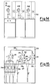
- Figure 14 is a front view of a further electrical panel comprising three switches according to the present invention;
- Figure 15 is a front view of the interior of the electrical panel of Figure 14 showing the three switches, one of which is provided with fuses;
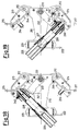
- Figure 16 is an enlarged sectional detail of the switch of Figure 15 shown in the isolated position;
- Figure 17 is a sectional detail on the line XVII-XVII of Figure 16;
- Figure 18 is a sectional view similar to that of Figure 16 showing the switch according to the invention in the closed position;
- Figure 19 is a sectional view similar to that of Figure 16 showing the switch according to the invention in the earthing position; and
- Figure 20 is a partly sectional side view of the set of three poles of the switch of Figure 15.
- With reference to Figures 1-7, a medium voltage operating-isolating switch with three positions insulated in sulphur hexafluoride according to the present invention comprises essentially a set of three insulating base support elements or
insulators 11 for a set of three poles mounted on asupport beam 12. An upper fixedcontact 14 with an associatedtulip element 16 comprising amale arcing contact 17 and contained in aninsulating nozzle 15 are fixed respectively onto eachsupport element 11, which extends upperly into a pumpingcylinder 13. The fixedcontact 14 is connected in known manner to arespective bus bar 18. - The
support element 11 also carries alower contact 19 connected to anearthing plate 21 via a throughinsulator 20. - A third
intermediate contact 22 is fixed to thesupport element 11 and is secured to aU-piece 23, inholes 24 of which there is pivoted a T-shaped arm 25 in the form of two spaced-apart facing plates, carrying at its free end a pair ofarcing contacts 26. Electrical contact between the U-piece 23 and thearm 25 is ensured bycup springs 45. This assembly forms a moving contact which is connected via a throughinsulator 43 to a current inlet or outlet. The pivoting is provided by ashaft 27 of insulating material which passes through each of the three poles, is supported on thesupport elements 11, and supports thecup springs 45 in addition to theU-pieces 23 and thearm 25. - The
arm 25 is also connected to and its position controlled by a secondinsulating shaft 28, which also passes through all three arms of the moving contacts to act as a pivot. Thearm 25 is rotated by twoinsulating rods 29 which emerge from a sealedmetal container 30 containing sulphur hexafluoride and frommetal seal bellows 31, and are controlled by a quick snap-engagement mechanism for the three positions, which is indicated overall by 32 and can be operated from the outside of the front of the switch by a rod, not shown. This device converts rotation into a linear movement determining the three operating positions, namely closed, isolated and earthed. - In addition two
insulating levers 33 are provided, each having a pair of throughholes 34 and 35 through which theshafts levers 33 are angular and at their free end they are connected by apin 36 to a pair ofsecond levers 37 which move apiston 38 connected to them by afurther pin 39. - A metal draining
blade 44 of equivalent shape has to be arranged between thesupport element 11 and thecylinder 13 to prevent any current circulation and passage between the isolated parts. - Such a structure provides a simple operating-isolating switch without fuses.
- If
fuses 46 are required to protect a transformer, not shown, abar 41 joining threecontacts 42 on the support elements is mounted in asuitable seat 40 in the lower part of thesupport element 11 at a sufficient distance from thelower contact 19 to ensure the necessary isolation required by the regulations for the relative class, and is earthed as in the case of thebeam 12. In this case thelower contact 19 is completely isolated by eliminating the throughinsulator 20 and the throughinsulator 43 and connecting the twocontacts fuse 46. The fuse outlet is again connected to a through insulator entirely similar to 43. - In a complementary manner each T-
shaped arm 25 has to carry asingle contact 47 for engagement with saidcontacts 42. - In this manner on rotating the
arm 25 into the earthing position, simultaneous earthing upstream and downstream of thefuse 46 is achieved by the connection between the movingcontacts contact 22, and the lowerfixed contacts - Both the switch provided with only the
fixed contacts 19 and movingcontacts 26 and the switch provided with said contacts and with furtherfixed contacts 42 and movingcontacts 47 are diagrammatically represented in the schematics of Figures 8 and 9 in the isolated position. These schematics again show that earthing can be achieved by a single arm carrying the moving contact, and that if a fuse is present earthing can be achieved both upstream and downstream of the fuse, again by a single arm carrying moving contacts. - With reference to Figures 1 to 3 it can also be seen that in an insulated electrical panel formed from three switches of the present invention, by providing a
single door 48 for each switch it is possible to see whether the individual switches are in the isolated position or not. It can also be seen that the upper front part of the panel comprises theseat 49 for inserting the operating lever (not shown) for association with each quick snap-action mechanism 32 which via the linear control represented by therod 29 switches between the three positions of the movingcontacts 26 and optionally 47 of the switch. - If the switch is provided with fuses (Figure 3), according to the present invention the
fuses 46 are positioned horizontally in anextractable drawer 50 aligned below the insulators coaxial with the three constituent poles of the switch. This positioning of the fuses allows them to be easily extracted and replaced frontally. - Figures 4 and 6 show how the switch of the present invention can be comfortably assembled in all its essential parts on a
rear beam 12 in the workshop. In this respect, when the switch has been assembled and completed on said beam, the beam has merely to be fixed to the interior of the panel structure and the relative conductors connected. This thus eliminates the need for arranging the contacts or special connectors for the insulated support elements in predetermined positions within the panel. - Figures 10-13 show a further medium voltage operating-isolating switch with three positions insulated in sulphur hexafluoride according to the present invention in which the set of three insulating
base support elements 11 is arranged transversely to the panel. In this embodiment, equal reference numerals indicate equal elements. Again in this case, the fixedcontact 14 is connected in known manner to a respective bus bar, not shown, and the throughinsulator 20 to an earthing plate, not shown. - The pivoting is achieved by a
shaft 27 of insulating material which is inserted through each of the three poles and is supported by the U-pieces 23 and thesupport elements 11. Thearms 25 of the three poles are fixed by pins to theshaft 27, coaxial to which there are also thesprings 45. - The
arms 25 are rotated by aflanged extension 128 thereto, which is connected to acomplementary flange 124 also extending into a shaft portion emerging from a sealed metal container, not shown, containing the sulphur hexafluoride. In an equivalent manner, on the front of the switch there is a quick snap-action mechanism, indicated overall by 32, for engaging the three positions. - Both the switch provided with only the fixed
contacts 19 and movingcontacts 26 and the switch provided with said contacts and with further fixedcontacts 42 and movingcontacts 47 are diagrammatically represented in the schematics of Figures 8 and 9 in the isolated position. - With reference to Figures 10-13 it can be seen that the upper front part of the panel comprises
inspection doors 48 andseats 49 for the insertion of the operating lever (not shown) to be associated with each quick snap-action mechanism 32 to switch between the three positions of the movingcontacts 26 and optionally 47 of the switch. - If the switch is provided with fuses (Figures 12 and 13), according to the present invention the
fuses 46 are positioned horizontally in anextractable drawer 50 aligned below the insulators and the three constituent poles of the switch. This positioning of the fuses also allows them to be easily extracted and replaced frontally. - With reference to Figures 14-20, a further compact three-position medium voltage operating-isolating switch insulated with fluid such as sulphur hexafluoride according to the present invention comprises essentially a set of three insulating base support elements or
insulators - Each support element is of specular box type and consists of two mutually
complementary parts holes 213 and relative projectingpins 214 on one and the other of theparts - This connection also fixes an upper
fixed contact 215 with an associatedmale arcing contact 216, and alower contact 217 with an associatedmale arcing contact 218. The fixedcontact 215 is connected in known manner to arespective bus bar 219, whereas thelower contact 217 is connected via a throughinsulator 220 to an earthingplate 221. - When formed, the
support element intermediate contact 222 which is fixed to thesupport element U-piece 223 closed lowerly and provided withpin extensions 224 on which there is pivoted a hollowcylindrical support 225 of insulating material for a telescopic arm connected to theintermediate contact 222. Thepin extensions 224 lie within thecylinder 225 and are maintained rigid with a first fixed expandable outercylindrical portion 227 of said telescopic arm. Electrical contact is ensured by cup springs 235 provided withinrecesses 236 formed in thepin extensions 224 and interacting between thesupport element cylindrical portion 228 is slidingly guided within said fixedportion 227 and carries at its free end, rigidly joined to its interior, atulip contact element 229 acting as a female arcing contact. The outer part of this free end of thesecond portion 228 is supported within anannular support element 230 which is pivoted at 226 within a first end of two half-arms 231 of insulating material. The other end of the two half-arms 231 is provided with a throughhole 232 and is pivoted to thesupport element central shaft 233, which is also the operating shaft. For engaging the three positions of the switch, a quick snap-action mechanism 237 is connected to theshaft 233 in a lateral position on one side. - The
annular support element 230 comprises afront hole 234 constituting the emission portion for the fluid, such as sulphur hexafluoride, which quenches the arc and is contained in the expandable chamber defined by the twoportions - This described telescopic arm assembly forms a moving contact which is connected via a through insulator 243 to a current inlet or outlet.
- Between that portion of the
support elements upper contact 215 and the remaining portion of the support elements, through holes, which are cut and open towards the outside to separate portions of the support elements, are provided to receive metal draining bars 244 of equivalent shape to the holes for preventing any current circulation and passage between the parts when isolated. - Such a structure forms a simple compact fuse-less operating-isolating switch of fluid type which by making the cylinder pumping element for the fluid, such as sulphur hexafluoride, rigid with and incorporated in the moving arm prevents deposition of any carbon-containing residues and hence avoids operational defects and discharges to earth.
- If
fuses 246 are required to protect a transformer, not shown,U-shaped contact elements 239 of bar form are mounted on the lower part of thesupport element holes 238. The sides of thecontact elements 239 are elastically yieldable and are mounted on thelower support tie 212, with their free ends facing aslot 240 formed centrally in two halves between the twosupport elements slot 240 there is inserted a free end of an open L-shapedcontact element 241 which is fixed in proximity to its other end to the body of the half-arms 231. The other end of thecontact element 241 abuts against acontact extension 242 which is inserted radially into the top of theannular support element 230 so that it makes contact with the free end of thesecond portion 228 of the telescopic arm. This structure ensures that with the switch in the contacts-closed position there is no interference between the contact elements and/or undesirable current passage, whereas when in the earthing position there is simultaneous earthing upstream and downstream of the fuse. - In this case the
lower contact 217 is completely isolated by eliminating the throughinsulator 220 and the through insulator 243 and connecting the twocontacts fuse 246. The fuse outlet is again connected to a through insulator entirely similar to 243. In all cases eachtelescopic arm contact extension 242 and acontact element 241 rigid with the half-arms 231 for engagement with saidbar contact elements 239. - In this manner on rotating the
telescopic arm fuse 246 is achieved by the connection between the movingcontacts fixed contacts - Both the switch provided with only the fixed and moving contacts and the switch provided with said contacts and with further fixed and moving contacts are diagrammatically represented in the schematics of Figure 14 on the front of an
electrical panel 250 in the isolated position. These schematics again show that earthing can be achieved by a single arm carrying the moving contact, and that if a fuse is present earthing can be achieved both upstream and downstream of the fuse again by a single arm carrying moving contacts. - With reference to Figure 14 it can also be seen that in an insulated electrical panel formed from three switches of the present invention, by providing a
single door 248 for each switch it is possible to see whether the individual switches are in the isolated position or not. In this respect, the shape of thesupport element - If the switch is provided with fuses (Figure 16), according to the present invention the
fuses 246 are positioned horizontally in anextractable drawer 250 aligned below the insulators coaxially with the three constituent poles of the switch. This positioning of the fuses also allows them to be easily extracted and replaced frontally. - The switch of the present invention can be assembled in all its essential parts on the two
rear ties 212 in the workshop. In this respect, when the switch has been assembled and completed on said ties, it has merely to be fixed on the interior of the panel structure and the relative conductors connected. This thus eliminates the need for arranging the contacts or special connectors for the insulated support elements in predetermined positions within the panel. - In all the switches of the present invention, advantageously each insulated support element and each rotary arm is suitable for use in a switch without or with fuses, so that the additional moving and fixed contacts can then be quickly fitted to them.
Claims (20)
- A medium voltage operating-isolating switch with three positions insulated in sulphur hexafluoride comprising a set of three poles, each pole comprising a fixed contact and a mobile contact, said fixed contact carrying, within an insulating nozzle, an associated tulip element containing a male arcing contact and being connected to a respective bus bar, said mobile contact being arranged on a pivoted arm rotatable between a first closed position in engagement with said fixed contact, a second isolated position and a third earthed position, characterised in that said mobile and fixed contacts of said set of three poles are arranged on three insulating base support elements fixed to a single support beam, a relative cylinder which pumps said sulphur hexafluoride into said insulating nozzle being associated via an insulated lever with each of said arms carrying said mobile contacts, a metal draining element being provided between each of said insulating support elements and said pumping cylinders.
- A switch as claimed in claim 1, characterised in that said three arms carrying said mobile contacts comprise two spaced-apart through holes through which a pair of shafts of insulating material are inserted, one of these latter having pivoted to it an insulating rod which emerges from an insulated container containing said sulphur hexafluoride to be connected to a quick snap-action mechanism for engaging said three positions, the other of said pair of shafts carrying a set of three levers for operating the pistons of said cylinders.
- A switch as claimed in claim 1, characterised in that further contacts can be fitted to said insulating support elements and said arms for earthing fuses associated with said switch.
- A switch as claimed in claim 1, characterised in that each of said arms consists of two plates pivoted to a relative support element via a U-piece, contact between said two plates of said arms and said U-piece being achieved by springs arranged coaxially on said pivoting shaft.
- An insulated panel comprising at least one switch in accordance with the preceding claims, characterised by comprising a frontal door for observing the three positions of the constituent elements of the three poles.
- An insulated panel as claimed in claim 5, characterised by comprising a frontwardly extractable horizontal drawer positioned below said switch and containing three fuses axially aligned with and below said three poles.
- An insulated panel as claimed in claim 5, characterised by comprising in an upper front position a seat for inserting an operating lever for said quick snap-action mechanism.
- A medium voltage operating-isolating switch with three positions insulated in sulphur hexafluoride comprising a set of three poles, each pole comprising a fixed contact and a mobile contact, said fixed contact carrying, within an insulating nozzle, an associated tulip element containing a male arcing contact and being connected to a respective bus bar, said mobile contact being arranged on a pivoted arm rotatable between a first closed position in engagement with said fixed contact, a second isolated position and a third earthed position, characterised in that said mobile and fixed contacts of said set of three poles are arranged on three insulating base support elements fixed to a single support beam, a relative cylinder which pumps said sulphur hexafluoride into said insulating nozzle being associated via an insulated lever with each of said arms carrying said mobile contacts, a metal draining element being provided between each of said insulating support elements and said pumping cylinders.
- A switch as claimed in claim 8, characterised in that said three arms carrying said mobile contacts are of curved shape, and are fixed spaced-apart onto a through shaft of insulating material which is pivoted within each of said three support elements and emerges from an insulated container containing said sulphur hexafluoride to be connected to a quick snap-action mechanism for engaging said three positions and arranged transversely to said three poles, there being connected to said shaft a set of three levers for operating the pistons of said cylinders.
- A switch as claimed in claim 8, characterised in that further contacts can be fitted to said insulating support elements and said arms for earthing fuses associated with said switch.
- A switch as claimed in claim 8, characterised in that each of said arms consists of two plates fixed to said shaft and pivoted to a relative support element via a U-piece, contact between said two plates of said arms and said U-piece being achieved by springs arranged coaxially on said pivoting shaft.
- An insulated panel comprising at least one switch in accordance with claims 8-11, characterised by comprising a frontwardly extractable horizontal drawer positioned below said switch and containing a set of three fuses arranged parallel to the axis of said three poles.
- An insulated panel as claimed in claim 12, characterised by comprising in an upper front position a seat for inserting an operating lever for said quick snap-action mechanism.
- A compact fluid-insulated three-position medium voltage operating-isolating switch comprising a set of three poles, each pole comprising a fixed contact and a mobile contact, the fixed contact carrying an associated male arcing contact and the mobile contact being arranged on a pivoted arm rotatable between a first closed position in engagement with said fixed contact, a second isolated position and a third earthed position, characterised in that said mobile and fixed contacts of said set of three poles are arranged on three insulating base support elements fixed to support ties, each of said arms carrying said mobile contacts being of telescopic type and having said mobile contacts associated with it via an insulated lever connected to an operating rod, within said rotatable arm there being provided a cylinder for pumping the fluid onto said fixed contact, at least one metal draining element being provided on each of said insulating support elements between the portion carrying said fixed contact and the remaining portion of said support elements.
- A switch as claimed in claim 14, characterised in that said insulating support elements are of box type in the form of two complementary parts which can be fixed together by mutual fixing means.
- A switch as claimed in claim 14, characterised in that each of said arms consists of a support pivoted to a relative support element by way of a U-piece, said support carrying two mutually expandable cylindrical portions, at least one of the two supporting a tulip contact element, contact between said U-piece and said expandable cylindrical portions being achieved by springs arranged coaxial to a pivot by which said support is pivoted to said U-piece.
- A switch as claimed in claim 16, characterised in that a free end of said pivoted support is supported in an annular support element pivoted to the ends of half-arms of insulating material which can be caused to rotate into the three positions by an operating shaft passingly fixed to the other end of said half-arms and connected to a quick snap-action mechanism.
- A switch as claimed in claim 14, characterised in that further contacts can be fitted to said insulating support elements and said telescopic arms in complementary positions for earthing fuses associated with said switch.
- A switch as claimed in claim 18, characterised in that said further contacts for earthing the fuses are respectively a contact element supported on half-arms pivoted to insulating elements of said telescopic arms, a contact extension which extends from said mobile contacts and bar contact elements fixed to said support elements, said contact element, said contact extension and said bar contact elements being electrically connected together only when in the third earthed position.
- An insulated panel comprising at least one switch in accordance with claims 14-19, characterised by comprising a frontwardly extractable horizontal drawer positioned below said switch and containing a set of three fuses associated with said three poles.
Applications Claiming Priority (6)
| Application Number | Priority Date | Filing Date | Title |
|---|---|---|---|
| ITMI911435 | 1991-05-24 | ||
| ITMI911436 | 1991-05-24 | ||
| ITMI911435A IT1260588B (en) | 1991-05-24 | 1991-05-24 | Sulphur-hexafluoride-insulated three-position medium voltage operating/switching equipment |
| ITMI911436A IT1252615B (en) | 1991-05-24 | 1991-05-24 | Sulphur-hexafluoride-insulated three-position medium voltage operating/switching equipment |
| ITMI911652 | 1991-06-17 | ||
| ITMI911652A IT1248067B (en) | 1991-06-17 | 1991-06-17 | Three position medium voltage fluid insulated compact operating and cut-off apparatus |
Publications (3)
| Publication Number | Publication Date |
|---|---|
| EP0517295A2 true EP0517295A2 (en) | 1992-12-09 |
| EP0517295A3 EP0517295A3 (en) | 1993-03-10 |
| EP0517295B1 EP0517295B1 (en) | 1997-12-17 |
Family
ID=27273943
Family Applications (1)
| Application Number | Title | Priority Date | Filing Date |
|---|---|---|---|
| EP92201448A Expired - Lifetime EP0517295B1 (en) | 1991-05-24 | 1992-05-21 | Medium voltage switch with three positions insulated in sulphur hexafluoride |
Country Status (4)
| Country | Link |
|---|---|
| EP (1) | EP0517295B1 (en) |
| AT (1) | ATE161356T1 (en) |
| DE (1) | DE69223549T2 (en) |
| ES (1) | ES2113401T3 (en) |
Cited By (9)
| Publication number | Priority date | Publication date | Assignee | Title |
|---|---|---|---|---|
| WO2008015032A1 (en) * | 2006-07-31 | 2008-02-07 | Siemens Aktiengesellschaft | Closure cover for a safety enclosure for an electrical switchgear assembly |
| WO2008014875A1 (en) | 2006-07-31 | 2008-02-07 | Siemens Aktiengesellschaft | Connecting piece for fitting to a protection housing |
| EP2312603A1 (en) * | 2009-10-15 | 2011-04-20 | ABB Technology AG | Rotary switch-disconnector |
| CN102157296A (en) * | 2011-03-18 | 2011-08-17 | 湖州电力局 | High-voltage dual-power supply changing-over combination switch |
| FR3094836A1 (en) * | 2019-04-02 | 2020-10-09 | Pommier | Arc breaking device |
| EP4057314A1 (en) * | 2021-03-11 | 2022-09-14 | ABB Schweiz AG | Switch-fuse module |
| EP4057315A1 (en) * | 2021-03-11 | 2022-09-14 | ABB Schweiz AG | Switch-fuse module |
| CN119270006A (en) * | 2024-12-05 | 2025-01-07 | 江苏恒高电气制造有限公司 | A phase-changing withstand voltage test device for three-phase common-compartment products |
| US12444559B2 (en) | 2022-05-12 | 2025-10-14 | Abb Schweiz Ag | Medium voltage switching apparatus |
Family Cites Families (8)
| Publication number | Priority date | Publication date | Assignee | Title |
|---|---|---|---|---|
| BE473294A (en) * | 1946-05-21 | |||
| DE976331C (en) * | 1954-09-03 | 1963-07-04 | Frobert Michaelis Dipl Ing | Compressed air switch with self-generated blowing air |
| CH337905A (en) * | 1955-12-16 | 1959-04-30 | Bbc Brown Boveri & Cie | Multipole switch with partitions |
| FR1367073A (en) * | 1963-07-10 | 1964-07-17 | Cem Comp Electro Mec | Switch-disconnector for preferably prefabricated electrical installations |
| DE8115913U1 (en) * | 1981-05-29 | 1981-08-06 | Fritz Driescher Spezialfabrik für Elektrizitätswerksbedarf, 5144 Wegberg | Gas-insulated metal-enclosed control panel |
| DE3215234C2 (en) * | 1982-04-23 | 1986-10-30 | Felten & Guilleaume Energietechnik GmbH, 5000 Köln | Encapsulated medium-voltage switchgear filled with insulating gas |
| DE3513499A1 (en) * | 1985-04-16 | 1986-10-16 | Brown, Boveri & Cie Ag, 6800 Mannheim | SWITCH DISCONNECTOR AND SWITCHGEAR WITH THIS SWITCH DISCONNECTOR |
| FR2655768B1 (en) * | 1989-12-13 | 1993-10-08 | Merlin Gerin | HIGH VOLTAGE TRIPOLAR GAS INSULATED SWITCH. |
-
1992
- 1992-05-21 ES ES92201448T patent/ES2113401T3/en not_active Expired - Lifetime
- 1992-05-21 DE DE69223549T patent/DE69223549T2/en not_active Expired - Fee Related
- 1992-05-21 AT AT92201448T patent/ATE161356T1/en not_active IP Right Cessation
- 1992-05-21 EP EP92201448A patent/EP0517295B1/en not_active Expired - Lifetime
Cited By (18)
| Publication number | Priority date | Publication date | Assignee | Title |
|---|---|---|---|---|
| CN101496119B (en) * | 2006-07-31 | 2012-12-12 | 西门子公司 | Connecting piece for fitting to a protection housing |
| WO2008014875A1 (en) | 2006-07-31 | 2008-02-07 | Siemens Aktiengesellschaft | Connecting piece for fitting to a protection housing |
| WO2008015032A1 (en) * | 2006-07-31 | 2008-02-07 | Siemens Aktiengesellschaft | Closure cover for a safety enclosure for an electrical switchgear assembly |
| RU2427054C2 (en) * | 2006-07-31 | 2011-08-20 | Сименс Акциенгезелльшафт | Closing cover for housing with fuses of electric distribution device |
| RU2430442C2 (en) * | 2006-07-31 | 2011-09-27 | Сименс Акциенгезелльшафт | Connector to be mounted on casing with fuses |
| CN101496125B (en) * | 2006-07-31 | 2012-03-14 | 西门子公司 | Connecting piece for fitting to a protection housing |
| EP2312603A1 (en) * | 2009-10-15 | 2011-04-20 | ABB Technology AG | Rotary switch-disconnector |
| WO2011044983A1 (en) * | 2009-10-15 | 2011-04-21 | Abb Technology Ag | Rotary switch- disconnector |
| CN102157296A (en) * | 2011-03-18 | 2011-08-17 | 湖州电力局 | High-voltage dual-power supply changing-over combination switch |
| CN102157296B (en) * | 2011-03-18 | 2013-06-12 | 湖州电力局 | High-voltage dual-power supply changing-over combination switch |
| FR3094836A1 (en) * | 2019-04-02 | 2020-10-09 | Pommier | Arc breaking device |
| EP3719824A3 (en) * | 2019-04-02 | 2020-11-11 | Pommier | Device for arc-cutting |
| EP4057314A1 (en) * | 2021-03-11 | 2022-09-14 | ABB Schweiz AG | Switch-fuse module |
| EP4057315A1 (en) * | 2021-03-11 | 2022-09-14 | ABB Schweiz AG | Switch-fuse module |
| US11749976B2 (en) | 2021-03-11 | 2023-09-05 | Abb Schweiz Ag | Switch-fuse module |
| US11784015B2 (en) | 2021-03-11 | 2023-10-10 | Abb Schweiz Ag | Switch-fuse module |
| US12444559B2 (en) | 2022-05-12 | 2025-10-14 | Abb Schweiz Ag | Medium voltage switching apparatus |
| CN119270006A (en) * | 2024-12-05 | 2025-01-07 | 江苏恒高电气制造有限公司 | A phase-changing withstand voltage test device for three-phase common-compartment products |
Also Published As
| Publication number | Publication date |
|---|---|
| DE69223549T2 (en) | 1998-07-23 |
| ES2113401T3 (en) | 1998-05-01 |
| EP0517295A3 (en) | 1993-03-10 |
| DE69223549D1 (en) | 1998-01-29 |
| ATE161356T1 (en) | 1998-01-15 |
| EP0517295B1 (en) | 1997-12-17 |
Similar Documents
| Publication | Publication Date | Title |
|---|---|---|
| US5796060A (en) | Gas insulated switchgear with grounding and disconnecting switches | |
| JP4709756B2 (en) | Ground switch with 3 switch positions | |
| US4379957A (en) | Modular "Y"-type enclosure elements for gas insulated substations | |
| US8350169B2 (en) | Three-positions disconnector for medium voltage panels | |
| US20010025828A1 (en) | Three-position electrical switch having a switching element that is movable in axial translation | |
| EP2565897B1 (en) | Switchgear and switchgear operating method | |
| PT87407B (en) | HIGH POLYMERIC TENSER DISTRIBUTOR ARMORED WITH GAS FILLING UNDER PRESSURE | |
| US20130048478A1 (en) | Switch arrangement for an electrical switchgear | |
| EP0517295B1 (en) | Medium voltage switch with three positions insulated in sulphur hexafluoride | |
| EP1826791A2 (en) | Three-position vacuum interrupter disconnect switch providing current interruption, disconnection and grounding | |
| KR0136383B1 (en) | Gas Insulated Switchgear | |
| EP0145994B1 (en) | Medium voltage switching device | |
| EP3336870B1 (en) | A gis with a disconnector-earthing switch | |
| CN87102299A (en) | Metal armored switchgear with division into closed compartments | |
| US20070119818A1 (en) | Compressed-gas-insulated switch-disconnector module and bushing configuration | |
| CS250246B2 (en) | Metal-enclosed gas-insulated distribution system | |
| US3397293A (en) | Metal-clad switchgear employing vacuum type circuit interrupters | |
| KR100738725B1 (en) | Electrical switch with compartmentd metal case to accept disconnectors | |
| EP1629581B1 (en) | Disconnecting switch assembly | |
| US3691332A (en) | Vacuum-type electric switchgear | |
| CN115085078A (en) | Switch fuse module | |
| US7485807B2 (en) | Gas-insulated bus bar component comprising outdoor bushings | |
| US20080042786A1 (en) | Power Switch Comprising an Interrupter Unit Disposed within an Encapsulating Housing | |
| EP0008513A1 (en) | Switch arrangement for three-phase electrical supply | |
| EP0917721B1 (en) | Sf6 gas-insulated switch installation for electricity distribution supply networks |
Legal Events
| Date | Code | Title | Description |
|---|---|---|---|
| PUAI | Public reference made under article 153(3) epc to a published international application that has entered the european phase |
Free format text: ORIGINAL CODE: 0009012 |
|
| AK | Designated contracting states |
Kind code of ref document: A2 Designated state(s): AT BE CH DE DK ES FR GB GR IT LI LU NL PT SE |
|
| PUAL | Search report despatched |
Free format text: ORIGINAL CODE: 0009013 |
|
| AK | Designated contracting states |
Kind code of ref document: A3 Designated state(s): AT BE CH DE DK ES FR GB GR IT LI LU NL PT SE |
|
| 17P | Request for examination filed |
Effective date: 19930903 |
|
| 17Q | First examination report despatched |
Effective date: 19950411 |
|
| GRAG | Despatch of communication of intention to grant |
Free format text: ORIGINAL CODE: EPIDOS AGRA |
|
| GRAG | Despatch of communication of intention to grant |
Free format text: ORIGINAL CODE: EPIDOS AGRA |
|
| GRAH | Despatch of communication of intention to grant a patent |
Free format text: ORIGINAL CODE: EPIDOS IGRA |
|
| GRAH | Despatch of communication of intention to grant a patent |
Free format text: ORIGINAL CODE: EPIDOS IGRA |
|
| GRAA | (expected) grant |
Free format text: ORIGINAL CODE: 0009210 |
|
| AK | Designated contracting states |
Kind code of ref document: B1 Designated state(s): AT BE CH DE DK ES FR GB GR IT LI LU NL PT SE |
|
| PG25 | Lapsed in a contracting state [announced via postgrant information from national office to epo] |
Ref country code: GR Free format text: LAPSE BECAUSE OF FAILURE TO SUBMIT A TRANSLATION OF THE DESCRIPTION OR TO PAY THE FEE WITHIN THE PRESCRIBED TIME-LIMIT Effective date: 19971217 Ref country code: DK Free format text: LAPSE BECAUSE OF NON-PAYMENT OF DUE FEES Effective date: 19971217 Ref country code: CH Free format text: LAPSE BECAUSE OF FAILURE TO SUBMIT A TRANSLATION OF THE DESCRIPTION OR TO PAY THE FEE WITHIN THE PRESCRIBED TIME-LIMIT Effective date: 19971217 Ref country code: AT Free format text: LAPSE BECAUSE OF FAILURE TO SUBMIT A TRANSLATION OF THE DESCRIPTION OR TO PAY THE FEE WITHIN THE PRESCRIBED TIME-LIMIT Effective date: 19971217 Ref country code: NL Free format text: LAPSE BECAUSE OF FAILURE TO SUBMIT A TRANSLATION OF THE DESCRIPTION OR TO PAY THE FEE WITHIN THE PRESCRIBED TIME-LIMIT Effective date: 19971217 Ref country code: LI Free format text: LAPSE BECAUSE OF FAILURE TO SUBMIT A TRANSLATION OF THE DESCRIPTION OR TO PAY THE FEE WITHIN THE PRESCRIBED TIME-LIMIT Effective date: 19971217 |
|
| REF | Corresponds to: |
Ref document number: 161356 Country of ref document: AT Date of ref document: 19980115 Kind code of ref document: T |
|
| REG | Reference to a national code |
Ref country code: CH Ref legal event code: EP |
|
| REF | Corresponds to: |
Ref document number: 69223549 Country of ref document: DE Date of ref document: 19980129 |
|
| ITF | It: translation for a ep patent filed | ||
| PG25 | Lapsed in a contracting state [announced via postgrant information from national office to epo] |
Ref country code: SE Free format text: LAPSE BECAUSE OF FAILURE TO SUBMIT A TRANSLATION OF THE DESCRIPTION OR TO PAY THE FEE WITHIN THE PRESCRIBED TIME-LIMIT Effective date: 19980317 |
|
| ET | Fr: translation filed | ||
| REG | Reference to a national code |
Ref country code: ES Ref legal event code: FG2A Ref document number: 2113401 Country of ref document: ES Kind code of ref document: T3 |
|
| PG25 | Lapsed in a contracting state [announced via postgrant information from national office to epo] |
Ref country code: GB Free format text: LAPSE BECAUSE OF NON-PAYMENT OF DUE FEES Effective date: 19980521 Ref country code: LU Free format text: LAPSE BECAUSE OF NON-PAYMENT OF DUE FEES Effective date: 19980521 |
|
| NLV1 | Nl: lapsed or annulled due to failure to fulfill the requirements of art. 29p and 29m of the patents act | ||
| REG | Reference to a national code |
Ref country code: PT Ref legal event code: SC4A Free format text: AVAILABILITY OF NATIONAL TRANSLATION Effective date: 19980312 Ref country code: CH Ref legal event code: PL |
|
| PLBE | No opposition filed within time limit |
Free format text: ORIGINAL CODE: 0009261 |
|
| STAA | Information on the status of an ep patent application or granted ep patent |
Free format text: STATUS: NO OPPOSITION FILED WITHIN TIME LIMIT |
|
| 26N | No opposition filed | ||
| GBPC | Gb: european patent ceased through non-payment of renewal fee |
Effective date: 19980521 |
|
| PGFP | Annual fee paid to national office [announced via postgrant information from national office to epo] |
Ref country code: PT Payment date: 20010503 Year of fee payment: 10 |
|
| PGFP | Annual fee paid to national office [announced via postgrant information from national office to epo] |
Ref country code: DE Payment date: 20010514 Year of fee payment: 10 |
|
| PGFP | Annual fee paid to national office [announced via postgrant information from national office to epo] |
Ref country code: FR Payment date: 20010518 Year of fee payment: 10 |
|
| PGFP | Annual fee paid to national office [announced via postgrant information from national office to epo] |
Ref country code: ES Payment date: 20010530 Year of fee payment: 10 |
|
| PGFP | Annual fee paid to national office [announced via postgrant information from national office to epo] |
Ref country code: BE Payment date: 20010717 Year of fee payment: 10 |
|
| PG25 | Lapsed in a contracting state [announced via postgrant information from national office to epo] |
Ref country code: ES Free format text: LAPSE BECAUSE OF NON-PAYMENT OF DUE FEES Effective date: 20020522 |
|
| PG25 | Lapsed in a contracting state [announced via postgrant information from national office to epo] |
Ref country code: BE Free format text: LAPSE BECAUSE OF NON-PAYMENT OF DUE FEES Effective date: 20020531 |
|
| PG25 | Lapsed in a contracting state [announced via postgrant information from national office to epo] |
Ref country code: PT Free format text: LAPSE BECAUSE OF NON-PAYMENT OF DUE FEES Effective date: 20021130 |
|
| PG25 | Lapsed in a contracting state [announced via postgrant information from national office to epo] |
Ref country code: DE Free format text: LAPSE BECAUSE OF NON-PAYMENT OF DUE FEES Effective date: 20021203 |
|
| PG25 | Lapsed in a contracting state [announced via postgrant information from national office to epo] |
Ref country code: FR Free format text: LAPSE BECAUSE OF NON-PAYMENT OF DUE FEES Effective date: 20030131 |
|
| REG | Reference to a national code |
Ref country code: PT Ref legal event code: MM4A Free format text: LAPSE DUE TO NON-PAYMENT OF FEES Effective date: 20021130 Ref country code: FR Ref legal event code: ST |
|
| REG | Reference to a national code |
Ref country code: ES Ref legal event code: FD2A Effective date: 20030611 |
|
| PGFP | Annual fee paid to national office [announced via postgrant information from national office to epo] |
Ref country code: IT Payment date: 20110525 Year of fee payment: 20 |