EP0516621B1 - Dynamic codebook for efficient speech coding based on algebraic codes - Google Patents
Dynamic codebook for efficient speech coding based on algebraic codes Download PDFInfo
- Publication number
- EP0516621B1 EP0516621B1 EP90915956A EP90915956A EP0516621B1 EP 0516621 B1 EP0516621 B1 EP 0516621B1 EP 90915956 A EP90915956 A EP 90915956A EP 90915956 A EP90915956 A EP 90915956A EP 0516621 B1 EP0516621 B1 EP 0516621B1
- Authority
- EP
- European Patent Office
- Prior art keywords
- codeword
- signal
- algebraic
- sound signal
- calculating
- Prior art date
- Legal status (The legal status is an assumption and is not a legal conclusion. Google has not performed a legal analysis and makes no representation as to the accuracy of the status listed.)
- Expired - Lifetime
Links
- 238000000034 method Methods 0.000 claims abstract description 65
- 230000005284 excitation Effects 0.000 claims abstract description 39
- 230000005236 sound signal Effects 0.000 claims description 68
- 238000012546 transfer Methods 0.000 claims description 41
- 238000001914 filtration Methods 0.000 claims description 25
- 230000003595 spectral effect Effects 0.000 claims description 20
- 230000004044 response Effects 0.000 claims description 16
- 230000015572 biosynthetic process Effects 0.000 claims description 15
- 230000007774 longterm Effects 0.000 claims description 15
- 238000003786 synthesis reaction Methods 0.000 claims description 15
- 238000004040 coloring Methods 0.000 claims description 11
- 238000012545 processing Methods 0.000 claims description 11
- 239000000203 mixture Substances 0.000 claims description 10
- 239000011159 matrix material Substances 0.000 claims description 9
- 230000002194 synthesizing effect Effects 0.000 claims description 9
- 230000002087 whitening effect Effects 0.000 claims description 9
- 230000006870 function Effects 0.000 description 21
- 238000010586 diagram Methods 0.000 description 3
- 238000013459 approach Methods 0.000 description 2
- 238000010420 art technique Methods 0.000 description 2
- 238000009472 formulation Methods 0.000 description 2
- 230000004048 modification Effects 0.000 description 2
- 238000012986 modification Methods 0.000 description 2
- 238000000059 patterning Methods 0.000 description 2
- 230000009467 reduction Effects 0.000 description 2
- 230000000717 retained effect Effects 0.000 description 2
- 238000001228 spectrum Methods 0.000 description 2
- 239000013598 vector Substances 0.000 description 2
- 238000004458 analytical method Methods 0.000 description 1
- 230000005540 biological transmission Effects 0.000 description 1
- 238000012512 characterization method Methods 0.000 description 1
- 239000003086 colorant Substances 0.000 description 1
- 239000002131 composite material Substances 0.000 description 1
- 238000009795 derivation Methods 0.000 description 1
- 238000013461 design Methods 0.000 description 1
- 230000002708 enhancing effect Effects 0.000 description 1
- 230000006872 improvement Effects 0.000 description 1
- 238000010845 search algorithm Methods 0.000 description 1
- 238000007493 shaping process Methods 0.000 description 1
Images


Classifications
-
- G—PHYSICS
- G10—MUSICAL INSTRUMENTS; ACOUSTICS
- G10L—SPEECH ANALYSIS TECHNIQUES OR SPEECH SYNTHESIS; SPEECH RECOGNITION; SPEECH OR VOICE PROCESSING TECHNIQUES; SPEECH OR AUDIO CODING OR DECODING
- G10L19/00—Speech or audio signals analysis-synthesis techniques for redundancy reduction, e.g. in vocoders; Coding or decoding of speech or audio signals, using source filter models or psychoacoustic analysis
- G10L19/04—Speech or audio signals analysis-synthesis techniques for redundancy reduction, e.g. in vocoders; Coding or decoding of speech or audio signals, using source filter models or psychoacoustic analysis using predictive techniques
- G10L19/08—Determination or coding of the excitation function; Determination or coding of the long-term prediction parameters
- G10L19/10—Determination or coding of the excitation function; Determination or coding of the long-term prediction parameters the excitation function being a multipulse excitation
-
- G—PHYSICS
- G10—MUSICAL INSTRUMENTS; ACOUSTICS
- G10L—SPEECH ANALYSIS TECHNIQUES OR SPEECH SYNTHESIS; SPEECH RECOGNITION; SPEECH OR VOICE PROCESSING TECHNIQUES; SPEECH OR AUDIO CODING OR DECODING
- G10L19/00—Speech or audio signals analysis-synthesis techniques for redundancy reduction, e.g. in vocoders; Coding or decoding of speech or audio signals, using source filter models or psychoacoustic analysis
- G10L19/04—Speech or audio signals analysis-synthesis techniques for redundancy reduction, e.g. in vocoders; Coding or decoding of speech or audio signals, using source filter models or psychoacoustic analysis using predictive techniques
- G10L19/08—Determination or coding of the excitation function; Determination or coding of the long-term prediction parameters
- G10L19/12—Determination or coding of the excitation function; Determination or coding of the long-term prediction parameters the excitation function being a code excitation, e.g. in code excited linear prediction [CELP] vocoders
-
- G—PHYSICS
- G10—MUSICAL INSTRUMENTS; ACOUSTICS
- G10L—SPEECH ANALYSIS TECHNIQUES OR SPEECH SYNTHESIS; SPEECH RECOGNITION; SPEECH OR VOICE PROCESSING TECHNIQUES; SPEECH OR AUDIO CODING OR DECODING
- G10L19/00—Speech or audio signals analysis-synthesis techniques for redundancy reduction, e.g. in vocoders; Coding or decoding of speech or audio signals, using source filter models or psychoacoustic analysis
-
- G—PHYSICS
- G10—MUSICAL INSTRUMENTS; ACOUSTICS
- G10L—SPEECH ANALYSIS TECHNIQUES OR SPEECH SYNTHESIS; SPEECH RECOGNITION; SPEECH OR VOICE PROCESSING TECHNIQUES; SPEECH OR AUDIO CODING OR DECODING
- G10L19/00—Speech or audio signals analysis-synthesis techniques for redundancy reduction, e.g. in vocoders; Coding or decoding of speech or audio signals, using source filter models or psychoacoustic analysis
- G10L2019/0001—Codebooks
- G10L2019/0004—Design or structure of the codebook
-
- G—PHYSICS
- G10—MUSICAL INSTRUMENTS; ACOUSTICS
- G10L—SPEECH ANALYSIS TECHNIQUES OR SPEECH SYNTHESIS; SPEECH RECOGNITION; SPEECH OR VOICE PROCESSING TECHNIQUES; SPEECH OR AUDIO CODING OR DECODING
- G10L19/00—Speech or audio signals analysis-synthesis techniques for redundancy reduction, e.g. in vocoders; Coding or decoding of speech or audio signals, using source filter models or psychoacoustic analysis
- G10L2019/0001—Codebooks
- G10L2019/0007—Codebook element generation
- G10L2019/0008—Algebraic codebooks
-
- G—PHYSICS
- G10—MUSICAL INSTRUMENTS; ACOUSTICS
- G10L—SPEECH ANALYSIS TECHNIQUES OR SPEECH SYNTHESIS; SPEECH RECOGNITION; SPEECH OR VOICE PROCESSING TECHNIQUES; SPEECH OR AUDIO CODING OR DECODING
- G10L19/00—Speech or audio signals analysis-synthesis techniques for redundancy reduction, e.g. in vocoders; Coding or decoding of speech or audio signals, using source filter models or psychoacoustic analysis
- G10L2019/0001—Codebooks
- G10L2019/0011—Long term prediction filters, i.e. pitch estimation
-
- G—PHYSICS
- G10—MUSICAL INSTRUMENTS; ACOUSTICS
- G10L—SPEECH ANALYSIS TECHNIQUES OR SPEECH SYNTHESIS; SPEECH RECOGNITION; SPEECH OR VOICE PROCESSING TECHNIQUES; SPEECH OR AUDIO CODING OR DECODING
- G10L25/00—Speech or voice analysis techniques not restricted to a single one of groups G10L15/00 - G10L21/00
- G10L25/03—Speech or voice analysis techniques not restricted to a single one of groups G10L15/00 - G10L21/00 characterised by the type of extracted parameters
- G10L25/06—Speech or voice analysis techniques not restricted to a single one of groups G10L15/00 - G10L21/00 characterised by the type of extracted parameters the extracted parameters being correlation coefficients
Definitions
- the present invention relates to a new technique for digitally encoding and decoding in particular but not exclusively speech signals in view of transmitting and synthesizing these speech signals.
- Efficient digital speech encoding techniques with good subjective quality/bit rate tradeoffs are increasingly in demand for numerous applications such as voice transmission over satellites, land mobile, digital radio or packed network, for voice storage, voice response and secure telephony.
- CELP Code Excited Linear Prediction
- the speech signal is sampled and converted into successive blocks of a predetermined number of samples.
- Each block of samples is synthesized by filtering an appropriate innovation sequence from a codebook, scaled by a gain factor, through two filters having transfer functions varying in time.
- the first filter is a Long Term Predictor filter (LTP) modeling the pseudoperiodicity of speech, in particular due to pitch, while the second one is a Short Term Predictor filter (STP) modeling the spectral characteristics of the speech signal.
- LTP Long Term Predictor filter
- STP Short Term Predictor filter
- the encoding procedure used to determine the parameters necessary to perform this synthesis is an analysis by synthesis technique.
- the synthetic output is computed for all candidate innovation sequences from the codebook.
- the retained codeword is the one corresponding to the synthetic output which is closer to the original speech signal according to a perceptually weighted distortion measure.
- the first proposed structured codebooks are called stochastic codebooks. They consist of an actual set of stored sequences of N random samples. More efficient stochastic codebooks propose derivation of a codeword by removing one or more elements from the beginning of the previous codeword and adding one or more new elements at the end thereof. More recently, stochastic codebooks based on linear combinations of a small set of stored basis vectors have greatly reduced the search complexity. Finally, some algebraic structures have also been proposed as excitation codebooks with efficient search procedures. However, the latter are designed for speed and they lack flexibility in constructing codebooks with good subjective quality characteristics.
- the main object of the present invention is to combine an algebraic codebook and a filter with a transfer function varying in time, to produce a dynamic codebook offering both the speed and memory saving advantages of the above discussed structured codebooks while reducing the computation complexity of the Code Excited Linear Prediction (CELP) technique and enhancing the subjective quality of speech.
- CELP Code Excited Linear Prediction
- a method of producing an excitation signal to be used by a sound signal synthesis means to synthesize a sound signal comprising the step of generating a codeword signal in response to an index signal associated to the codeword signal, this signal generating step using an algebraic code to generate the codeword signal.
- the method is characterized in that it further comprises the step of filtering the generated codeword signal to produce the excitation signal, this filtering step comprising processing the codeword signal through a coloring filter having a transfer function varying in time in relation to parameters representative of spectral characteristics of the sound signal to thereby shape frequency characteristics of the excitation signal so as to damp frequencies perceptually annoying a human ear.
- the signal generating step comprises using a sparse algebraic code to generate the codeword signal
- the filtering step comprises varying the transfer function of the coloring filter in relation to linear predictive coding parameters representative of spectral characteristics of the sound signal.
- a dynamic codebook for producing an excitation signal to be used by a sound signal synthesis means to synthesize a sound signal comprising means for generating a codeword signal in response to an index signal associated to the codeword signal, these means for generating a codeword signal using an algebraic code to generate the codeword signal.
- the dynamic codebook is characterized in that it further comprises means for filtering the generated codeword signal to produce the excitation signal, these filtering means comprising a coloring filter having a transfer function varying in time in relation to parameters representative of spectral characteristics of the sound signal to thereby shape frequency characteristics of the excitation signal so as to damp frequencies perceptually annoying a human ear.
- the means for generating a codeword signal comprises means responsive to a sparse algebraic code to generate the codeword signal, and the coloring filter has a transfer function varying in time in relation to linear predictive coding parameters representative of spectral characteristics of the sound signal.
- the present invention also relates to a method of encoding a sound signal in view of subsequently synthesizing the sound signal through a signal excitation produced by the above described method and applied to a sound signal synthesis means, comprising the steps of:
- the target ratio calculating step of the sound signal encoding method comprises using a calculating procedure including embedded loops in which are calculated contributions of the non-zero impulses of the considered algebraic codeword to the numerator and denominator, and in which the calculated contributions are added to previously calculated sum values of these numerator and denominator, respectively.
- the present invention further relates to an encoder for encoding a sound signal in view of subsequently synthesizing the sound signal through a signal excitation produced by the above described dynamic codebook and applied to a sound signal synthesis means, comprising:
- the target ratio calculating means comprises means for calculating into a plurality of embedded loops contributions of the non-zero impulses of the considered algebraic codeword to the numerator and denominator and for adding the calculated contributions to previously calculated sum values of said numerator and denominator, respectively.
- the present invention is further concerned with a method of encoding a sound signal according to a Code-Excited Linear Prediction technique, comprising generating, in relation to the sound signal and in accordance with a sparse algebraic code, an algebraic codeword in the form of an L-sample long waveform comprising a small number N of non zero pulses each of which is assignable Lo different positions in the waveform to enable composition of different codewords, characterized in that it comprises patterning the positions of the N non-zero pulses of the waveform according to a N-interleaved single-pulse permutation code.
- the present invention is still further concerned with a system for encoding a sound signal according to a Code-Excited Linear Prediction technique, comprising means for generating, in relation to the sound signal and in accordance with a sparse algebraic code, an algebraic codeword in the form of an L-sample long waveform comprising a small number N of non zero pulses each of which is assignable to different positions in the waveform to enable composition of different codewords, characterized in that it comprises means for patterning the positions of said N non-zero pulses of the waveform according to a N-interleaved single-pulse permutation code.
- FIG. 1 is the general block diagram of a speech encoding device in accordance with the present invention.
- an analog input speech signal is filtered, typically in the band 200 to 3400 Hz and then sampled at the Nyquist rate (e.g. 8 kHz).
- the resulting signal comprises a train of samples of varying amplitudes represented by 12 to 16 bits of a digital code.
- the train of samples is divided into blocks which are each L samples long. In the preferred embodiment of the present invention, L is equal to 60. Each block has therefore a duration of 7.5 ms.
- the sampled speech signal is encoded on a block by block basis by the encoding device of Figure 1 which is broken down into 10 modules numbered from 102 to 111.
- Step 301 The next block S of L samples is supplied to the encoding device of Figure 1.
- Step 302 For each block of L samples of speech signal, a set of Linear Predictive Coding (LPC) parameters, called STP parameters, is produced in accordance with a prior art technique through an LPC spectrum analyser 102. More specifically, the latter analyser 102 models the spectral characteristics of each block S of samples.
- the filter 103 produces a residual signal R .
- step 304 is to compute the speech periodicity characterized by the Long Term Prediction (LTP) parameters including a delay T and a pitch gain b.
- LTP Long Term Prediction
- step 304 Before further describing step 304, it is useful to explain the structure of the speech decoding device of Figure 2 and understand the principle upon which speech is synthesized.
- a demultiplexer 205 interprets the binary information received from a digital input channel into four types of parameters, namely the parameters STP, LTP, k and g.
- the current block S of speech signal is synthetized on the basis of these four parameters as will be seen hereinafter.
- the decoding device of Figure 2 follows the classical structure of the CELP (Code Excited Linear Prediction) technique insofar as modules 201 and 202 are considered as a single entity: the (dynamic) codebook.
- the codebook is a virtual (i.e. not actually stored) collection of L-sample-long waveforms (codeword) indexed by an integer k.
- the index k ranges from 0 to NC-1 where NC is the size of the codebook. This size is 4096 in the preferred embodiment.
- the output speech signal is obtained by first scaling the k th entry of the codebook by the code gain g through an amplifier 206.
- the predictor 203 is a filter having a transfer function influenced by the last received LTP parameters b and T to model the pitch periodicity of speech. It introduces the appropriate pitch gain b and delay of T samples.
- the composite signal g C k + E constitutes the signal excitation of the sythesis filter 204 which has a transfer function 1/A(z).
- the filter 204 provides the correct spectrum shaping in accordance with the last received STP parameters. More specifically, the filter 204 models the resonant frequencies (formants) of speech.
- the output block S and is the synthesized (sampled) speech signal which can be converted into an analog signal with proper anti-aliasing filtering in accordance with a technique well known in the art.
- the codebook is dynamic; it is not stored but is generated by the two modules 201 and 202.
- an algebraic code generator 201 produces in response to the index k and in accordance with a Sparce Algebraic Code (SAC) a codeword A k formed of a L-sample-long waveform having very few non zero components.
- the generator 201 constitutes an inner, structured codebook of size NC.
- the codeword A k from the generator 201 is processed by a coloring filter 202 whose transfer function F(z) varies in time in accordance with the STP parameters.
- the filter 202 colors, i.e.
- the excitation signal C k shapes the frequency characteristics (dynamically controls the frequency) of the output excitation signal C k so as to damp a priori those frequencies perceptually more annoying to the human ear.
- the excitation signal C k sometimes called the innovation sequence, takes care of whatever part of the original speech signal left unaccounted by either the above defined formant and pitch modelling.
- An advantageous method consists of interleaving four single-pulse permutation codes as follows.
- the resulting A k-codebook is accordingly composed of 4096 waveforms having only 2 to 4 non zero impulses.
- MSE Mean Squared Error
- Step 304 To carry out this step, a pitch extractor 104 (Figure 1) is used to compute and quantize the LTP parameters , namely the pitch delay T ranging from Tmin to Tmax (20 to 146 samples in the preferred embodiment) and the pitch gain b. Step 304 itself comprises a plurality of steps as illustrated in Figure 4.
- a target signal Y is calculated by filtering (step 402) the residual signal R through the perceptual filter 107 with its initial state set (step 401) to the value FS available from an initial state extractor 110.
- the initial state of the extractor 104 is also set to the value FS as illustrated in Figure 1.
- two variables Max and ⁇ are initialized to 0 and Tmin respectively (step 404). With the initial state set to zero (step 405), the long term prediction part of the signal excitation shifted by the value ⁇ , E(n- ⁇ ), is processed by the perceptual filter 107 to obtain the signal Z .
- the crosscorrelation ⁇ between the signals Y and Z is then computed using the expression in block 406 of Figure 4.
- Step 305 a filter responses characterizer 105 ( Figure 1) is supplied with the STP and LTP parameters to compute a filter responses characterization FRC for use in the later steps.
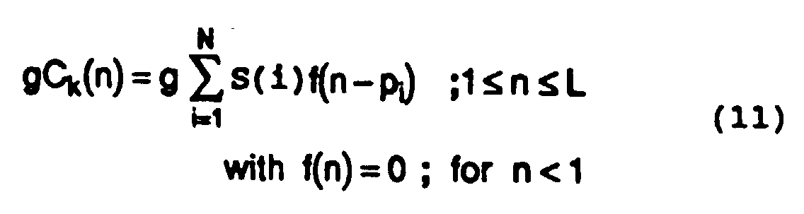
- the component f(n) includes the long term prediction loop.
- ⁇ f(n) impulse response of F(z) 1 1-bz -T with zero initial state.
- Step 306 The long term predictor 106 is supplied with the signal excitation E + g C k to compute the component E of this excitation contributed by the long term prediction (parameters LTP) using the proper pitch delay T and gain b.
- the predictor 106 has the same transfer function as the long term predictor 203 of Figure 2.
- Step 307 In this step, the initial state of the perceptual filter 107 is set to the value FS supplied by the initial state extractor 110.
- the difference R-E calculated by a subtractor 121 Figure 1
- the STP parameters are applied to the filter 107 to vary its transfer function in relation to these parameters.
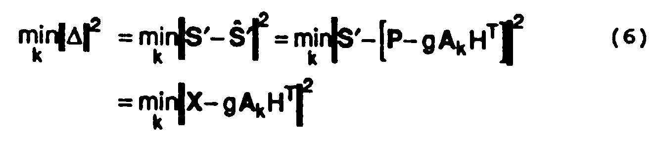
- X S ' - P
- P represents the contribution of the long term prediction (LTP) including "ringing" from the past excitations.
- LTP long term prediction
- the MSE criterion which applies to ⁇ can now be stated in the following matrix notations.
- H accounts for the global filter transfer function F(z)/(1-B(z))A(z ⁇ -1 ). It is an L x L lower triangular Toeplitz matrix formed from the h(n) response.
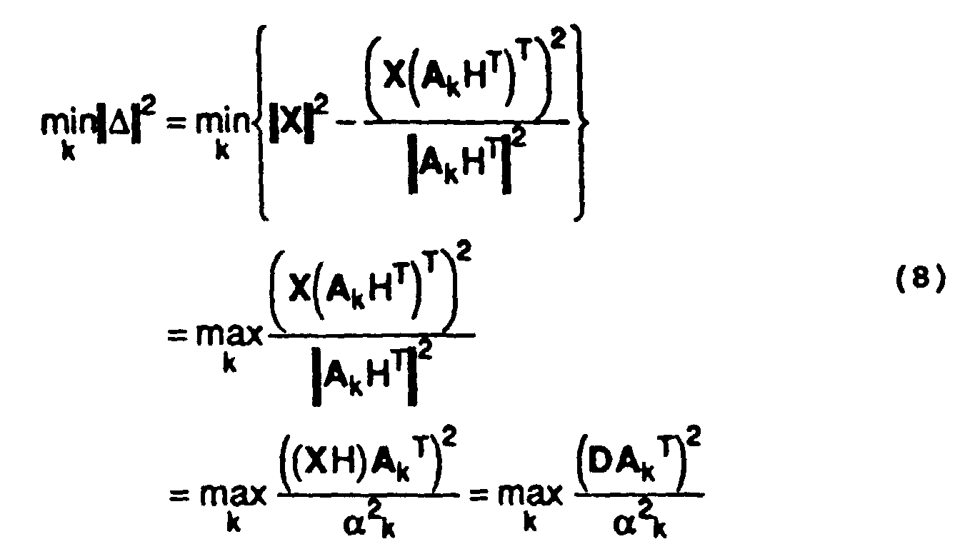
- the term "backward filtering" for this operation comes from the interpretation of (XH) as the filtering of time-reversed X .
- a very fast procedure for calculating the above defined ratio for each codeword A k is described in Figure 5 as a set of N embedded computation loops, N being the number of non zero impulses in the codewords.
- the values for P 2 opt and ⁇ 2 opt are initialized to zero and some large number, respectively.
- Step 310 The global signal excitation signal E + gCk is computed by an adder 120 ( Figure 1).
- the initial state extractor module 110 constituted by a perceptual filter with a transfer function 1/A(z ⁇ -1 ) varying in relation to the STP parameters, subtracts from the residual signal R the signal excitation signal E + g C k for the sole purpose of obtaining the final filter state FS for use as initial state in filter 107 and module 104.
- the set of four parameters STP, LTP, k and g are converted into the proper digital channel format by a multiplexer 111 completing the procedure for encoding a block S of samples of speech signal.
- the present invention provides a fully quantized Algebraic Code Excited Linear Prediction (ACELP) vocoder giving near toll quality at rates ranging from 4 to 16 kbits. This is achieved through the use of the above described dynamic codebook and associated fast search algorithm.
- ACELP Algebraic Code Excited Linear Prediction
- the drastic complexity reduction that the present invention offers when compared to the prior art techniques comes from the fact that the search procedure can be brought back to A k-code space by a modification of the so called backward filtering formulation.
- the search reduces to finding the index k for which the ratio
- a k is a fixed target signal and ak is an energy term the computation of which can be done with very few operations by codeword when N, the number of non zero components of the codeword A k, is small.
Landscapes
- Engineering & Computer Science (AREA)
- Computational Linguistics (AREA)
- Signal Processing (AREA)
- Health & Medical Sciences (AREA)
- Audiology, Speech & Language Pathology (AREA)
- Human Computer Interaction (AREA)
- Physics & Mathematics (AREA)
- Acoustics & Sound (AREA)
- Multimedia (AREA)
- Compression, Expansion, Code Conversion, And Decoders (AREA)
Abstract
Description
- calculating, for each codeword among a plurality of available algebraic codewords Ak expressed in an algebraic code, a ratio involving the signal D, the codeword Ak, and a transfer function H varying in time with parameters representative of spectral characteristics of the sound signal; and
- selecting among said plurality of available algebraic codewords one particular codeword corresponding to the largest ratio calculated, wherein the selected codeword is representative of a signal excitation to be applied to the synthesis means for synthesizing the sound signal.
- means for calculating, for each codeword among a plurality of available algebraic codewords Ak expressed in an algebraic code, a ratio involving the signal D, the codeword Ak, and a transfer function H varying in time with parameters representative of spectral characteristics of the sound signal; and
- means for selecting among the plurality of available algebraic codewords one particular codeword corresponding to the largest ratio calculated, wherein the selected codeword is representative of a signal excitation to be applied to the synthesis means for synthesizing the sound signal.
- wherein, because of the algebraic-code sparsity, the computation involved in the step of calculating a target ratio is reduced to the sum of only N and N(N+1)/2 terms for the numerator and denominator, respectively, namely


- i = 1, 2, ...N;
- S(i) is the amplitude of the ith non-zero pulse of the algebraic codeword Ak;
- D is a backward-filtered version of an L-sample block of the sound signal;
- pi is the position of the ith non-zero pulse of the algebraic codeword Ak;
- pj is the position of the jth non-zero pulse of the algebraic codeword Ak; and
- U is a Toeplitz matrix of
autocorrelation terms defined by the following
equation:
where:

- m = 1, 2, ...L; and
- h(n) is the impulse response of a transfer function H varying in time with parameters representative of spectral characteristics of the sound signal and taking into account long term prediction parameters characterizing a periodicity of the sound signal.


- i = 1, 2, ...N;
- S(i) is the amplitude of the ith non-zero pulse of the algebraic codeword Ak;
- D is a backward-filtered version of an L-sample block of said sound signal;
- pi is the position of the ith non-zero pulse of the algebraic codeword Ak;
- pj is the position of the jth non-zero pulse of the algebraic codeword Ak; and
- U is a Toeplitz matrix of
autocorrelation terms defined by the following
equation,
where:

- m = 1, 2, ...L
- h(n) is the impulse response of a transfer function H varying in time with parameters representative of spectral characteristics of the sound signal and taking into account long term prediction parameters characterizing a periodicity of the sound signal.



·u(i,j) : autocorrelation of h(n); i.e.:



Claims (36)
- A method of producing an excitation signal to be used by a sound signal synthesis means to synthesize a sound signal, comprising the step of generating a codeword signal in response to an index signal associated to said codeword signal, said signal generating step using an algebraic code to generate said codeword signal,
characterized in that said method further comprises the step of filtering the generated codeword signal to produce said excitation signal, said filtering step comprising processing the codeword signal through a coloring filter having a transfer function varying in time in relation to parameters representative of spectral characteristics of said sound signal to thereby shape frequency characteristics of the excitation signal so as to damp frequencies perceptually annoying a human ear. - A method as defined in claim 1, characterized in that said signal generating step comprises using a sparse algebraic code to generate said codeword signal.
- A method as defined in claim 2, characterized in that said sparse algebraic code has a structure involving N interleaved single-pulse permutation codes.
- A method as defined in claim 1, characterized in that said filtering step comprises varying the transfer function of the coloring filter in relation to linear predictive coding parameters representative of spectral characteristics of said sound signal.
- A dynamic codebook for producing an excitation signal to be used by a sound signal synthesis means to synthesize a sound signal, comprising means for generating a codeword signal in response to an index signal associated to said codeword signal, said meane for generating a codeword signal using an algebraic code to generate said codeword signal,
characterized in that said dynamic codebook further comprises means for filtering the generated codeword signal to produce said excitation signal, said filtering means comprising a coloring filter having a transfer function varying in time in relation to parameters representative of spectral characteristics of said sound signal to thereby shape frequency characteristics of the excitation signal so as to damp frequencies perceptually annoying a human ear. - A codebook as defined in claim 5, characterized in that said means for generating a codeword signal comprises means responsive to a sparse algebraic code to generate said codeword signal.
- A codebook as defined in claim 6, wherein said sparse algebraic code has structure involving N interleaved single-pulse permutation codes.
- A codebook as defined in claim 5, characterized in that said coloring filter has a transfer function varying in time in relation to linear predictive coding parameters representative of spectral characteristics of said sound signal.
- A method of encoding a sound signal in view of subsequently synthesizing said sound signal through an excitation signal produced by the method of claim 1 and applied to a sound signal synthesis means, comprising the steps of:characterized in that said sound signal encoding method further comprises the steps of:whitening said sound signal with a whitening filter to generate a residual signal R;computing a target signal X by processing with a perceptual filter a difference between said residual signal R and a long-term-prediction component E of previously generated segments of said excitation signal; andbackward filtering the target signal X with a backward filter to produce a backward filtered target signal D;calculating, for each codeword among a plurality of available algebraic codewords Ak expressed in an algebraic code, a ratio involving the signal D, the codeword Ak, and a transfer function H varying in time with parameters representative of spectral characteristics of said sound signal and taking into account long term prediction parameters characterizing a periodicity of said sound signal; andselecting among said plurality of available algebraic codewords one particular codeword corresponding to the largest ratio calculated, wherein said selected codeword is representative of an excitation signal to be applied to the synthesis means for synthesizing said sound signal.
- The method of claim 9, characterized in that said ratio calculating step comprises calculating, for each codeword, a ratio comprising a numerator given by the expression P2(k) = (DAk T)2 and a denominator given by the expression αk 2 = | AkHT | 2, where Ak and H are under the form of matrix.
- The method of claim 10, characterized in that it comprises providing codewords Ak each in the form of a waveform comprising a small number of non-zero impulses each of which can occupy different positions in the waveform to thereby enable composition of different codewords.
- The method of claim 11, characterized in that said ratio calculating step comprises using a calculating procedure including embedded loops in which are calculated contributions of the non-zero impulses of the considered algebraic codeword to said numerator and denominator, and in which the calculated contributions are added to previously calculated sum values of said numerator and denominator, respectively.
- The method of claim 12, characterized in that said codeword selecting step comprises processing in an innermost loop of said embedded loops said calculated ratios to determine the largest ratio.
- The method of claim 9, characterized in that it comprises carrying out said backward filtering step in relation to said transfer function H.
- An encoder for encoding a sound signal in view of subsequently synthesizing said sound signal through an excitation signal produced by the dynamic codebook of claim 5 and applied to a sound signal synthesis means, comprising:characterized in that said encoder further comprises:a whitening filter for whitening said sound signal in order to generate a residual signal R;a perceptual filter for computing a target signal X by processing a difference between said residual signal R and a long-term-prediction component E of previously generated segments of said excitation signal; anda backward filter for filtering the target signal X in order to produce a backward filtered target signal D;means for calculating, for each codeword among a plurality of available algebraic codewords Ak expressed in an algebraic code, a ratio involving the signal D, the codeword Ak, and a transfer function H varying in time with parameters representative of spectral characteristics of said sound signal and taking into account long term prediction parameters characterizing a periodicity of said sound signal; andmeans for selecting among said plurality of available algebraic codewords one particular codeword corresponding to the largest ratio calculated, wherein said selected codeword is representative of an excitation signal to be applied to the synthesis means for synthesizing said sound signal.
- The encoder of claim 15, characterized in that said ratio calculating means comprises means for calculating, for each codeword, a ratio comprising a numerator given by the expression P2(k) = (DAk )T 2 and a denominator given by the expression α2k = | AkHT | 2, where Ak and H are under the form of matrix.
- The encoder of claim 16, characterized in that each codeword Ak is a waveform comprising a small number of non-zero impulses each of which can occupy different positions in the waveform to thereby enable composition of different codewords.
- The encoder of claim 17, characterized in that said ratio calculating means comprises means for calculating into a plurality of embedded loops contributions of the non-zero impulses of the considered algebraic codeword to said numerator and denominator and for adding the calculated contributions to previously calculated sum values of said numerator and denominator, respectively.
- The encoder of claim 18, characterized in that said codeword selecting means comprises means for processing in an innermost loop of said embedded loops said calculated ratios to determine the largest ratio.
- The encoder of claim 15, characterized in that said backward filter comprises means for filtering said target signal in relation to said transfer function H.
- An encoding method as recited in claim 9, wherein the sound signal is encoded according to a Code-Excited Linear Prediction technique using a sparse algebraic code to generate an algebraic codeword in the form of an L-sample long waveform comprising a small number N of non-zero pulses each of which is assignable to different positions in the waveform to thereby enable composition of several algebraic codewords Ak;
characterized in that:said step of calculating a ratio comprises calculating a target ratiosaid step of selecting one particular codeword comprises (a) determining the largest target ratio among said calculated target ratios, and (b) extracting an index k corresponding to the largest calculated target ratio and associated to one algebraic codeword Ak being selected;
- wherein, because of the algebraic-code sparsity, the computation involved in the step of calculating a target ratio is reduced to the sum of at most N terms for the numerator and at most N(N+1)/2 terms for the denominator, namely where:
 i = 1, 2, ...N;S(i) is the amplitude of the ith non-zero pulse of the algebraic codeword Ak;D is a backward-filtered version of an L-sample block of said sound signal;pi is the position of the ith non-zero pulse of the algebraic codeword Ak;pj is the position of the jth non-zero pulse of the algebraic codeword Ak; andU is a matrix of autocorrelation terms defined by the following equation:where:
 m = 1, 2, ...L; andh(n) is the impulse response of the transfer function H.
 - An encoding method as recited in claim 21, characterized in that the step of calculating the target ratiocalculating in N successive embedded computation loops contributions of the non-zero pulses of the algebraic codeword Ak to the denominator of the target ratio; andin each of said N successive embedded computation loops adding the calculated contributions to contributions previously calculated.
- An encoding method as recited in claim 22, characterized in that said adding step comprises adding the contributions of the non-zero pulses of the algebraic codeword Ak to the denominator of the target ratio calculated in the embedded computation loops by means of the following equation:in which SS(i,j) = S(i)S(j), said equation being developed as follows:
 where the successive lines represent contributions to the denominator of the target ratio calculated in the successive embedded computation loops, respectively.
- An encoding method as recited in claim 23, characterized in that said N successive embedded computation loops comprise an outermost loop and an innermost loop, and said contribution calculating step comprises calculating the contributions of the non-zero pulses of the algebraic codeword Ak to the denominator of the target ratio from the outermost loop to the innermost loop.
- An encoding method as recited in claim 23, characterized in that it further comprises the step of calculating and pre-storing the terms S2(i) and SS(i,j) = S(i)S(j) prior to the calculation of the target ratio for increasing calculation speed.
- An encoding method as recited in claim 21, characterized in that it further comprises the step of interleaving N single-pulse permutation codes to form said sparse algebraic code.
- An encoding method as recited in claim 21, characterized in that the impulse response h(n) of the transfer function H accounts for
- An encoding method as recited in claim 27, characterized in that said first transfer function F(z) is of the form
- An encoder as recited in claim 15, wherein the sound signal is encoded according to a Code-Excited Linear Prediction technique using a sparse algebraic code to generate an algebraic codeword in the form of an L-sample long waveform comprising a small number N of non-zero pulses each of which is assignable to different positions in the waveform to thereby enable composition of several algebraic codewords Ak;
characterized in that:said ratio calculating means comprises means for calculating a target ratiosaid codeword detecting means comprises (a) means for determining the largest ratio among said calculated target ratios, and (b) means for extracting an index k corresponding to the largest calculated target ratio and associated to one algebraic codeword Ak being selected;
- wherein, because of the algebraic-code sparsity, the computation carried out by said means for calculating a target ratio is reduced to the sum of at most N terms for the numerator and at most N(N+1)/2 terms for the denominator, namely where:
 i = 1, 2, ...N;S(i) is the amplitude of the ith non-zero pulse of the algebraic codeword Ak;D is a backward-filtered version of an L-sample block of said sound signal;pi is the position of the ith non-zero pulse of the algebraic codeword Ak;pj is the position of the jth non-zero pulse of the algebraic codeword Ak; andU is a matrix of autocorrelation terms defined by the following equation,where:
 m = 1, 2, ...Lh(n) is the impulse response of the transfer function H.
 - An encoder as recited in claim 29, characterized in that said means for calculating the target ratio
- An encoder as recited in claim 30, characterized in that each of said N successive embedded computation loops comprises means for adding the contributions of the non-zero pulses of the algebraic codeword Ak to the denominator of the target ratio by means of the following equation:in which SS(i,j) = S(i)S(j), said equation being developed as follows:
 where the successive lines represent contributions to the denominator of the target ratio calculated in the successive embedded computation loops, respectively.
- An encoder as recited in claim 31, characterized in that said N successive embedded computation loops comprise an outermost loop, an innermost loop, and means for calculating the contributions of the non-zero pulses of the algebraic codeword Ak to the denominator of the target ratio from the outermost loop to the innermost loop.
- An encoder as recited in claim 31, characterized in that it further comprises means for calculating and pre-storing the terms S2(i) and SS(i,j) = S(i)S(j) prior to the target ratio calculation for increasing calculation speed.
- An encoder as recited in claim 29, characterized in that said sparse algebraic code consists of a number N of interleaved single-pulse permutation codes.
- An encoder as recited in claim 29, characterized in that the impulse response h(n) of the transfer function H accounts for
- An encoder as recited in claim 35, characterized in that said first transfer function F(z) is of the form
Applications Claiming Priority (3)
| Application Number | Priority Date | Filing Date | Title |
|---|---|---|---|
| CA2010830 | 1990-02-23 | ||
| CA002010830A CA2010830C (en) | 1990-02-23 | 1990-02-23 | Dynamic codebook for efficient speech coding based on algebraic codes |
| PCT/CA1990/000381 WO1991013432A1 (en) | 1990-02-23 | 1990-11-06 | Dynamic codebook for efficient speech coding based on algebraic codes |
Publications (2)
| Publication Number | Publication Date |
|---|---|
| EP0516621A1 EP0516621A1 (en) | 1992-12-09 |
| EP0516621B1 true EP0516621B1 (en) | 1998-03-18 |
Family
ID=4144369
Family Applications (1)
| Application Number | Title | Priority Date | Filing Date |
|---|---|---|---|
| EP90915956A Expired - Lifetime EP0516621B1 (en) | 1990-02-23 | 1990-11-06 | Dynamic codebook for efficient speech coding based on algebraic codes |
Country Status (9)
| Country | Link |
|---|---|
| US (2) | US5444816A (en) |
| EP (1) | EP0516621B1 (en) |
| AT (1) | ATE164252T1 (en) |
| AU (1) | AU6632890A (en) |
| CA (1) | CA2010830C (en) |
| DE (1) | DE69032168T2 (en) |
| DK (1) | DK0516621T3 (en) |
| ES (1) | ES2116270T3 (en) |
| WO (1) | WO1991013432A1 (en) |
Families Citing this family (73)
| Publication number | Priority date | Publication date | Assignee | Title |
|---|---|---|---|---|
| US5754976A (en) * | 1990-02-23 | 1998-05-19 | Universite De Sherbrooke | Algebraic codebook with signal-selected pulse amplitude/position combinations for fast coding of speech |
| US5701392A (en) * | 1990-02-23 | 1997-12-23 | Universite De Sherbrooke | Depth-first algebraic-codebook search for fast coding of speech |
| CA2010830C (en) * | 1990-02-23 | 1996-06-25 | Jean-Pierre Adoul | Dynamic codebook for efficient speech coding based on algebraic codes |
| FR2668288B1 (en) * | 1990-10-19 | 1993-01-15 | Di Francesco Renaud | LOW-THROUGHPUT TRANSMISSION METHOD BY CELP CODING OF A SPEECH SIGNAL AND CORRESPONDING SYSTEM. |
| US5233660A (en) * | 1991-09-10 | 1993-08-03 | At&T Bell Laboratories | Method and apparatus for low-delay celp speech coding and decoding |
| US5621852A (en) * | 1993-12-14 | 1997-04-15 | Interdigital Technology Corporation | Efficient codebook structure for code excited linear prediction coding |
| US5699477A (en) * | 1994-11-09 | 1997-12-16 | Texas Instruments Incorporated | Mixed excitation linear prediction with fractional pitch |
| FR2729245B1 (en) * | 1995-01-06 | 1997-04-11 | Lamblin Claude | LINEAR PREDICTION SPEECH CODING AND EXCITATION BY ALGEBRIC CODES |
| US5664053A (en) * | 1995-04-03 | 1997-09-02 | Universite De Sherbrooke | Predictive split-matrix quantization of spectral parameters for efficient coding of speech |
| US5822724A (en) * | 1995-06-14 | 1998-10-13 | Nahumi; Dror | Optimized pulse location in codebook searching techniques for speech processing |
| GB9512284D0 (en) * | 1995-06-16 | 1995-08-16 | Nokia Mobile Phones Ltd | Speech Synthesiser |
| TW321810B (en) * | 1995-10-26 | 1997-12-01 | Sony Co Ltd | |
| EP0773533B1 (en) * | 1995-11-09 | 2000-04-26 | Nokia Mobile Phones Ltd. | Method of synthesizing a block of a speech signal in a CELP-type coder |
| JP3137176B2 (en) * | 1995-12-06 | 2001-02-19 | 日本電気株式会社 | Audio coding device |
| US5751901A (en) * | 1996-07-31 | 1998-05-12 | Qualcomm Incorporated | Method for searching an excitation codebook in a code excited linear prediction (CELP) coder |
| DE19641619C1 (en) * | 1996-10-09 | 1997-06-26 | Nokia Mobile Phones Ltd | Frame synthesis for speech signal in code excited linear predictor |
| CN102129862B (en) * | 1996-11-07 | 2013-05-29 | 松下电器产业株式会社 | Noise reduction device and sound encoding device including noise reduction device |
| US5960389A (en) | 1996-11-15 | 1999-09-28 | Nokia Mobile Phones Limited | Methods for generating comfort noise during discontinuous transmission |
| FI964975A7 (en) * | 1996-12-12 | 1998-06-13 | Nokia Mobile Phones Ltd | Method and device for encoding speech |
| FI114248B (en) | 1997-03-14 | 2004-09-15 | Nokia Corp | Method and apparatus for audio coding and audio decoding |
| JP3064947B2 (en) * | 1997-03-26 | 2000-07-12 | 日本電気株式会社 | Audio / musical sound encoding and decoding device |
| FI113903B (en) | 1997-05-07 | 2004-06-30 | Nokia Corp | Speech coding |
| GB2326724B (en) * | 1997-06-25 | 2002-01-09 | Marconi Instruments Ltd | A spectrum analyser |
| US5924062A (en) * | 1997-07-01 | 1999-07-13 | Nokia Mobile Phones | ACLEP codec with modified autocorrelation matrix storage and search |
| US5913187A (en) * | 1997-08-29 | 1999-06-15 | Nortel Networks Corporation | Nonlinear filter for noise suppression in linear prediction speech processing devices |
| US6029125A (en) * | 1997-09-02 | 2000-02-22 | Telefonaktiebolaget L M Ericsson, (Publ) | Reducing sparseness in coded speech signals |
| EP1267330B1 (en) * | 1997-09-02 | 2005-01-19 | Telefonaktiebolaget LM Ericsson (publ) | Reducing sparseness in coded speech signals |
| US6170033B1 (en) * | 1997-09-30 | 2001-01-02 | Intel Corporation | Forwarding causes of non-maskable interrupts to the interrupt handler |
| FI973873A7 (en) | 1997-10-02 | 1999-04-03 | Nokia Mobile Phones Ltd | Speech coding |
| EP0967594B1 (en) * | 1997-10-22 | 2006-12-13 | Matsushita Electric Industrial Co., Ltd. | Sound encoder and sound decoder |
| US6385576B2 (en) * | 1997-12-24 | 2002-05-07 | Kabushiki Kaisha Toshiba | Speech encoding/decoding method using reduced subframe pulse positions having density related to pitch |
| FI980132A7 (en) | 1998-01-21 | 1999-07-22 | Nokia Mobile Phones Ltd | Adaptive post-filter |
| US5963897A (en) * | 1998-02-27 | 1999-10-05 | Lernout & Hauspie Speech Products N.V. | Apparatus and method for hybrid excited linear prediction speech encoding |
| FI113571B (en) | 1998-03-09 | 2004-05-14 | Nokia Corp | speech Coding |
| JP3180762B2 (en) * | 1998-05-11 | 2001-06-25 | 日本電気株式会社 | Audio encoding device and audio decoding device |
| WO1999065017A1 (en) * | 1998-06-09 | 1999-12-16 | Matsushita Electric Industrial Co., Ltd. | Speech coding apparatus and speech decoding apparatus |
| CA2252170A1 (en) | 1998-10-27 | 2000-04-27 | Bruno Bessette | A method and device for high quality coding of wideband speech and audio signals |
| US6311154B1 (en) | 1998-12-30 | 2001-10-30 | Nokia Mobile Phones Limited | Adaptive windows for analysis-by-synthesis CELP-type speech coding |
| JP4173940B2 (en) * | 1999-03-05 | 2008-10-29 | 松下電器産業株式会社 | Speech coding apparatus and speech coding method |
| US7272553B1 (en) * | 1999-09-08 | 2007-09-18 | 8X8, Inc. | Varying pulse amplitude multi-pulse analysis speech processor and method |
| CA2290037A1 (en) | 1999-11-18 | 2001-05-18 | Voiceage Corporation | Gain-smoothing amplifier device and method in codecs for wideband speech and audio signals |
| FR2802329B1 (en) * | 1999-12-08 | 2003-03-28 | France Telecom | PROCESS FOR PROCESSING AT LEAST ONE AUDIO CODE BINARY FLOW ORGANIZED IN THE FORM OF FRAMES |
| US7363219B2 (en) * | 2000-09-22 | 2008-04-22 | Texas Instruments Incorporated | Hybrid speech coding and system |
| CA2327041A1 (en) * | 2000-11-22 | 2002-05-22 | Voiceage Corporation | A method for indexing pulse positions and signs in algebraic codebooks for efficient coding of wideband signals |
| US6766289B2 (en) | 2001-06-04 | 2004-07-20 | Qualcomm Incorporated | Fast code-vector searching |
| US6789059B2 (en) | 2001-06-06 | 2004-09-07 | Qualcomm Incorporated | Reducing memory requirements of a codebook vector search |
| US7236928B2 (en) * | 2001-12-19 | 2007-06-26 | Ntt Docomo, Inc. | Joint optimization of speech excitation and filter parameters |
| CA2388439A1 (en) * | 2002-05-31 | 2003-11-30 | Voiceage Corporation | A method and device for efficient frame erasure concealment in linear predictive based speech codecs |
| CA2392640A1 (en) * | 2002-07-05 | 2004-01-05 | Voiceage Corporation | A method and device for efficient in-based dim-and-burst signaling and half-rate max operation in variable bit-rate wideband speech coding for cdma wireless systems |
| US7698132B2 (en) * | 2002-12-17 | 2010-04-13 | Qualcomm Incorporated | Sub-sampled excitation waveform codebooks |
| WO2004090870A1 (en) | 2003-04-04 | 2004-10-21 | Kabushiki Kaisha Toshiba | Method and apparatus for encoding or decoding wide-band audio |
| RU2316059C2 (en) * | 2003-05-01 | 2008-01-27 | Нокиа Корпорейшн | Method and device for quantizing amplification in broadband speech encoding with alternating bitrate |
| CN1303584C (en) * | 2003-09-29 | 2007-03-07 | 摩托罗拉公司 | Sound catalog coding for articulated voice synthesizing |
| SG123639A1 (en) | 2004-12-31 | 2006-07-26 | St Microelectronics Asia | A system and method for supporting dual speech codecs |
| JPWO2007037359A1 (en) * | 2005-09-30 | 2009-04-16 | パナソニック株式会社 | Speech coding apparatus and speech coding method |
| WO2007066771A1 (en) * | 2005-12-09 | 2007-06-14 | Matsushita Electric Industrial Co., Ltd. | Fixed code book search device and fixed code book search method |
| US8255207B2 (en) * | 2005-12-28 | 2012-08-28 | Voiceage Corporation | Method and device for efficient frame erasure concealment in speech codecs |
| JP3981399B1 (en) * | 2006-03-10 | 2007-09-26 | 松下電器産業株式会社 | Fixed codebook search apparatus and fixed codebook search method |
| US20080120098A1 (en) * | 2006-11-21 | 2008-05-22 | Nokia Corporation | Complexity Adjustment for a Signal Encoder |
| CN100530357C (en) * | 2007-07-11 | 2009-08-19 | 华为技术有限公司 | Method for searching fixed code book and searcher |
| JP5264913B2 (en) * | 2007-09-11 | 2013-08-14 | ヴォイスエイジ・コーポレーション | Method and apparatus for fast search of algebraic codebook in speech and audio coding |
| CN100578619C (en) * | 2007-11-05 | 2010-01-06 | 华为技术有限公司 | Encoding Methods and Encoders |
| EP2148528A1 (en) * | 2008-07-24 | 2010-01-27 | Oticon A/S | Adaptive long-term prediction filter for adaptive whitening |
| US20100153100A1 (en) * | 2008-12-11 | 2010-06-17 | Electronics And Telecommunications Research Institute | Address generator for searching algebraic codebook |
| US20110273268A1 (en) * | 2010-05-10 | 2011-11-10 | Fred Bassali | Sparse coding systems for highly secure operations of garage doors, alarms and remote keyless entry |
| CN102623012B (en) * | 2011-01-26 | 2014-08-20 | 华为技术有限公司 | Vector joint coding and decoding method, and codec |
| PL3444818T3 (en) | 2012-10-05 | 2023-08-21 | Fraunhofer-Gesellschaft zur Förderung der angewandten Forschung e.V. | An apparatus for encoding a speech signal employing acelp in the autocorrelation domain |
| EP3011561B1 (en) * | 2013-06-21 | 2017-05-03 | Fraunhofer-Gesellschaft zur Förderung der angewandten Forschung e.V. | Apparatus and method for improved signal fade out in different domains during error concealment |
| ES3042587T3 (en) * | 2013-10-18 | 2025-11-21 | Fraunhofer Ges Forschung | Concept of encoding an audio signal and decoding an audio signal using deterministic and noise like information |
| PL3058568T3 (en) | 2013-10-18 | 2021-07-05 | Fraunhofer Gesellschaft zur Förderung der angewandten Forschung e.V. | Concept for encoding an audio signal and decoding an audio signal using speech related spectral shaping information |
| US20170069306A1 (en) * | 2015-09-04 | 2017-03-09 | Foundation of the Idiap Research Institute (IDIAP) | Signal processing method and apparatus based on structured sparsity of phonological features |
| EP4292295A4 (en) | 2021-02-11 | 2025-02-26 | Microsoft Technology Licensing, LLC | MULTI-CHANNEL SPEECH COMPRESSION SYSTEM AND METHOD |
| CN113948085B (en) * | 2021-12-22 | 2022-03-25 | 中国科学院自动化研究所 | Speech recognition method, system, electronic device and storage medium |
Family Cites Families (33)
| Publication number | Priority date | Publication date | Assignee | Title |
|---|---|---|---|---|
| US4401855A (en) * | 1980-11-28 | 1983-08-30 | The Regents Of The University Of California | Apparatus for the linear predictive coding of human speech |
| US4486899A (en) * | 1981-03-17 | 1984-12-04 | Nippon Electric Co., Ltd. | System for extraction of pole parameter values |
| WO1983003917A1 (en) * | 1982-04-29 | 1983-11-10 | Massachusetts Institute Of Technology | Voice encoder and synthesizer |
| US4625286A (en) * | 1982-05-03 | 1986-11-25 | Texas Instruments Incorporated | Time encoding of LPC roots |
| US4520499A (en) * | 1982-06-25 | 1985-05-28 | Milton Bradley Company | Combination speech synthesis and recognition apparatus |
| JPS5922165A (en) * | 1982-07-28 | 1984-02-04 | Nippon Telegr & Teleph Corp <Ntt> | Address controlling circuit |
| EP0111612B1 (en) * | 1982-11-26 | 1987-06-24 | International Business Machines Corporation | Speech signal coding method and apparatus |
| US4764963A (en) * | 1983-04-12 | 1988-08-16 | American Telephone And Telegraph Company, At&T Bell Laboratories | Speech pattern compression arrangement utilizing speech event identification |
| US4667340A (en) * | 1983-04-13 | 1987-05-19 | Texas Instruments Incorporated | Voice messaging system with pitch-congruent baseband coding |
| DE3335358A1 (en) * | 1983-09-29 | 1985-04-11 | Siemens AG, 1000 Berlin und 8000 München | METHOD FOR DETERMINING LANGUAGE SPECTRES FOR AUTOMATIC VOICE RECOGNITION AND VOICE ENCODING |
| US4799261A (en) * | 1983-11-03 | 1989-01-17 | Texas Instruments Incorporated | Low data rate speech encoding employing syllable duration patterns |
| US4724535A (en) * | 1984-04-17 | 1988-02-09 | Nec Corporation | Low bit-rate pattern coding with recursive orthogonal decision of parameters |
| US4680797A (en) * | 1984-06-26 | 1987-07-14 | The United States Of America As Represented By The Secretary Of The Air Force | Secure digital speech communication |
| US4742550A (en) * | 1984-09-17 | 1988-05-03 | Motorola, Inc. | 4800 BPS interoperable relp system |
| CA1252568A (en) * | 1984-12-24 | 1989-04-11 | Kazunori Ozawa | Low bit-rate pattern encoding and decoding capable of reducing an information transmission rate |
| US4858115A (en) * | 1985-07-31 | 1989-08-15 | Unisys Corporation | Loop control mechanism for scientific processor |
| IT1184023B (en) * | 1985-12-17 | 1987-10-22 | Cselt Centro Studi Lab Telecom | PROCEDURE AND DEVICE FOR CODING AND DECODING THE VOICE SIGNAL BY SUB-BAND ANALYSIS AND VECTORARY QUANTIZATION WITH DYNAMIC ALLOCATION OF THE CODING BITS |
| US4720861A (en) * | 1985-12-24 | 1988-01-19 | Itt Defense Communications A Division Of Itt Corporation | Digital speech coding circuit |
| US4797926A (en) * | 1986-09-11 | 1989-01-10 | American Telephone And Telegraph Company, At&T Bell Laboratories | Digital speech vocoder |
| US4771465A (en) * | 1986-09-11 | 1988-09-13 | American Telephone And Telegraph Company, At&T Bell Laboratories | Digital speech sinusoidal vocoder with transmission of only subset of harmonics |
| US4873723A (en) * | 1986-09-18 | 1989-10-10 | Nec Corporation | Method and apparatus for multi-pulse speech coding |
| US4797925A (en) * | 1986-09-26 | 1989-01-10 | Bell Communications Research, Inc. | Method for coding speech at low bit rates |
| IT1195350B (en) * | 1986-10-21 | 1988-10-12 | Cselt Centro Studi Lab Telecom | PROCEDURE AND DEVICE FOR THE CODING AND DECODING OF THE VOICE SIGNAL BY EXTRACTION OF PARA METERS AND TECHNIQUES OF VECTOR QUANTIZATION |
| US4868867A (en) * | 1987-04-06 | 1989-09-19 | Voicecraft Inc. | Vector excitation speech or audio coder for transmission or storage |
| US4815134A (en) * | 1987-09-08 | 1989-03-21 | Texas Instruments Incorporated | Very low rate speech encoder and decoder |
| IL84902A (en) * | 1987-12-21 | 1991-12-15 | D S P Group Israel Ltd | Digital autocorrelation system for detecting speech in noisy audio signal |
| US4817157A (en) * | 1988-01-07 | 1989-03-28 | Motorola, Inc. | Digital speech coder having improved vector excitation source |
| US5097508A (en) * | 1989-08-31 | 1992-03-17 | Codex Corporation | Digital speech coder having improved long term lag parameter determination |
| US5307441A (en) * | 1989-11-29 | 1994-04-26 | Comsat Corporation | Wear-toll quality 4.8 kbps speech codec |
| CA2010830C (en) * | 1990-02-23 | 1996-06-25 | Jean-Pierre Adoul | Dynamic codebook for efficient speech coding based on algebraic codes |
| US5293449A (en) * | 1990-11-23 | 1994-03-08 | Comsat Corporation | Analysis-by-synthesis 2,4 kbps linear predictive speech codec |
| US5396576A (en) * | 1991-05-22 | 1995-03-07 | Nippon Telegraph And Telephone Corporation | Speech coding and decoding methods using adaptive and random code books |
| US5233660A (en) * | 1991-09-10 | 1993-08-03 | At&T Bell Laboratories | Method and apparatus for low-delay celp speech coding and decoding |
-
1990
- 1990-02-23 CA CA002010830A patent/CA2010830C/en not_active Expired - Lifetime
- 1990-11-06 US US07/927,528 patent/US5444816A/en not_active Expired - Lifetime
- 1990-11-06 DK DK90915956T patent/DK0516621T3/en active
- 1990-11-06 DE DE69032168T patent/DE69032168T2/en not_active Expired - Lifetime
- 1990-11-06 AT AT90915956T patent/ATE164252T1/en not_active IP Right Cessation
- 1990-11-06 EP EP90915956A patent/EP0516621B1/en not_active Expired - Lifetime
- 1990-11-06 AU AU66328/90A patent/AU6632890A/en not_active Abandoned
- 1990-11-06 WO PCT/CA1990/000381 patent/WO1991013432A1/en not_active Ceased
- 1990-11-06 ES ES90915956T patent/ES2116270T3/en not_active Expired - Lifetime
-
1995
- 1995-05-11 US US08/438,703 patent/US5699482A/en not_active Expired - Lifetime
Non-Patent Citations (1)
| Title |
|---|
| Tzeng: "Multipulse excitation codebook design and fast search methods for CELP speech coding", pages 590-594 * |
Also Published As
| Publication number | Publication date |
|---|---|
| ATE164252T1 (en) | 1998-04-15 |
| ES2116270T3 (en) | 1998-07-16 |
| DK0516621T3 (en) | 1999-01-11 |
| EP0516621A1 (en) | 1992-12-09 |
| AU6632890A (en) | 1991-09-18 |
| US5699482A (en) | 1997-12-16 |
| US5444816A (en) | 1995-08-22 |
| CA2010830C (en) | 1996-06-25 |
| WO1991013432A1 (en) | 1991-09-05 |
| DE69032168D1 (en) | 1998-04-23 |
| CA2010830A1 (en) | 1991-08-23 |
| DE69032168T2 (en) | 1998-10-08 |
Similar Documents
| Publication | Publication Date | Title |
|---|---|---|
| US5699482A (en) | Fast sparse-algebraic-codebook search for efficient speech coding | |
| US4868867A (en) | Vector excitation speech or audio coder for transmission or storage | |
| US5717824A (en) | Adaptive speech coder having code excited linear predictor with multiple codebook searches | |
| US5359696A (en) | Digital speech coder having improved sub-sample resolution long-term predictor | |
| US6782359B2 (en) | Determining linear predictive coding filter parameters for encoding a voice signal | |
| EP0450064B2 (en) | Digital speech coder having improved sub-sample resolution long-term predictor | |
| JPH0990995A (en) | Speech coding device | |
| US4945565A (en) | Low bit-rate pattern encoding and decoding with a reduced number of excitation pulses | |
| CN1124589C (en) | Method and apparatus for searching excitation codebook in code excited linear prediction (CELP) coder | |
| US5434947A (en) | Method for generating a spectral noise weighting filter for use in a speech coder | |
| US4720865A (en) | Multi-pulse type vocoder | |
| US5839098A (en) | Speech coder methods and systems | |
| EP0379296A2 (en) | A low-delay code-excited linear predictive coder for speech or audio | |
| US5235670A (en) | Multiple impulse excitation speech encoder and decoder | |
| US5692101A (en) | Speech coding method and apparatus using mean squared error modifier for selected speech coder parameters using VSELP techniques | |
| JP3531780B2 (en) | Voice encoding method and decoding method | |
| US7337110B2 (en) | Structured VSELP codebook for low complexity search | |
| JP3095133B2 (en) | Acoustic signal coding method | |
| EP0539103B1 (en) | Generalized analysis-by-synthesis speech coding method and apparatus | |
| JP3296411B2 (en) | Voice encoding method and decoding method | |
| KR950001437B1 (en) | Voice coding method | |
| GB2352949A (en) | Speech coder for communications unit | |
| JP3103108B2 (en) | Audio coding device | |
| JP3984021B2 (en) | Speech / acoustic signal encoding method and electronic apparatus | |
| JP2001100799A (en) | Audio encoding device, audio encoding method, and computer-readable recording medium recording audio encoding algorithm |
Legal Events
| Date | Code | Title | Description |
|---|---|---|---|
| PUAI | Public reference made under article 153(3) epc to a published international application that has entered the european phase |
Free format text: ORIGINAL CODE: 0009012 |
|
| 17P | Request for examination filed |
Effective date: 19920825 |
|
| AK | Designated contracting states |
Kind code of ref document: A1 Designated state(s): AT BE CH DE DK ES FR GB GR IT LI LU NL SE |
|
| 17Q | First examination report despatched |
Effective date: 19950616 |
|
| GRAG | Despatch of communication of intention to grant |
Free format text: ORIGINAL CODE: EPIDOS AGRA |
|
| GRAH | Despatch of communication of intention to grant a patent |
Free format text: ORIGINAL CODE: EPIDOS IGRA |
|
| GRAH | Despatch of communication of intention to grant a patent |
Free format text: ORIGINAL CODE: EPIDOS IGRA |
|
| GRAA | (expected) grant |
Free format text: ORIGINAL CODE: 0009210 |
|
| AK | Designated contracting states |
Kind code of ref document: B1 Designated state(s): AT BE CH DE DK ES FR GB GR IT LI LU NL SE |
|
| REF | Corresponds to: |
Ref document number: 164252 Country of ref document: AT Date of ref document: 19980415 Kind code of ref document: T |
|
| REG | Reference to a national code |
Ref country code: CH Ref legal event code: NV Representative=s name: BOVARD AG PATENTANWAELTE Ref country code: CH Ref legal event code: EP |
|
| REF | Corresponds to: |
Ref document number: 69032168 Country of ref document: DE Date of ref document: 19980423 |
|
| ITF | It: translation for a ep patent filed | ||
| ET | Fr: translation filed | ||
| REG | Reference to a national code |
Ref country code: ES Ref legal event code: FG2A Ref document number: 2116270 Country of ref document: ES Kind code of ref document: T3 |
|
| REG | Reference to a national code |
Ref country code: DK Ref legal event code: T3 |
|
| PLBE | No opposition filed within time limit |
Free format text: ORIGINAL CODE: 0009261 |
|
| STAA | Information on the status of an ep patent application or granted ep patent |
Free format text: STATUS: NO OPPOSITION FILED WITHIN TIME LIMIT |
|
| 26N | No opposition filed | ||
| REG | Reference to a national code |
Ref country code: GB Ref legal event code: IF02 |
|
| PGFP | Annual fee paid to national office [announced via postgrant information from national office to epo] |
Ref country code: AT Payment date: 20091123 Year of fee payment: 20 Ref country code: DK Payment date: 20091118 Year of fee payment: 20 Ref country code: DE Payment date: 20091120 Year of fee payment: 20 Ref country code: ES Payment date: 20091124 Year of fee payment: 20 Ref country code: SE Payment date: 20091120 Year of fee payment: 20 Ref country code: LU Payment date: 20091120 Year of fee payment: 20 Ref country code: CH Payment date: 20091124 Year of fee payment: 20 |
|
| PGFP | Annual fee paid to national office [announced via postgrant information from national office to epo] |
Ref country code: NL Payment date: 20091124 Year of fee payment: 20 |
|
| PGFP | Annual fee paid to national office [announced via postgrant information from national office to epo] |
Ref country code: IT Payment date: 20091126 Year of fee payment: 20 Ref country code: GB Payment date: 20091119 Year of fee payment: 20 Ref country code: FR Payment date: 20091201 Year of fee payment: 20 |
|
| PGFP | Annual fee paid to national office [announced via postgrant information from national office to epo] |
Ref country code: BE Payment date: 20091120 Year of fee payment: 20 Ref country code: GR Payment date: 20091124 Year of fee payment: 20 |
|
| REG | Reference to a national code |
Ref country code: CH Ref legal event code: PL |
|
| REG | Reference to a national code |
Ref country code: NL Ref legal event code: V4 Effective date: 20101106 |
|
| REG | Reference to a national code |
Ref country code: DK Ref legal event code: EUP |
|
| BE20 | Be: patent expired |
Owner name: *UNIVERSITE DE SHERBROOKE Effective date: 20101106 |
|
| REG | Reference to a national code |
Ref country code: GB Ref legal event code: PE20 Expiry date: 20101105 |
|
| PG25 | Lapsed in a contracting state [announced via postgrant information from national office to epo] |
Ref country code: NL Free format text: LAPSE BECAUSE OF EXPIRATION OF PROTECTION Effective date: 20101106 |
|
| EUG | Se: european patent has lapsed | ||
| PG25 | Lapsed in a contracting state [announced via postgrant information from national office to epo] |
Ref country code: GB Free format text: LAPSE BECAUSE OF EXPIRATION OF PROTECTION Effective date: 20101105 |
|
| PG25 | Lapsed in a contracting state [announced via postgrant information from national office to epo] |
Ref country code: DE Free format text: LAPSE BECAUSE OF EXPIRATION OF PROTECTION Effective date: 20101106 |
|
| REG | Reference to a national code |
Ref country code: ES Ref legal event code: FD2A Effective date: 20130801 |
|
| PG25 | Lapsed in a contracting state [announced via postgrant information from national office to epo] |
Ref country code: ES Free format text: LAPSE BECAUSE OF EXPIRATION OF PROTECTION Effective date: 20101107 |