EP0516490A2 - Retractable antenna - Google Patents
Retractable antenna Download PDFInfo
- Publication number
- EP0516490A2 EP0516490A2 EP92305825A EP92305825A EP0516490A2 EP 0516490 A2 EP0516490 A2 EP 0516490A2 EP 92305825 A EP92305825 A EP 92305825A EP 92305825 A EP92305825 A EP 92305825A EP 0516490 A2 EP0516490 A2 EP 0516490A2
- Authority
- EP
- European Patent Office
- Prior art keywords
- antenna element
- elongate
- antenna
- retracted position
- antenna assembly
- Prior art date
- Legal status (The legal status is an assumption and is not a legal conclusion. Google has not performed a legal analysis and makes no representation as to the accuracy of the status listed.)
- Granted
Links
Images
Classifications
-
- H—ELECTRICITY
- H01—ELECTRIC ELEMENTS
- H01Q—ANTENNAS, i.e. RADIO AERIALS
- H01Q1/00—Details of, or arrangements associated with, antennas
- H01Q1/12—Supports; Mounting means
- H01Q1/22—Supports; Mounting means by structural association with other equipment or articles
- H01Q1/24—Supports; Mounting means by structural association with other equipment or articles with receiving set
- H01Q1/241—Supports; Mounting means by structural association with other equipment or articles with receiving set used in mobile communications, e.g. GSM
- H01Q1/242—Supports; Mounting means by structural association with other equipment or articles with receiving set used in mobile communications, e.g. GSM specially adapted for hand-held use
- H01Q1/243—Supports; Mounting means by structural association with other equipment or articles with receiving set used in mobile communications, e.g. GSM specially adapted for hand-held use with built-in antennas
- H01Q1/244—Supports; Mounting means by structural association with other equipment or articles with receiving set used in mobile communications, e.g. GSM specially adapted for hand-held use with built-in antennas extendable from a housing along a given path
Definitions
- This invention relates to an antenna assembly comprising a retractable antenna which may be applied, for example, to a portable radio and, in particular a hand portable radio telephone.
- a radio intended for two-way communication generally operates with either an external fixed rod or retractable antenna, or with an internal antenna.
- the fixed rod type of antenna has a predetermined length. Whilst such antennas can be relatively short, they are not conducive to a compact design nor are they particularly suitable for a radio intended to be carried in a pocket or other receptacle offering restricted space.
- retractable antennas are convenient for this purpose because they can be folded away when the radio is not in use.
- Retractable antennas are commonly of the telescopic tube type, although retractable fixed length antennas are also known.
- Some known portable radios such as that disclosed in US Patent No. 3,087,117 have two antennas, i.e. an internal element together with a retractable element, and are also equipped with means for automatically switching between the two elements according to the physical position of the retractable element.
- the retractable antenna is operable in the extended position, while the internal antenna element becomes operable when the retractable element is in the retracted position.
- both antennas should provide efficient operation under different conditions as appropriate.
- the external antenna element may provide better sensitivity and range performance during normal use, the less efficient internal antenna must provide satisfactory performance during stand-by operation.
- US Patent No. 4,868,576 discloses an antenna for a portable cellular telephone comprising a helical coil at the base of a retractable elongate radiating element.
- the retractable element which extends through the helical coil, has non-conductive portions at its two ends whereby in the extended position the elongate element is capacitively coupled to the helical coil, and in the retracted position the elongate element is substantially decoupled therefrom.
- the helical coil is fixedly mounted on the housing of the radio transceiver.
- an antenna assembly comprising an elongate antenna element mounted in a support and movable between a retracted position and an extended position, and a helical antenna element carried by one end of the elongate antenna element, wherein the elongate antenna element is rendered inactive as a radiating means by movement to the retracted position.
- An antenna assembly in accordance with the present invention provides a compact and convenient dual antenna arrangement which is ideally suited for portable radio applications and which can be manufactured and assembled in a relatively straightforward manner and therefore at low cost.
- Both the antenna elements may be external to the radio housing for optimum radiation performance.
- the elongate antenna element In the extended position the elongate antenna element is active, either alone or in combination with the helical antenna element. In the retracted position the elongate antenna element is rendered inactive so that the more compact helical antenna element alone performs the sole antenna function.
- conductive feed means are coupled to the antenna elements and the elongate antenna element remains connected to said conductive means in the retracted position.
- elongate antenna element encompasses for example a rod type antenna or a coil type antenna having a generally elongate configuration.
- helical is not restricted to a helix having a uniform diameter but is intended to include a coil having a progressively widening diameter, viz. a spiral configuration.
- the helical antenna element is carried by the end of the elongate element remote from the support when the elongate antenna element is in the extended position.
- the antenna support comprises an electrically conductive portion adapted substantially to enclose the elongate antenna element in the retracted position.
- the support comprises a pair of coaxial conductors which provide the feed means to the antenna elements, the elongate antenna element being electrically coupled to the central conductor of the coaxial pair.
- the support may comprise a dielectric tube, the coaxial conductors being provided respectively on the internal and external faces of said dielectric tube.
- the support may comprise a pair of self-supporting concentric cylinders spaced apart, e.g. by an air gap.
- the elongate antenna element may be slidably mounted within the central conductor such that an electrically conductive part, preferably at the inner end thereof, physically contacts, and so is electrically coupled to, the central conductor of the coaxial pair.
- means are disposed at the outer end of the elongate antenna element adjacent the helical antenna element which electrically connect the outer end of the elongate element to the central conductor of the coaxial pair when the elongate antenna element is in the retracted position.
- both ends of the elongate antenna element are coupled to the central conductor when the elongate antenna element is retracted.
- the elongate antenna element is thus rendered inactive as a radiating means and becomes a functional part of the central conductor.
- the helical antenna element may at all times remain electrically coupled to the elongate antenna element.
- common contact means may be provided which electrically connect the helical antenna element to the central conductor of the coaxial pair and which also serve to connect the elongate antenna element to the central conductor of the coaxial pair when the elongate antenna element is in the retracted position.
- the elongate antenna element when retracted, thus becomes a functional part of the coaxial feed to the helical antenna element.
- the contact means suitably comprise a fixed electrical connector present on the support, and a movable electrical connector coupled to the helical antenna element, which movable connector engages the fixed connector when the elongate antenna element is in the retracted position.
- the two connectors may be in the form of respective concentric colletts.
- the portable cellular radio telephone shown in the Figures comprises a housing 1 enclosing a conventional transmitter 2 and receiver 3 coupled respectively via a duplexer 4 to the inner conductor 9 of the coaxial feed to the antenna assembly.
- the coaxial feed is discussed in more detail below.
- the housing 1 also encloses all the other features conventionally found in a portable cellular telephone. Since these aspects are not directly relevant to the instant invention no further details will be given here.
- the antenna assembly provided adjacent the top face of the radio housing 1, comprises a support 5 in the form of a dielectric tube 6.
- the dielectric material of the tube 6 may, for example, be polytetrafluoroethylene (PTFE) or polyethylene.
- the bore of the dielectric tube 6 is provided with a conductive coating 9, for example of nickel plated copper.
- a conductive coating 10, for example of copper is also provided on the outer face of the tube 6.
- the inner and outer conductive coatings 9 and 10 are electrically isolated from each other.
- the inner and outer conductors may alternatively be formed by metal cylinders spaced apart by the dielectric tube 6.
- the outer conductor is electrically connected to ground potential, the ground metallization suitably being provided on the internal faces of the housing 1.
- the support 5 constitutes a coaxial feed to the antenna elements which will now be described.
- the antenna assembly comprises two distinct antenna elements, namely an elongate antenna element 11 and a helical element 12.
- the elongate element comprises a central conductor 7 which may be a solid rod antenna or, alternatively, may be in the form of a close-wound coil which not only enhances flexibility of the elongate element and so reduces the risk of breakage, but also reduces the physical length of the antenna.
- the coil may be made of silver plated beryllium-copper wire.
- the elongate antenna element 11 may be chosen to have an equivalent electrical length, for example, of a quarter-wavelength or three-eights wavelength.
- the conducting portion 7 of the elongate element 11 is enclosed within an insulating sleeve 8 made for example of a flexible plastics material.
- an impedance matching inductor 13 having one end connected to the conductor 7 of the elongate antenna element 11 and the other end connected to an electrically conductive end portion 17 which is in electrical contact with the inner conductor 9 of the dielectric tube 6 (see Figure 3).
- the inductor 13 is present within the insulating sleeve 8.
- the end portion 17 of the elongate antenna element 11 has a circumferential recess 20 which accommodates a radially biassed phosphor bronze spring 21.
- the conductive spring 21 bears against the inner conductor 9 of the support 5 for optimal electrical contact therewith.
- the elongate antenna element 11 is slidably mounted in the bore of the dielectric tube 6 and the conductive spring 21 remains in electrical contact with the inner conductor 9 at all times.
- the end of the elongate antenna element 11 remote from the support 5 carries a helical antenna element 12.
- the helical coil 12 is very compact and has a short physical length but is wider in diameter than the elongate antenna element 11.
- the effective electrical length of the helical antenna element 12 is, for example, a quarter-wavelength.
- the helical coil 12 is embedded in a dome-shaped dielectric encapsulation 14.
- the helical antenna element 12 is permanently electrically connected to the elongate antenna element 11.
- the lower end of the helical coil 12 is also electrically connected to a contact member in the form of a collett 15 which protrudes through the underside of the encapsulation 14.
- a complementary contact in the form of an electrically conductive collett 16 is provided within the upper end of the support 5.
- the collett 16 is provided in the bore of the tube 6 and is electrically connected to the inner conductor 9.
- the support 5 thus acts as a coaxial feed to the elongate antenna element.
- the inner conductor 9 on the dielectric tube is coupled to the radio transmitter 2 and receiver 3 via a duplexer 4. Since the helical antenna element 12 is connected to the elongate antenna element 11 both elements are functionally active as a combined antenna in the extended position.
- the end portion 17 has a narrower portion 22 adjacent the inductor 3 defining a shoulder 23 which abuts the underside of the collett 16 when the antenna is fully extended and so acts as a stop to prevent further withdrawal of the antenna.
- the elongate antenna element In the retracted position shown in Figure 2, the elongate antenna element is substantially entirely enclosed within the coaxial support 5. The conductive end portion 17 nevertheless remains in electrical contact with the inner conductor 9 via the conductive spring 21. Also, the conductive collett 15 depending from the helical antenna element 12 now engages, and hence makes electrical contact with, the complementary conductive collett 16 at the top end of the coaxial support 5. The elongate antenna element is thus rendered inactive as a radiating element in that it essentially becomes part of the central coaxial feed coupled directly to the helical antenna element 12. The helical antenna element is thus electrically coupled directly to the central conductor of the coaxial feed.
- the collett pair 15 and 16 constitutes both a low inductance, low resistance antenna switch and also a detent feature by which the user is able to feel when the antenna is fully retracted.
- the contact between colletts 15 and 16 is broken.
- the outer end of the elongate antenna element is therefore no longer connected to the inner conductor 9 of the coaxial support and the extended portion of the elongate element resumes its function as a radiating antenna element.
- the characteristic impedance Z o of the respective transmission lines which feed the elongate antenna element 11 and the helical antenna element 12 when the elongate antenna element is respectively extended and retracted is substantially the same despite the different nature of the central conductor in the two cases.
- Z o is determined by the equation where ⁇ r is the relative permittivity of the dielectric material of tube 6, d o is the diameter of the outer conductor of the coaxial feed, and d i is the diameter of the inner conductor of the coaxial pair.
- ⁇ r , and d o do not change between the extended and retracted positions. More significantly, however, it will be seen that with the present arrangement d i does not change since the overall diameter of the central conductor 9 is fixed and is not altered by the action of the elongate antenna element 11 sliding internally within the inner conductor 9.
- the helical antenna element 12 may be electrically isolated from the elongate antenna element 11.
- contact means such as a conductive member extending through the insulating sleeve 8 may be provided for electrically connecting the outer end of the elongate element to the inner conductor 9 of the coaxial support when the antenna is in the fully retracted position.
- the collett switch 15, 16 would still be effective to couple the helical antenna element 12 to the central conductor of the coaxial feed.
- the collett pair 15 and 16 thus constitute a low inductance, low resistance antenna switch for the helical antenna element 12. When the antenna is extended the contact between colletts 15 and 16 is broken thus decoupling the helical antenna element.
- the antenna support may comprise a pair of concentric metal cylinders held in spaced relationship by insulating spacers.
- the dielectric may be the air in the gap between the concentric cylinders.
- neither the dielectric tube and the bore thereof, nor the concentric metal cyclinders need be circular in cross-section, but may instead be square, rectangular, oval or indeed any other suitable shape.
Abstract
Description
- This invention relates to an antenna assembly comprising a retractable antenna which may be applied, for example, to a portable radio and, in particular a hand portable radio telephone.
- A radio intended for two-way communication generally operates with either an external fixed rod or retractable antenna, or with an internal antenna. The fixed rod type of antenna has a predetermined length. Whilst such antennas can be relatively short, they are not conducive to a compact design nor are they particularly suitable for a radio intended to be carried in a pocket or other receptacle offering restricted space. On the other hand, retractable antennas are convenient for this purpose because they can be folded away when the radio is not in use. Retractable antennas are commonly of the telescopic tube type, although retractable fixed length antennas are also known.
- Some known portable radios such as that disclosed in US Patent No. 3,087,117 have two antennas, i.e. an internal element together with a retractable element, and are also equipped with means for automatically switching between the two elements according to the physical position of the retractable element. Hence the retractable antenna is operable in the extended position, while the internal antenna element becomes operable when the retractable element is in the retracted position.
- An important consideration with a dual antenna system is that both antennas should provide efficient operation under different conditions as appropriate. For example, while the external antenna element may provide better sensitivity and range performance during normal use, the less efficient internal antenna must provide satisfactory performance during stand-by operation.
- US Patent No. 4,868,576 discloses an antenna for a portable cellular telephone comprising a helical coil at the base of a retractable elongate radiating element. The retractable element, which extends through the helical coil, has non-conductive portions at its two ends whereby in the extended position the elongate element is capacitively coupled to the helical coil, and in the retracted position the elongate element is substantially decoupled therefrom. The helical coil is fixedly mounted on the housing of the radio transceiver.
- According to the present invention there is provided an antenna assembly comprising an elongate antenna element mounted in a support and movable between a retracted position and an extended position, and a helical antenna element carried by one end of the elongate antenna element, wherein the elongate antenna element is rendered inactive as a radiating means by movement to the retracted position.
- An antenna assembly in accordance with the present invention provides a compact and convenient dual antenna arrangement which is ideally suited for portable radio applications and which can be manufactured and assembled in a relatively straightforward manner and therefore at low cost. Both the antenna elements may be external to the radio housing for optimum radiation performance. In the extended position the elongate antenna element is active, either alone or in combination with the helical antenna element. In the retracted position the elongate antenna element is rendered inactive so that the more compact helical antenna element alone performs the sole antenna function. In a preferred embodiment conductive feed means are coupled to the antenna elements and the elongate antenna element remains connected to said conductive means in the retracted position.
- It is noted that the term "elongate antenna element" as used herein encompasses for example a rod type antenna or a coil type antenna having a generally elongate configuration. Also the term "helical" is not restricted to a helix having a uniform diameter but is intended to include a coil having a progressively widening diameter, viz. a spiral configuration.
- By contrast with the antenna configuration disclosed in US Patent No. 4,868,576, in a preferred embodiment of an antenna assembly in accordance with the present invention the helical antenna element is carried by the end of the elongate element remote from the support when the elongate antenna element is in the extended position.
- Suitably the antenna support comprises an electrically conductive portion adapted substantially to enclose the elongate antenna element in the retracted position. Preferably the support comprises a pair of coaxial conductors which provide the feed means to the antenna elements, the elongate antenna element being electrically coupled to the central conductor of the coaxial pair. The support may comprise a dielectric tube, the coaxial conductors being provided respectively on the internal and external faces of said dielectric tube. Alternatively, the support may comprise a pair of self-supporting concentric cylinders spaced apart, e.g. by an air gap. In either case the elongate antenna element may be slidably mounted within the central conductor such that an electrically conductive part, preferably at the inner end thereof, physically contacts, and so is electrically coupled to, the central conductor of the coaxial pair.
- In the preferred embodiment means are disposed at the outer end of the elongate antenna element adjacent the helical antenna element which electrically connect the outer end of the elongate element to the central conductor of the coaxial pair when the elongate antenna element is in the retracted position. Hence both ends of the elongate antenna element are coupled to the central conductor when the elongate antenna element is retracted. The elongate antenna element is thus rendered inactive as a radiating means and becomes a functional part of the central conductor.
- In one embodiment the helical antenna element may at all times remain electrically coupled to the elongate antenna element. In this case common contact means may be provided which electrically connect the helical antenna element to the central conductor of the coaxial pair and which also serve to connect the elongate antenna element to the central conductor of the coaxial pair when the elongate antenna element is in the retracted position. The elongate antenna element, when retracted, thus becomes a functional part of the coaxial feed to the helical antenna element.
- The contact means suitably comprise a fixed electrical connector present on the support, and a movable electrical connector coupled to the helical antenna element, which movable connector engages the fixed connector when the elongate antenna element is in the retracted position. The two connectors may be in the form of respective concentric colletts.
- An embodiment of the invention will now be described, by way of example, with reference to the accompanying drawings in which:
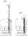
- Figure 1 is a schematic cross-section of a portable cellular radio telephone incorporating an antenna assembly in accordance with the present invention, showing the antenna in the extended position,
- Figure 2 is a schematic cross-section of the portable cellular radio telephone in Figure 1 showing the antenna in the retracted position, and
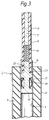
- Figure 3 is an enlarged cross-section showing a portion of the antenna and support in more detail.
- The portable cellular radio telephone shown in the Figures comprises a housing 1 enclosing a
conventional transmitter 2 andreceiver 3 coupled respectively via aduplexer 4 to theinner conductor 9 of the coaxial feed to the antenna assembly. The coaxial feed is discussed in more detail below. - The housing 1 also encloses all the other features conventionally found in a portable cellular telephone. Since these aspects are not directly relevant to the instant invention no further details will be given here.
- The antenna assembly, provided adjacent the top face of the radio housing 1, comprises a support 5 in the form of a
dielectric tube 6. The dielectric material of thetube 6 may, for example, be polytetrafluoroethylene (PTFE) or polyethylene.
The bore of thedielectric tube 6 is provided with aconductive coating 9, for example of nickel plated copper. Aconductive coating 10, for example of copper is also provided on the outer face of thetube 6. The inner and outerconductive coatings dielectric tube 6. The outer conductor is electrically connected to ground potential, the ground metallization suitably being provided on the internal faces of the housing 1. Hence, the support 5 constitutes a coaxial feed to the antenna elements which will now be described. - The antenna assembly comprises two distinct antenna elements, namely an
elongate antenna element 11 and ahelical element 12. The elongate element comprises acentral conductor 7 which may be a solid rod antenna or, alternatively, may be in the form of a close-wound coil which not only enhances flexibility of the elongate element and so reduces the risk of breakage, but also reduces the physical length of the antenna. The coil may be made of silver plated beryllium-copper wire. Theelongate antenna element 11 may be chosen to have an equivalent electrical length, for example, of a quarter-wavelength or three-eights wavelength. The conductingportion 7 of theelongate element 11 is enclosed within aninsulating sleeve 8 made for example of a flexible plastics material. At the base of the elongate antenna element there is provided an impedance matchinginductor 13 having one end connected to theconductor 7 of theelongate antenna element 11 and the other end connected to an electricallyconductive end portion 17 which is in electrical contact with theinner conductor 9 of the dielectric tube 6 (see Figure 3). Theinductor 13 is present within theinsulating sleeve 8. Theend portion 17 of theelongate antenna element 11 has acircumferential recess 20 which accommodates a radially biassedphosphor bronze spring 21. Theconductive spring 21 bears against theinner conductor 9 of the support 5 for optimal electrical contact therewith. - The
elongate antenna element 11 is slidably mounted in the bore of thedielectric tube 6 and theconductive spring 21 remains in electrical contact with theinner conductor 9 at all times. - The end of the
elongate antenna element 11 remote from the support 5 carries ahelical antenna element 12. Thehelical coil 12 is very compact and has a short physical length but is wider in diameter than theelongate antenna element 11. The effective electrical length of thehelical antenna element 12 is, for example, a quarter-wavelength. Thehelical coil 12 is embedded in a dome-shapeddielectric encapsulation 14. - In the present embodiment the
helical antenna element 12 is permanently electrically connected to theelongate antenna element 11. The lower end of thehelical coil 12 is also electrically connected to a contact member in the form of acollett 15 which protrudes through the underside of theencapsulation 14. A complementary contact in the form of an electricallyconductive collett 16 is provided within the upper end of the support 5. Thecollett 16 is provided in the bore of thetube 6 and is electrically connected to theinner conductor 9. - When the antenna is in the extended position as shown in Figure 1, the electrically
conductive end portion 17, which is coupled to the lower end of theimpedance matching inductor 13, makes electrical contact via theconductive spring 21 with theinner conductor 9 on the support 5. The support 5 thus acts as a coaxial feed to the elongate antenna element. As mentioned previously, theinner conductor 9 on the dielectric tube is coupled to theradio transmitter 2 andreceiver 3 via aduplexer 4. Since thehelical antenna element 12 is connected to theelongate antenna element 11 both elements are functionally active as a combined antenna in the extended position. - As can be seen most clearly in Figure 3, the
end portion 17 has anarrower portion 22 adjacent theinductor 3 defining ashoulder 23 which abuts the underside of thecollett 16 when the antenna is fully extended and so acts as a stop to prevent further withdrawal of the antenna. - In the retracted position shown in Figure 2, the elongate antenna element is substantially entirely enclosed within the coaxial support 5. The
conductive end portion 17 nevertheless remains in electrical contact with theinner conductor 9 via theconductive spring 21. Also, theconductive collett 15 depending from thehelical antenna element 12 now engages, and hence makes electrical contact with, the complementaryconductive collett 16 at the top end of the coaxial support 5. The elongate antenna element is thus rendered inactive as a radiating element in that it essentially becomes part of the central coaxial feed coupled directly to thehelical antenna element 12. The helical antenna element is thus electrically coupled directly to the central conductor of the coaxial feed. Thecollett pair colletts inner conductor 9 of the coaxial support and the extended portion of the elongate element resumes its function as a radiating antenna element. - It is noted here that the characteristic impedance Zo of the respective transmission lines which feed the
elongate antenna element 11 and thehelical antenna element 12 when the elongate antenna element is respectively extended and retracted is substantially the same despite the different nature of the central conductor in the two cases. This is because, in the case of a coaxial transmission line with a circular cross-section, Zo is determined by the equation
where εr is the relative permittivity of the dielectric material oftube 6, do is the diameter of the outer conductor of the coaxial feed, and di is the diameter of the inner conductor of the coaxial pair. Clearly εr, and do do not change between the extended and retracted positions. More significantly, however, it will be seen that with the present arrangement di does not change since the overall diameter of thecentral conductor 9 is fixed and is not altered by the action of theelongate antenna element 11 sliding internally within theinner conductor 9. - In an alternative embodiment the
helical antenna element 12 may be electrically isolated from theelongate antenna element 11. In this case contact means such as a conductive member extending through the insulatingsleeve 8 may be provided for electrically connecting the outer end of the elongate element to theinner conductor 9 of the coaxial support when the antenna is in the fully retracted position. In the retracted position thecollett switch helical antenna element 12 to the central conductor of the coaxial feed. Thecollett pair helical antenna element 12. When the antenna is extended the contact betweencolletts elongate antenna element 11 and theinner conductor 9 of the coaxial support whereby the elongate element, which remains electrically coupled at thelower end portion 17 to theinner conductor 9, resumes its function as a radiating antenna. - In view of the foregoing description it will be evident to a person skilled in the art that various modifications may be made within the scope of the present invention. For example, instead of being formed of a solid dielectric tube the antenna support may comprise a pair of concentric metal cylinders held in spaced relationship by insulating spacers. In this case the dielectric may be the air in the gap between the concentric cylinders. Furthermore, it is noted here that neither the dielectric tube and the bore thereof, nor the concentric metal cyclinders need be circular in cross-section, but may instead be square, rectangular, oval or indeed any other suitable shape.
Claims (14)
- An antenna assembly comprising an elongate antenna element mounted in a support and movable between a retracted position and an extended position, and a helical antenna element carried by one end of the elongate antenna element, wherein the elongate antenna element is rendered inactive as a radiating means by movement to the retracted position.
- An antenna assembly as claimed in claim 1, further including conductive feed means coupled to said antenna elements, wherein the elongate antenna element remains connected to said conductive feed means in the retracted position.
- An antenna assembly as claimed in claim 1 or claim 2, wherein the support comprises a pair of coaxial conductors providing said feed means to the antenna elements, the elongate antenna element being electrically coupled to the central conductor of the coaxial pair.
- An antenna assembly as claimed in claim 3, wherein the elongate antenna element is slidably mounted within the central conductor.
- An antenna assembly as claimed in claim 3 or claim 4, wherein means are provided at the end of the elongate antenna element opposite said one end which electrically couple said opposite end of the elongate antenna element to the central conductor of the coaxial pair.
- An antenna assembly as claimed in any of claims 3 to 5, including means disposed at said one end of the elongate antenna element which electrically connect said one end of the elongate antenna element to the central conductor of the coaxial pair when the elongate antenna element is in the retracted position.
- An antenna assembly as claimed in any of claims 3 to 6, wherein the support comprises a dielectric tube and the coaxial conductors are provided respectively on the internal and external faces of said tube.
- An antenna assembly as claimed in any of claims 3 to 6, wherein the coaxial conductors of the support comprise a pair of concentric conductive cylinders in spaced relationship.
- An antenna assembly as claimed in any of claims 3 to 8, including contact means which electrically connect the helical antenna element to the central conductor of the coaxial pair when the elongate antenna element is in the retracted position.
- An antenna assembly as claimed in claim 9, wherein the contact means comprise a fixed electrical connector present on the support, and a movable electrical connector coupled to the helical antenna element, which movable connector engages the fixed connector when the elongate antenna element is in the retracted position.
- An antenna assembly as claimed in claim 10, wherein the fixed connector and the movable connector are in the form of respective concentric colletts.
- An antenna assembly as claimed in any of claims 9 to 11, wherein the contact means also connects the elongate antenna element to the central conductor of the coaxial pair when the elongate antenna element is in the retracted position.
- An antenna assembly as claimed in any of the preceding claims, wherein the helical antenna element is present at the end of the elongate antenna element remote from the support when the elongate antenna element is in the extended position.
- A portable radio transceiver comprising a housing enclosing transmitting and receiver circuitry, and an antenna assembly as claimed in any of the preceding claims, said antenna assembly being coupled to said transmitting and receiving circuitry.
Priority Applications (1)
| Application Number | Priority Date | Filing Date | Title |
|---|---|---|---|
| EP97101332A EP0776061A2 (en) | 1991-07-13 | 1992-06-24 | Retractable antenna |
Applications Claiming Priority (2)
| Application Number | Priority Date | Filing Date | Title |
|---|---|---|---|
| GB9115134A GB2257835B (en) | 1991-07-13 | 1991-07-13 | Retractable antenna |
| GB9115134 | 1991-07-13 |
Related Child Applications (1)
| Application Number | Title | Priority Date | Filing Date |
|---|---|---|---|
| EP97101332.1 Division-Into | 1997-01-29 |
Publications (3)
| Publication Number | Publication Date |
|---|---|
| EP0516490A2 true EP0516490A2 (en) | 1992-12-02 |
| EP0516490A3 EP0516490A3 (en) | 1993-03-24 |
| EP0516490B1 EP0516490B1 (en) | 1997-12-10 |
Family
ID=10698300
Family Applications (2)
| Application Number | Title | Priority Date | Filing Date |
|---|---|---|---|
| EP92305825A Expired - Lifetime EP0516490B1 (en) | 1991-07-13 | 1992-06-24 | Retractable antenna |
| EP97101332A Withdrawn EP0776061A2 (en) | 1991-07-13 | 1992-06-24 | Retractable antenna |
Family Applications After (1)
| Application Number | Title | Priority Date | Filing Date |
|---|---|---|---|
| EP97101332A Withdrawn EP0776061A2 (en) | 1991-07-13 | 1992-06-24 | Retractable antenna |
Country Status (7)
| Country | Link |
|---|---|
| US (1) | US5353036A (en) |
| EP (2) | EP0516490B1 (en) |
| JP (1) | JP3406328B2 (en) |
| AT (1) | ATE161119T1 (en) |
| DE (1) | DE69223451T2 (en) |
| GB (1) | GB2257835B (en) |
| IL (1) | IL102468A (en) |
Cited By (27)
| Publication number | Priority date | Publication date | Assignee | Title |
|---|---|---|---|---|
| WO1994028593A1 (en) * | 1993-05-24 | 1994-12-08 | Allgon Ab | Antenna device for portable equipment |
| EP0632521A1 (en) * | 1993-07-01 | 1995-01-04 | Societe D'applications Generales D'electricite Et De Mecanique Sagem | Flexible telescopic antenna |
| EP0634806A1 (en) * | 1993-07-13 | 1995-01-18 | Kabushiki Kaisha Yokowo | Radio antenna |
| DE4327955A1 (en) * | 1993-08-19 | 1995-02-23 | Siemens Ag | Hand-held radio telephone |
| WO1995008853A1 (en) * | 1993-09-20 | 1995-03-30 | Motorola, Inc. | Antenna arrangement for a wireless communication device |
| US5412393A (en) * | 1993-01-25 | 1995-05-02 | Motorola, Inc. | Retractable antenna assembly with bottom connector |
| US5438339A (en) * | 1993-02-26 | 1995-08-01 | Nec Corporation | Antenna for a radio communication apparatus |
| US5455595A (en) * | 1993-01-29 | 1995-10-03 | Nec Corporation | Antenna for portable radio communication apparatus |
| US5467096A (en) * | 1993-02-25 | 1995-11-14 | Nec Corporation | Antenna for a radio communication apparatus |
| US5541609A (en) * | 1995-03-08 | 1996-07-30 | Virginia Polytechnic Institute And State University | Reduced operator emission exposure antennas for safer hand-held radios and cellular telephones |
| EP0718909A3 (en) * | 1994-12-23 | 1996-08-07 | Nokia Mobile Phones Ltd | |
| US5710567A (en) * | 1995-10-25 | 1998-01-20 | Allgon Ab | Antenna locking device using magnetic attractive elements when antenna is extended |
| WO1998043312A1 (en) * | 1997-03-24 | 1998-10-01 | Telefonaktiebolaget Lm Ericsson | Retractable antenna with shifting electrical length |
| WO1998057390A1 (en) * | 1997-06-10 | 1998-12-17 | Centurion International, Inc. | Retractable 1/2 wave antenna with integral matching section |
| US5940745A (en) * | 1993-03-24 | 1999-08-17 | Nec Corporation | Portable transceiver having retractable antenna and matching circuit |
| WO1999049535A1 (en) * | 1998-03-20 | 1999-09-30 | Ericsson Inc. | Radio frequency antenna with integrated impedance matching element |
| WO1999054959A1 (en) * | 1998-04-16 | 1999-10-28 | Allgon Ab | Antenna means and a handheld radio communication device including such means |
| US6016125A (en) * | 1996-08-29 | 2000-01-18 | Telefonaktiebolaget Lm Ericsson | Antenna device and method for portable radio equipment |
| EP0978897A1 (en) * | 1998-08-07 | 2000-02-09 | Tokin Corporation | Extending whip antenna having a notched stopper |
| EP1069643A2 (en) * | 1994-06-28 | 2001-01-17 | Sony Corporation | Antenna assembly and portable radio apparatus |
| EP1150378A2 (en) * | 2000-04-14 | 2001-10-31 | Nec Corporation | Retractable/extendable antenna for portable radio device |
| US6317086B1 (en) | 1999-02-01 | 2001-11-13 | Mrw Technologies Ltd. | Extendible and contractible wireless antenna |
| CN1079589C (en) * | 1995-09-29 | 2002-02-20 | 摩托罗拉公司 | Aerial assembly for radio communication device |
| US6380897B1 (en) | 1997-05-09 | 2002-04-30 | Nokia Mobile Phones Limited | Portable radio telephone |
| KR100364648B1 (en) * | 1994-09-06 | 2003-03-04 | 소니 가부시끼 가이샤 | antenna |
| US6683007B1 (en) | 1999-03-15 | 2004-01-27 | Nec Corporation | Etching and cleaning methods and etching and cleaning apparatus used therefor |
| US7706847B1 (en) | 1997-05-09 | 2010-04-27 | Nokia Corporation | Portable radio telephone |
Families Citing this family (170)
| Publication number | Priority date | Publication date | Assignee | Title |
|---|---|---|---|---|
| GB9207639D0 (en) * | 1992-04-08 | 1992-05-27 | Nokia Mobile Phones R & D Uk | Radio with retractable antenna |
| JP3457351B2 (en) * | 1992-09-30 | 2003-10-14 | 株式会社東芝 | Portable wireless devices |
| SG46259A1 (en) * | 1993-01-29 | 1998-02-20 | Motorola Inc | Antenna assembly for radio circuit and method thereof |
| JP2574256Y2 (en) * | 1993-02-19 | 1998-06-11 | 松下電器産業株式会社 | Antenna device |
| US6018321A (en) * | 1993-07-20 | 2000-01-25 | Centurion International, Inc. | Variable extended cable antenna for a cellular telephone |
| JPH0786819A (en) * | 1993-09-09 | 1995-03-31 | Mitsubishi Electric Corp | Antenna system |
| JP2974895B2 (en) * | 1993-09-16 | 1999-11-10 | 富士通株式会社 | Portable wireless devices |
| JPH07106825A (en) * | 1993-09-29 | 1995-04-21 | Kimura Denshi Kogyo:Kk | Antenna system for portable radio equipment |
| US5617105A (en) * | 1993-09-29 | 1997-04-01 | Ntt Mobile Communications Network, Inc. | Antenna equipment |
| JP3059336B2 (en) * | 1994-04-06 | 2000-07-04 | 三菱電機株式会社 | Antenna device and mobile communication device |
| US5504494A (en) * | 1994-11-25 | 1996-04-02 | Motorola, Inc. | Multi-stage antenna |
| US5659889A (en) * | 1995-01-04 | 1997-08-19 | Centurion International, Inc. | Radio with antenna connector having high and low impedance points |
| KR960030478A (en) * | 1995-01-27 | 1996-08-17 | 김광호 | Antenna of wireless device |
| SE9500456D0 (en) * | 1995-02-08 | 1995-02-08 | Allgon Ab | High-efficient compact antenna means for a personal telephone with a small receiving depth |
| US5640689A (en) * | 1995-03-31 | 1997-06-17 | Compaq Computer Corp. | Communications apparatus with antenna switching based on antenna rotation |
| US5594457A (en) * | 1995-04-21 | 1997-01-14 | Centurion International, Inc. | Retractable antenna |
| KR100194422B1 (en) * | 1995-04-27 | 1999-06-15 | 김광호 | Antenna connection device of portable wireless device |
| US5635943A (en) * | 1995-10-16 | 1997-06-03 | Matsushita Communication Industrial Corp. Of America | Transceiver having retractable antenna assembly |
| US5686927A (en) * | 1995-11-03 | 1997-11-11 | Centurion International, Inc. | Retractable antenna |
| US5717408A (en) * | 1995-12-18 | 1998-02-10 | Centurion International, Inc. | Retractable antenna for a cellular telephone |
| US5739792A (en) * | 1995-12-22 | 1998-04-14 | Motorola, Inc. | Wireless communication device with electrical contacts |
| TW353833B (en) * | 1995-12-22 | 1999-03-01 | Motorola Inc | Wireless communication device having a reconfigurable matching circuit |
| US5892483A (en) * | 1996-03-15 | 1999-04-06 | Ericsson Inc. | Dual antenna arrangement for portable transceiver |
| US5748150A (en) * | 1996-04-04 | 1998-05-05 | Ericsson, Inc. | Retractable antenna assembly |
| US5900846A (en) * | 1996-08-21 | 1999-05-04 | Ericsson, Inc. | Flexible telescoping antenna and method of constructing the same |
| US6112102A (en) * | 1996-10-04 | 2000-08-29 | Telefonaktiebolaget Lm Ericsson | Multi-band non-uniform helical antennas |
| US5963871A (en) * | 1996-10-04 | 1999-10-05 | Telefonaktiebolaget Lm Ericsson | Retractable multi-band antennas |
| US5987311A (en) * | 1996-12-27 | 1999-11-16 | Ericsson Inc. | Apparatus for enabling a keypad in response to antenna extension |
| US5808586A (en) * | 1997-02-19 | 1998-09-15 | Motorola, Inc. | Side-by-side coil-fed antenna for a portable radio |
| US5945964A (en) * | 1997-02-19 | 1999-08-31 | Motorola, Inc. | Multi-band antenna structure for a portable radio |
| US5914689A (en) * | 1997-06-25 | 1999-06-22 | Centurion Intl., Inc. | Antenna for a portable, wireless communication device |
| US6031495A (en) * | 1997-07-02 | 2000-02-29 | Centurion Intl., Inc. | Antenna system for reducing specific absorption rates |
| US6198448B1 (en) | 1997-07-29 | 2001-03-06 | Tokin Corporation | Lightweight antenna assembly comprising a whip antenna and a helical antenna mounted on a top end of the whip antenna |
| US6052088A (en) * | 1997-08-26 | 2000-04-18 | Centurion International, Inc. | Multi-band antenna |
| US6329962B2 (en) | 1998-08-04 | 2001-12-11 | Telefonaktiebolaget Lm Ericsson (Publ) | Multiple band, multiple branch antenna for mobile phone |
| JP3041520B2 (en) | 1998-01-19 | 2000-05-15 | 株式会社トーキン | antenna |
| JPH11298219A (en) | 1998-04-10 | 1999-10-29 | Tokin Corp | Antenna and portable radio equipment using the antenna |
| JP2000049519A (en) * | 1998-05-27 | 2000-02-18 | Ace Technol Co Ltd | Antenna device for portable communication terminal |
| EP1027750A1 (en) * | 1998-06-12 | 2000-08-16 | Hughes Electronics Corporation | Slidable connection for a retractable antenna to a mobile radio |
| US6353443B1 (en) | 1998-07-09 | 2002-03-05 | Telefonaktiebolaget Lm Ericsson (Publ) | Miniature printed spiral antenna for mobile terminals |
| US6166694A (en) * | 1998-07-09 | 2000-12-26 | Telefonaktiebolaget Lm Ericsson (Publ) | Printed twin spiral dual band antenna |
| SE9802772D0 (en) * | 1998-08-19 | 1998-08-19 | Allgon Ab | Antenna device comprising sliding connector means |
| JP2000091827A (en) | 1998-09-07 | 2000-03-31 | Ace Technol Co Ltd | Helical antenna for portable communication terminal equipment using ceramic dielectric and manufacture of the same |
| US6002372A (en) * | 1998-09-09 | 1999-12-14 | Centurion International, Inc. | Collapsible antenna |
| US6075489A (en) * | 1998-09-09 | 2000-06-13 | Centurion Intl., Inc. | Collapsible antenna |
| KR100345534B1 (en) * | 1998-10-07 | 2002-10-25 | 삼성전자 주식회사 | Antenna unit installed on the flip cover in flip-up phones |
| JP2000151240A (en) * | 1998-11-11 | 2000-05-30 | Matsushita Electric Ind Co Ltd | Antenna holding device |
| US6166696A (en) * | 1998-11-30 | 2000-12-26 | T&M Antennas | Dual radiator galvanic contact antenna for portable communicator |
| US6343208B1 (en) | 1998-12-16 | 2002-01-29 | Telefonaktiebolaget Lm Ericsson (Publ) | Printed multi-band patch antenna |
| US6215446B1 (en) * | 1999-07-23 | 2001-04-10 | Centurion Wireless Technologies, Inc. | Snap-in antenna |
| US6198443B1 (en) | 1999-07-30 | 2001-03-06 | Centurion Intl., Inc. | Dual band antenna for cellular communications |
| KR100387039B1 (en) * | 2001-03-24 | 2003-06-12 | 삼성전자주식회사 | Retractrable/extendable antenna unit with conductive tube for portable radiotelephone |
| US20040227676A1 (en) * | 2003-05-16 | 2004-11-18 | Youn-Sung Kim | Antenna for cellular phone |
| US7515108B2 (en) * | 2003-11-04 | 2009-04-07 | Samsung Electronics Co., Ltd. | Antenna unit with incorporated TV and communication antennas for portable communication terminals and signal receiving method thereof |
| US20060154708A1 (en) * | 2005-01-13 | 2006-07-13 | Brehn Corporation | Personal portable external cell phone antenna |
| TW200743259A (en) * | 2006-05-15 | 2007-11-16 | Wha Yu Ind Co Ltd | Installation method of wireless signal transceiver antenna and its structure |
| US9999038B2 (en) | 2013-05-31 | 2018-06-12 | At&T Intellectual Property I, L.P. | Remote distributed antenna system |
| US9525524B2 (en) | 2013-05-31 | 2016-12-20 | At&T Intellectual Property I, L.P. | Remote distributed antenna system |
| US8897697B1 (en) | 2013-11-06 | 2014-11-25 | At&T Intellectual Property I, Lp | Millimeter-wave surface-wave communications |
| US9768833B2 (en) | 2014-09-15 | 2017-09-19 | At&T Intellectual Property I, L.P. | Method and apparatus for sensing a condition in a transmission medium of electromagnetic waves |
| US10063280B2 (en) | 2014-09-17 | 2018-08-28 | At&T Intellectual Property I, L.P. | Monitoring and mitigating conditions in a communication network |
| US9615269B2 (en) | 2014-10-02 | 2017-04-04 | At&T Intellectual Property I, L.P. | Method and apparatus that provides fault tolerance in a communication network |
| US9685992B2 (en) | 2014-10-03 | 2017-06-20 | At&T Intellectual Property I, L.P. | Circuit panel network and methods thereof |
| US9503189B2 (en) | 2014-10-10 | 2016-11-22 | At&T Intellectual Property I, L.P. | Method and apparatus for arranging communication sessions in a communication system |
| US9973299B2 (en) | 2014-10-14 | 2018-05-15 | At&T Intellectual Property I, L.P. | Method and apparatus for adjusting a mode of communication in a communication network |
| US9653770B2 (en) | 2014-10-21 | 2017-05-16 | At&T Intellectual Property I, L.P. | Guided wave coupler, coupling module and methods for use therewith |
| US9577306B2 (en) | 2014-10-21 | 2017-02-21 | At&T Intellectual Property I, L.P. | Guided-wave transmission device and methods for use therewith |
| US9627768B2 (en) | 2014-10-21 | 2017-04-18 | At&T Intellectual Property I, L.P. | Guided-wave transmission device with non-fundamental mode propagation and methods for use therewith |
| US9769020B2 (en) | 2014-10-21 | 2017-09-19 | At&T Intellectual Property I, L.P. | Method and apparatus for responding to events affecting communications in a communication network |
| US9312919B1 (en) | 2014-10-21 | 2016-04-12 | At&T Intellectual Property I, Lp | Transmission device with impairment compensation and methods for use therewith |
| US9780834B2 (en) | 2014-10-21 | 2017-10-03 | At&T Intellectual Property I, L.P. | Method and apparatus for transmitting electromagnetic waves |
| US10243784B2 (en) | 2014-11-20 | 2019-03-26 | At&T Intellectual Property I, L.P. | System for generating topology information and methods thereof |
| US9544006B2 (en) | 2014-11-20 | 2017-01-10 | At&T Intellectual Property I, L.P. | Transmission device with mode division multiplexing and methods for use therewith |
| US9742462B2 (en) | 2014-12-04 | 2017-08-22 | At&T Intellectual Property I, L.P. | Transmission medium and communication interfaces and methods for use therewith |
| US9800327B2 (en) | 2014-11-20 | 2017-10-24 | At&T Intellectual Property I, L.P. | Apparatus for controlling operations of a communication device and methods thereof |
| US10009067B2 (en) | 2014-12-04 | 2018-06-26 | At&T Intellectual Property I, L.P. | Method and apparatus for configuring a communication interface |
| US9461706B1 (en) | 2015-07-31 | 2016-10-04 | At&T Intellectual Property I, Lp | Method and apparatus for exchanging communication signals |
| US10340573B2 (en) | 2016-10-26 | 2019-07-02 | At&T Intellectual Property I, L.P. | Launcher with cylindrical coupling device and methods for use therewith |
| US9997819B2 (en) | 2015-06-09 | 2018-06-12 | At&T Intellectual Property I, L.P. | Transmission medium and method for facilitating propagation of electromagnetic waves via a core |
| US9954287B2 (en) | 2014-11-20 | 2018-04-24 | At&T Intellectual Property I, L.P. | Apparatus for converting wireless signals and electromagnetic waves and methods thereof |
| US9876570B2 (en) | 2015-02-20 | 2018-01-23 | At&T Intellectual Property I, Lp | Guided-wave transmission device with non-fundamental mode propagation and methods for use therewith |
| US9749013B2 (en) | 2015-03-17 | 2017-08-29 | At&T Intellectual Property I, L.P. | Method and apparatus for reducing attenuation of electromagnetic waves guided by a transmission medium |
| US10224981B2 (en) | 2015-04-24 | 2019-03-05 | At&T Intellectual Property I, Lp | Passive electrical coupling device and methods for use therewith |
| US9705561B2 (en) | 2015-04-24 | 2017-07-11 | At&T Intellectual Property I, L.P. | Directional coupling device and methods for use therewith |
| US9793954B2 (en) | 2015-04-28 | 2017-10-17 | At&T Intellectual Property I, L.P. | Magnetic coupling device and methods for use therewith |
| US9748626B2 (en) | 2015-05-14 | 2017-08-29 | At&T Intellectual Property I, L.P. | Plurality of cables having different cross-sectional shapes which are bundled together to form a transmission medium |
| US9490869B1 (en) | 2015-05-14 | 2016-11-08 | At&T Intellectual Property I, L.P. | Transmission medium having multiple cores and methods for use therewith |
| US9871282B2 (en) | 2015-05-14 | 2018-01-16 | At&T Intellectual Property I, L.P. | At least one transmission medium having a dielectric surface that is covered at least in part by a second dielectric |
| US10650940B2 (en) | 2015-05-15 | 2020-05-12 | At&T Intellectual Property I, L.P. | Transmission medium having a conductive material and methods for use therewith |
| US9917341B2 (en) | 2015-05-27 | 2018-03-13 | At&T Intellectual Property I, L.P. | Apparatus and method for launching electromagnetic waves and for modifying radial dimensions of the propagating electromagnetic waves |
| US9912381B2 (en) | 2015-06-03 | 2018-03-06 | At&T Intellectual Property I, Lp | Network termination and methods for use therewith |
| US9866309B2 (en) | 2015-06-03 | 2018-01-09 | At&T Intellectual Property I, Lp | Host node device and methods for use therewith |
| US10812174B2 (en) | 2015-06-03 | 2020-10-20 | At&T Intellectual Property I, L.P. | Client node device and methods for use therewith |
| US9913139B2 (en) | 2015-06-09 | 2018-03-06 | At&T Intellectual Property I, L.P. | Signal fingerprinting for authentication of communicating devices |
| US9820146B2 (en) | 2015-06-12 | 2017-11-14 | At&T Intellectual Property I, L.P. | Method and apparatus for authentication and identity management of communicating devices |
| US9509415B1 (en) | 2015-06-25 | 2016-11-29 | At&T Intellectual Property I, L.P. | Methods and apparatus for inducing a fundamental wave mode on a transmission medium |
| US9640850B2 (en) | 2015-06-25 | 2017-05-02 | At&T Intellectual Property I, L.P. | Methods and apparatus for inducing a non-fundamental wave mode on a transmission medium |
| US9865911B2 (en) | 2015-06-25 | 2018-01-09 | At&T Intellectual Property I, L.P. | Waveguide system for slot radiating first electromagnetic waves that are combined into a non-fundamental wave mode second electromagnetic wave on a transmission medium |
| US10044409B2 (en) | 2015-07-14 | 2018-08-07 | At&T Intellectual Property I, L.P. | Transmission medium and methods for use therewith |
| US10205655B2 (en) | 2015-07-14 | 2019-02-12 | At&T Intellectual Property I, L.P. | Apparatus and methods for communicating utilizing an antenna array and multiple communication paths |
| US10148016B2 (en) | 2015-07-14 | 2018-12-04 | At&T Intellectual Property I, L.P. | Apparatus and methods for communicating utilizing an antenna array |
| US9628116B2 (en) | 2015-07-14 | 2017-04-18 | At&T Intellectual Property I, L.P. | Apparatus and methods for transmitting wireless signals |
| US9853342B2 (en) | 2015-07-14 | 2017-12-26 | At&T Intellectual Property I, L.P. | Dielectric transmission medium connector and methods for use therewith |
| US9882257B2 (en) | 2015-07-14 | 2018-01-30 | At&T Intellectual Property I, L.P. | Method and apparatus for launching a wave mode that mitigates interference |
| US9847566B2 (en) | 2015-07-14 | 2017-12-19 | At&T Intellectual Property I, L.P. | Method and apparatus for adjusting a field of a signal to mitigate interference |
| US10090606B2 (en) | 2015-07-15 | 2018-10-02 | At&T Intellectual Property I, L.P. | Antenna system with dielectric array and methods for use therewith |
| US9871283B2 (en) | 2015-07-23 | 2018-01-16 | At&T Intellectual Property I, Lp | Transmission medium having a dielectric core comprised of plural members connected by a ball and socket configuration |
| US9749053B2 (en) | 2015-07-23 | 2017-08-29 | At&T Intellectual Property I, L.P. | Node device, repeater and methods for use therewith |
| US9948333B2 (en) | 2015-07-23 | 2018-04-17 | At&T Intellectual Property I, L.P. | Method and apparatus for wireless communications to mitigate interference |
| US9912027B2 (en) | 2015-07-23 | 2018-03-06 | At&T Intellectual Property I, L.P. | Method and apparatus for exchanging communication signals |
| US9967173B2 (en) | 2015-07-31 | 2018-05-08 | At&T Intellectual Property I, L.P. | Method and apparatus for authentication and identity management of communicating devices |
| US9735833B2 (en) | 2015-07-31 | 2017-08-15 | At&T Intellectual Property I, L.P. | Method and apparatus for communications management in a neighborhood network |
| US9904535B2 (en) | 2015-09-14 | 2018-02-27 | At&T Intellectual Property I, L.P. | Method and apparatus for distributing software |
| US9769128B2 (en) | 2015-09-28 | 2017-09-19 | At&T Intellectual Property I, L.P. | Method and apparatus for encryption of communications over a network |
| US9729197B2 (en) | 2015-10-01 | 2017-08-08 | At&T Intellectual Property I, L.P. | Method and apparatus for communicating network management traffic over a network |
| US9876264B2 (en) | 2015-10-02 | 2018-01-23 | At&T Intellectual Property I, Lp | Communication system, guided wave switch and methods for use therewith |
| US10355367B2 (en) | 2015-10-16 | 2019-07-16 | At&T Intellectual Property I, L.P. | Antenna structure for exchanging wireless signals |
| US9860075B1 (en) | 2016-08-26 | 2018-01-02 | At&T Intellectual Property I, L.P. | Method and communication node for broadband distribution |
| US10374316B2 (en) | 2016-10-21 | 2019-08-06 | At&T Intellectual Property I, L.P. | System and dielectric antenna with non-uniform dielectric |
| US10811767B2 (en) | 2016-10-21 | 2020-10-20 | At&T Intellectual Property I, L.P. | System and dielectric antenna with convex dielectric radome |
| US10312567B2 (en) | 2016-10-26 | 2019-06-04 | At&T Intellectual Property I, L.P. | Launcher with planar strip antenna and methods for use therewith |
| US10224634B2 (en) | 2016-11-03 | 2019-03-05 | At&T Intellectual Property I, L.P. | Methods and apparatus for adjusting an operational characteristic of an antenna |
| US10225025B2 (en) | 2016-11-03 | 2019-03-05 | At&T Intellectual Property I, L.P. | Method and apparatus for detecting a fault in a communication system |
| US10291334B2 (en) | 2016-11-03 | 2019-05-14 | At&T Intellectual Property I, L.P. | System for detecting a fault in a communication system |
| US10498044B2 (en) | 2016-11-03 | 2019-12-03 | At&T Intellectual Property I, L.P. | Apparatus for configuring a surface of an antenna |
| US10340601B2 (en) | 2016-11-23 | 2019-07-02 | At&T Intellectual Property I, L.P. | Multi-antenna system and methods for use therewith |
| US10535928B2 (en) | 2016-11-23 | 2020-01-14 | At&T Intellectual Property I, L.P. | Antenna system and methods for use therewith |
| US10340603B2 (en) | 2016-11-23 | 2019-07-02 | At&T Intellectual Property I, L.P. | Antenna system having shielded structural configurations for assembly |
| US10090594B2 (en) | 2016-11-23 | 2018-10-02 | At&T Intellectual Property I, L.P. | Antenna system having structural configurations for assembly |
| US10178445B2 (en) | 2016-11-23 | 2019-01-08 | At&T Intellectual Property I, L.P. | Methods, devices, and systems for load balancing between a plurality of waveguides |
| US10361489B2 (en) | 2016-12-01 | 2019-07-23 | At&T Intellectual Property I, L.P. | Dielectric dish antenna system and methods for use therewith |
| US10305190B2 (en) | 2016-12-01 | 2019-05-28 | At&T Intellectual Property I, L.P. | Reflecting dielectric antenna system and methods for use therewith |
| US10382976B2 (en) | 2016-12-06 | 2019-08-13 | At&T Intellectual Property I, L.P. | Method and apparatus for managing wireless communications based on communication paths and network device positions |
| US9927517B1 (en) | 2016-12-06 | 2018-03-27 | At&T Intellectual Property I, L.P. | Apparatus and methods for sensing rainfall |
| US10020844B2 (en) | 2016-12-06 | 2018-07-10 | T&T Intellectual Property I, L.P. | Method and apparatus for broadcast communication via guided waves |
| US10694379B2 (en) | 2016-12-06 | 2020-06-23 | At&T Intellectual Property I, L.P. | Waveguide system with device-based authentication and methods for use therewith |
| US10135145B2 (en) | 2016-12-06 | 2018-11-20 | At&T Intellectual Property I, L.P. | Apparatus and methods for generating an electromagnetic wave along a transmission medium |
| US10439675B2 (en) | 2016-12-06 | 2019-10-08 | At&T Intellectual Property I, L.P. | Method and apparatus for repeating guided wave communication signals |
| US10819035B2 (en) | 2016-12-06 | 2020-10-27 | At&T Intellectual Property I, L.P. | Launcher with helical antenna and methods for use therewith |
| US10755542B2 (en) | 2016-12-06 | 2020-08-25 | At&T Intellectual Property I, L.P. | Method and apparatus for surveillance via guided wave communication |
| US10727599B2 (en) | 2016-12-06 | 2020-07-28 | At&T Intellectual Property I, L.P. | Launcher with slot antenna and methods for use therewith |
| US10326494B2 (en) | 2016-12-06 | 2019-06-18 | At&T Intellectual Property I, L.P. | Apparatus for measurement de-embedding and methods for use therewith |
| US10637149B2 (en) | 2016-12-06 | 2020-04-28 | At&T Intellectual Property I, L.P. | Injection molded dielectric antenna and methods for use therewith |
| US10243270B2 (en) | 2016-12-07 | 2019-03-26 | At&T Intellectual Property I, L.P. | Beam adaptive multi-feed dielectric antenna system and methods for use therewith |
| US10139820B2 (en) | 2016-12-07 | 2018-11-27 | At&T Intellectual Property I, L.P. | Method and apparatus for deploying equipment of a communication system |
| US10389029B2 (en) | 2016-12-07 | 2019-08-20 | At&T Intellectual Property I, L.P. | Multi-feed dielectric antenna system with core selection and methods for use therewith |
| US10547348B2 (en) | 2016-12-07 | 2020-01-28 | At&T Intellectual Property I, L.P. | Method and apparatus for switching transmission mediums in a communication system |
| US10446936B2 (en) | 2016-12-07 | 2019-10-15 | At&T Intellectual Property I, L.P. | Multi-feed dielectric antenna system and methods for use therewith |
| US10359749B2 (en) | 2016-12-07 | 2019-07-23 | At&T Intellectual Property I, L.P. | Method and apparatus for utilities management via guided wave communication |
| US9893795B1 (en) | 2016-12-07 | 2018-02-13 | At&T Intellectual Property I, Lp | Method and repeater for broadband distribution |
| US10027397B2 (en) | 2016-12-07 | 2018-07-17 | At&T Intellectual Property I, L.P. | Distributed antenna system and methods for use therewith |
| US10168695B2 (en) | 2016-12-07 | 2019-01-01 | At&T Intellectual Property I, L.P. | Method and apparatus for controlling an unmanned aircraft |
| US10326689B2 (en) | 2016-12-08 | 2019-06-18 | At&T Intellectual Property I, L.P. | Method and system for providing alternative communication paths |
| US10103422B2 (en) | 2016-12-08 | 2018-10-16 | At&T Intellectual Property I, L.P. | Method and apparatus for mounting network devices |
| US10389037B2 (en) | 2016-12-08 | 2019-08-20 | At&T Intellectual Property I, L.P. | Apparatus and methods for selecting sections of an antenna array and use therewith |
| US10777873B2 (en) | 2016-12-08 | 2020-09-15 | At&T Intellectual Property I, L.P. | Method and apparatus for mounting network devices |
| US10530505B2 (en) | 2016-12-08 | 2020-01-07 | At&T Intellectual Property I, L.P. | Apparatus and methods for launching electromagnetic waves along a transmission medium |
| US10938108B2 (en) | 2016-12-08 | 2021-03-02 | At&T Intellectual Property I, L.P. | Frequency selective multi-feed dielectric antenna system and methods for use therewith |
| US9998870B1 (en) | 2016-12-08 | 2018-06-12 | At&T Intellectual Property I, L.P. | Method and apparatus for proximity sensing |
| US10601494B2 (en) | 2016-12-08 | 2020-03-24 | At&T Intellectual Property I, L.P. | Dual-band communication device and method for use therewith |
| US9911020B1 (en) | 2016-12-08 | 2018-03-06 | At&T Intellectual Property I, L.P. | Method and apparatus for tracking via a radio frequency identification device |
| US10069535B2 (en) | 2016-12-08 | 2018-09-04 | At&T Intellectual Property I, L.P. | Apparatus and methods for launching electromagnetic waves having a certain electric field structure |
| US10411356B2 (en) | 2016-12-08 | 2019-09-10 | At&T Intellectual Property I, L.P. | Apparatus and methods for selectively targeting communication devices with an antenna array |
| US10916969B2 (en) | 2016-12-08 | 2021-02-09 | At&T Intellectual Property I, L.P. | Method and apparatus for providing power using an inductive coupling |
| US10264586B2 (en) | 2016-12-09 | 2019-04-16 | At&T Mobility Ii Llc | Cloud-based packet controller and methods for use therewith |
| US10340983B2 (en) | 2016-12-09 | 2019-07-02 | At&T Intellectual Property I, L.P. | Method and apparatus for surveying remote sites via guided wave communications |
| US9838896B1 (en) | 2016-12-09 | 2017-12-05 | At&T Intellectual Property I, L.P. | Method and apparatus for assessing network coverage |
| US9973940B1 (en) | 2017-02-27 | 2018-05-15 | At&T Intellectual Property I, L.P. | Apparatus and methods for dynamic impedance matching of a guided wave launcher |
| US10298293B2 (en) | 2017-03-13 | 2019-05-21 | At&T Intellectual Property I, L.P. | Apparatus of communication utilizing wireless network devices |
| US10826179B2 (en) | 2018-03-19 | 2020-11-03 | Laurice J. West | Short dual-driven groundless antennas |
Citations (2)
| Publication number | Priority date | Publication date | Assignee | Title |
|---|---|---|---|---|
| GB2219911A (en) * | 1988-06-17 | 1989-12-20 | Mitsubishi Electric Corp | Rf transceiver with movable antenna |
| EP0467822A2 (en) * | 1990-07-19 | 1992-01-22 | Galtronics Ltd. | Electrical device and electrical transmitter-receiver particularly useful as a CT2 cordless telephone |
Family Cites Families (20)
| Publication number | Priority date | Publication date | Assignee | Title |
|---|---|---|---|---|
| GB828213A (en) * | 1955-04-26 | 1960-02-17 | Anderson Co | Improvements in or relating to power-operable vehicle antenna |
| US2948894A (en) * | 1959-03-13 | 1960-08-09 | Hoffman Electronics Corp | Helical-and-whip antennas |
| US3087117A (en) * | 1959-08-03 | 1963-04-23 | Motorola Inc | Portable transmitter apparatus with selective, diverse antenna means |
| FR2288671A1 (en) * | 1974-06-18 | 1976-05-21 | Thomson Csf | SUBMARINE RADAR |
| JPS5489548A (en) * | 1977-12-27 | 1979-07-16 | Harada Ind Co Ltd | Automotive antenna |
| US4525718A (en) * | 1983-03-03 | 1985-06-25 | General Research Of Electronics, Inc. | Antenna with coaxial connector |
| US4523197A (en) * | 1983-03-03 | 1985-06-11 | General Research Of Electronics, Inc. | Antenna with BNC-type coaxial connector |
| US4675687A (en) * | 1986-01-22 | 1987-06-23 | General Motors Corporation | AM-FM cellular telephone multiband antenna for motor vehicle |
| US4721965A (en) * | 1986-01-22 | 1988-01-26 | General Motors Corporation | AM-FM-cellular telephone multiband antenna for motor vehicle |
| US4725845A (en) * | 1986-03-03 | 1988-02-16 | Motorola, Inc. | Retractable helical antenna |
| JPS6369302A (en) * | 1986-09-10 | 1988-03-29 | Fujitsu Ltd | Portable radio equipment |
| DE3725045A1 (en) * | 1987-07-29 | 1989-02-09 | Grundig Emv | EXTENDABLE AERIAL |
| US5072230A (en) * | 1987-09-30 | 1991-12-10 | Fujitsu Ten Limited | Mobile telescoping whip antenna with impedance matched feed sections |
| GB2219159B (en) * | 1988-05-27 | 1993-03-10 | Technophone Ltd | Antenna assembly |
| US4847629A (en) * | 1988-08-03 | 1989-07-11 | Alliance Research Corporation | Retractable cellular antenna |
| US4868576A (en) * | 1988-11-02 | 1989-09-19 | Motorola, Inc. | Extendable antenna for portable cellular telephones with ground radiator |
| JP2554762B2 (en) * | 1990-02-23 | 1996-11-13 | 株式会社東芝 | Antenna and radio |
| DK168346B1 (en) * | 1991-03-19 | 1994-03-14 | Dancall Telecom As | Antenna construction with extendable antenna element |
| JP2575549B2 (en) * | 1991-05-07 | 1997-01-29 | 富士通株式会社 | Antenna mounting structure for wireless terminal device |
| EP0522806B1 (en) * | 1991-07-08 | 1996-11-20 | Nippon Telegraph And Telephone Corporation | Retractable antenna system |
-
1991
- 1991-07-13 GB GB9115134A patent/GB2257835B/en not_active Revoked
-
1992
- 1992-06-24 AT AT92305825T patent/ATE161119T1/en active
- 1992-06-24 DE DE69223451T patent/DE69223451T2/en not_active Expired - Lifetime
- 1992-06-24 EP EP92305825A patent/EP0516490B1/en not_active Expired - Lifetime
- 1992-06-24 EP EP97101332A patent/EP0776061A2/en not_active Withdrawn
- 1992-07-08 US US07/910,652 patent/US5353036A/en not_active Expired - Lifetime
- 1992-07-10 IL IL102468A patent/IL102468A/en not_active IP Right Cessation
- 1992-07-13 JP JP18547092A patent/JP3406328B2/en not_active Expired - Lifetime
Patent Citations (2)
| Publication number | Priority date | Publication date | Assignee | Title |
|---|---|---|---|---|
| GB2219911A (en) * | 1988-06-17 | 1989-12-20 | Mitsubishi Electric Corp | Rf transceiver with movable antenna |
| EP0467822A2 (en) * | 1990-07-19 | 1992-01-22 | Galtronics Ltd. | Electrical device and electrical transmitter-receiver particularly useful as a CT2 cordless telephone |
Cited By (51)
| Publication number | Priority date | Publication date | Assignee | Title |
|---|---|---|---|---|
| US5412393A (en) * | 1993-01-25 | 1995-05-02 | Motorola, Inc. | Retractable antenna assembly with bottom connector |
| US5455595A (en) * | 1993-01-29 | 1995-10-03 | Nec Corporation | Antenna for portable radio communication apparatus |
| US5467096A (en) * | 1993-02-25 | 1995-11-14 | Nec Corporation | Antenna for a radio communication apparatus |
| US5438339A (en) * | 1993-02-26 | 1995-08-01 | Nec Corporation | Antenna for a radio communication apparatus |
| US5940745A (en) * | 1993-03-24 | 1999-08-17 | Nec Corporation | Portable transceiver having retractable antenna and matching circuit |
| US5661495A (en) * | 1993-05-24 | 1997-08-26 | Allgon Ab | Antenna device for portable equipment |
| WO1994028593A1 (en) * | 1993-05-24 | 1994-12-08 | Allgon Ab | Antenna device for portable equipment |
| EP0632521A1 (en) * | 1993-07-01 | 1995-01-04 | Societe D'applications Generales D'electricite Et De Mecanique Sagem | Flexible telescopic antenna |
| FR2708384A1 (en) * | 1993-07-01 | 1995-02-03 | Sagem | Flexible telescopic antenna. |
| EP0634806A1 (en) * | 1993-07-13 | 1995-01-18 | Kabushiki Kaisha Yokowo | Radio antenna |
| DE4327955A1 (en) * | 1993-08-19 | 1995-02-23 | Siemens Ag | Hand-held radio telephone |
| ES2112200A1 (en) * | 1993-09-20 | 1998-03-16 | Motorola Inc | Antenna arrangement for a wireless communication device |
| GB2288073A (en) * | 1993-09-20 | 1995-10-04 | Motorola Inc | Antenna arrangement for a wireless communication device |
| AU680065B2 (en) * | 1993-09-20 | 1997-07-17 | Motorola, Inc. | Antenna arrangement for a wireless communication device |
| FR2710457A1 (en) * | 1993-09-20 | 1995-03-31 | Motorola Inc | Antenna arrangement for a wireless communication device. |
| GB2288073B (en) * | 1993-09-20 | 1997-12-10 | Motorola Inc | Antenna arrangement for a wireless communication device |
| US5995050A (en) * | 1993-09-20 | 1999-11-30 | Motorola, Inc. | Antenna arrangement for a wireless communication device |
| WO1995008853A1 (en) * | 1993-09-20 | 1995-03-30 | Motorola, Inc. | Antenna arrangement for a wireless communication device |
| CN1055794C (en) * | 1993-09-20 | 2000-08-23 | 摩托罗拉公司 | Antenna arrangement for a wireless communication device |
| EP1069643A3 (en) * | 1994-06-28 | 2001-12-12 | Sony Corporation | Antenna assembly and portable radio apparatus |
| EP1069642A3 (en) * | 1994-06-28 | 2001-12-12 | Sony Corporation | Antenna assembly and portable radio apparatus |
| EP1069642A2 (en) * | 1994-06-28 | 2001-01-17 | Sony Corporation | Antenna assembly and portable radio apparatus |
| EP1069643A2 (en) * | 1994-06-28 | 2001-01-17 | Sony Corporation | Antenna assembly and portable radio apparatus |
| KR100364648B1 (en) * | 1994-09-06 | 2003-03-04 | 소니 가부시끼 가이샤 | antenna |
| EP0718909A3 (en) * | 1994-12-23 | 1996-08-07 | Nokia Mobile Phones Ltd | |
| US5541609A (en) * | 1995-03-08 | 1996-07-30 | Virginia Polytechnic Institute And State University | Reduced operator emission exposure antennas for safer hand-held radios and cellular telephones |
| CN1079589C (en) * | 1995-09-29 | 2002-02-20 | 摩托罗拉公司 | Aerial assembly for radio communication device |
| US5710567A (en) * | 1995-10-25 | 1998-01-20 | Allgon Ab | Antenna locking device using magnetic attractive elements when antenna is extended |
| US6016125A (en) * | 1996-08-29 | 2000-01-18 | Telefonaktiebolaget Lm Ericsson | Antenna device and method for portable radio equipment |
| GB2333903B (en) * | 1996-08-29 | 2000-12-13 | Ericsson Telefon Ab L M | Antenna device and method for portable radio equipment |
| WO1998043312A1 (en) * | 1997-03-24 | 1998-10-01 | Telefonaktiebolaget Lm Ericsson | Retractable antenna with shifting electrical length |
| US5999133A (en) * | 1997-03-24 | 1999-12-07 | Telefonaktiebolaget Lm Ericsson | Retractable antenna with shifting electrical length |
| US7706847B1 (en) | 1997-05-09 | 2010-04-27 | Nokia Corporation | Portable radio telephone |
| US6380897B1 (en) | 1997-05-09 | 2002-04-30 | Nokia Mobile Phones Limited | Portable radio telephone |
| WO1998057390A1 (en) * | 1997-06-10 | 1998-12-17 | Centurion International, Inc. | Retractable 1/2 wave antenna with integral matching section |
| WO1999049535A1 (en) * | 1998-03-20 | 1999-09-30 | Ericsson Inc. | Radio frequency antenna with integrated impedance matching element |
| US6204816B1 (en) | 1998-03-20 | 2001-03-20 | Ericsson, Inc. | Radio frequency antenna |
| GB2350236A (en) * | 1998-04-16 | 2000-11-22 | Allgon Ab | Antenna means and a handheld radio communication device including such means |
| GB2350236B (en) * | 1998-04-16 | 2003-02-19 | Allgon Ab | Antenna means and a handheld radio communication device including such means |
| WO1999054959A1 (en) * | 1998-04-16 | 1999-10-28 | Allgon Ab | Antenna means and a handheld radio communication device including such means |
| EP0978897A1 (en) * | 1998-08-07 | 2000-02-09 | Tokin Corporation | Extending whip antenna having a notched stopper |
| SG85126A1 (en) * | 1998-08-07 | 2001-12-19 | Tokin Corp | Extendible whip antenna assembly with a whip antenna having a notched stopper |
| US6369764B1 (en) | 1998-08-07 | 2002-04-09 | Tokin Corporation | Extendible whip antenna assembly with a whip antenna having a notched stopper |
| US6317086B1 (en) | 1999-02-01 | 2001-11-13 | Mrw Technologies Ltd. | Extendible and contractible wireless antenna |
| US8420549B2 (en) | 1999-03-15 | 2013-04-16 | Renesas Electronics Corporation | Etching and cleaning methods and etching and cleaning apparatuses used therefor |
| US7862658B2 (en) | 1999-03-15 | 2011-01-04 | Renesas Electronics Corporation | Etching and cleaning methods and etching and cleaning apparatuses used therefor |
| US6683007B1 (en) | 1999-03-15 | 2004-01-27 | Nec Corporation | Etching and cleaning methods and etching and cleaning apparatus used therefor |
| US6964724B2 (en) | 1999-03-15 | 2005-11-15 | Nec Corporation | Etching and cleaning methods and etching and cleaning apparatuses used therefor |
| EP1150378A3 (en) * | 2000-04-14 | 2002-01-23 | Nec Corporation | Retractable/extendable antenna for portable radio device |
| US6531986B2 (en) | 2000-04-14 | 2003-03-11 | Nec Corporation | Retractable/extendable antenna for portable radio device |
| EP1150378A2 (en) * | 2000-04-14 | 2001-10-31 | Nec Corporation | Retractable/extendable antenna for portable radio device |
Also Published As
| Publication number | Publication date |
|---|---|
| EP0776061A3 (en) | 1997-06-18 |
| IL102468A0 (en) | 1993-01-14 |
| US5353036A (en) | 1994-10-04 |
| IL102468A (en) | 1998-04-05 |
| ATE161119T1 (en) | 1997-12-15 |
| DE69223451T2 (en) | 1998-04-30 |
| EP0516490B1 (en) | 1997-12-10 |
| GB2257835A (en) | 1993-01-20 |
| DE69223451D1 (en) | 1998-01-22 |
| EP0776061A2 (en) | 1997-05-28 |
| GB2257835B (en) | 1995-10-11 |
| GB9115134D0 (en) | 1991-08-28 |
| JPH05243829A (en) | 1993-09-21 |
| EP0516490A3 (en) | 1993-03-24 |
| JP3406328B2 (en) | 2003-05-12 |
Similar Documents
| Publication | Publication Date | Title |
|---|---|---|
| EP0516490B1 (en) | Retractable antenna | |
| US5245350A (en) | Retractable antenna assembly with retraction inactivation | |
| US5612704A (en) | Retractable antenna | |
| EP0650215B1 (en) | Antenna equipment | |
| US4958382A (en) | Radio transceiver apparatus for changing over between antennas | |
| US5479178A (en) | Portable radio antenna | |
| KR100299298B1 (en) | Antenna device of portable communication equipment | |
| KR100263181B1 (en) | Antenna of portable radio equipment | |
| US6057807A (en) | Dual band antenna means incorporating helical and elongated radiating structures | |
| JPH0770896B2 (en) | Extendable antenna system and portable radio using the same | |
| US5389938A (en) | Retractable antenna assembly with retraction short circuiting | |
| WO1996033522A1 (en) | Retractable antenna | |
| CA2184878C (en) | Antenna assembly for a wireless-communication device | |
| US6348900B1 (en) | Antenna assembly | |
| EP0718909B1 (en) | Retractable top load antenna | |
| KR20010052080A (en) | Single feed point matching systems | |
| US6052089A (en) | Half-wave retractable antenna with matching helix | |
| US6211829B1 (en) | High-efficient compact antenna means for a personal telephone with a small receiving depth | |
| US6008765A (en) | Retractable top load antenna | |
| GB2257836A (en) | Retractable antenna | |
| US6359592B1 (en) | Minimum frequency shift telescoping antenna | |
| US6300913B1 (en) | Antenna | |
| EP0970535A1 (en) | Retractable antenna with shifting electrical length | |
| WO1999054959A1 (en) | Antenna means and a handheld radio communication device including such means | |
| WO2001011717A1 (en) | Antenna arrangement |
Legal Events
| Date | Code | Title | Description |
|---|---|---|---|
| PUAI | Public reference made under article 153(3) epc to a published international application that has entered the european phase |
Free format text: ORIGINAL CODE: 0009012 |
|
| AK | Designated contracting states |
Kind code of ref document: A2 Designated state(s): AT DE FR GB IT SE |
|
| PUAL | Search report despatched |
Free format text: ORIGINAL CODE: 0009013 |
|
| TCAT | At: translation of patent claims filed | ||
| AK | Designated contracting states |
Kind code of ref document: A3 Designated state(s): AT DE FR GB IT SE |
|
| RAP1 | Party data changed (applicant data changed or rights of an application transferred) |
Owner name: NOKIA MOBILE PHONES (U.K.) LIMITED |
|
| 17P | Request for examination filed |
Effective date: 19930712 |
|
| 17Q | First examination report despatched |
Effective date: 19950124 |
|
| GRAG | Despatch of communication of intention to grant |
Free format text: ORIGINAL CODE: EPIDOS AGRA |
|
| GRAG | Despatch of communication of intention to grant |
Free format text: ORIGINAL CODE: EPIDOS AGRA |
|
| GRAH | Despatch of communication of intention to grant a patent |
Free format text: ORIGINAL CODE: EPIDOS IGRA |
|
| GRAH | Despatch of communication of intention to grant a patent |
Free format text: ORIGINAL CODE: EPIDOS IGRA |
|
| GRAA | (expected) grant |
Free format text: ORIGINAL CODE: 0009210 |
|
| DX | Miscellaneous (deleted) | ||
| AK | Designated contracting states |
Kind code of ref document: B1 Designated state(s): AT DE FR GB IT SE |
|
| REF | Corresponds to: |
Ref document number: 161119 Country of ref document: AT Date of ref document: 19971215 Kind code of ref document: T |
|
| REF | Corresponds to: |
Ref document number: 69223451 Country of ref document: DE Date of ref document: 19980122 |
|
| ET | Fr: translation filed | ||
| ITF | It: translation for a ep patent filed |
Owner name: MODIANO & ASSOCIATI S.R.L. |
|
| PLBE | No opposition filed within time limit |
Free format text: ORIGINAL CODE: 0009261 |
|
| STAA | Information on the status of an ep patent application or granted ep patent |
Free format text: STATUS: NO OPPOSITION FILED WITHIN TIME LIMIT |
|
| 26N | No opposition filed | ||
| REG | Reference to a national code |
Ref country code: GB Ref legal event code: IF02 |
|
| PGFP | Annual fee paid to national office [announced via postgrant information from national office to epo] |
Ref country code: SE Payment date: 20110613 Year of fee payment: 20 Ref country code: FR Payment date: 20110621 Year of fee payment: 20 |
|
| PGFP | Annual fee paid to national office [announced via postgrant information from national office to epo] |
Ref country code: GB Payment date: 20110622 Year of fee payment: 20 Ref country code: AT Payment date: 20110526 Year of fee payment: 20 |
|
| PGFP | Annual fee paid to national office [announced via postgrant information from national office to epo] |
Ref country code: IT Payment date: 20110621 Year of fee payment: 20 |
|
| PGFP | Annual fee paid to national office [announced via postgrant information from national office to epo] |
Ref country code: DE Payment date: 20110622 Year of fee payment: 20 |
|
| REG | Reference to a national code |
Ref country code: DE Ref legal event code: R071 Ref document number: 69223451 Country of ref document: DE |
|
| REG | Reference to a national code |
Ref country code: DE Ref legal event code: R071 Ref document number: 69223451 Country of ref document: DE |
|
| REG | Reference to a national code |
Ref country code: GB Ref legal event code: PE20 Expiry date: 20120623 |
|
| PG25 | Lapsed in a contracting state [announced via postgrant information from national office to epo] |
Ref country code: DE Free format text: LAPSE BECAUSE OF EXPIRATION OF PROTECTION Effective date: 20120626 |
|
| REG | Reference to a national code |
Ref country code: SE Ref legal event code: EUG |
|
| PG25 | Lapsed in a contracting state [announced via postgrant information from national office to epo] |
Ref country code: GB Free format text: LAPSE BECAUSE OF EXPIRATION OF PROTECTION Effective date: 20120623 |
|
| REG | Reference to a national code |
Ref country code: AT Ref legal event code: MK07 Ref document number: 161119 Country of ref document: AT Kind code of ref document: T Effective date: 20120624 |