EP0516183A1 - Television receiver - Google Patents
Television receiver Download PDFInfo
- Publication number
- EP0516183A1 EP0516183A1 EP19920112188 EP92112188A EP0516183A1 EP 0516183 A1 EP0516183 A1 EP 0516183A1 EP 19920112188 EP19920112188 EP 19920112188 EP 92112188 A EP92112188 A EP 92112188A EP 0516183 A1 EP0516183 A1 EP 0516183A1
- Authority
- EP
- European Patent Office
- Prior art keywords
- test tone
- circuit
- speaker
- signal
- test
- Prior art date
- Legal status (The legal status is an assumption and is not a legal conclusion. Google has not performed a legal analysis and makes no representation as to the accuracy of the status listed.)
- Granted
Links
Images


Classifications
-
- H—ELECTRICITY
- H04—ELECTRIC COMMUNICATION TECHNIQUE
- H04N—PICTORIAL COMMUNICATION, e.g. TELEVISION
- H04N5/00—Details of television systems
- H04N5/44—Receiver circuitry for the reception of television signals according to analogue transmission standards
- H04N5/60—Receiver circuitry for the reception of television signals according to analogue transmission standards for the sound signals
-
- H—ELECTRICITY
- H04—ELECTRIC COMMUNICATION TECHNIQUE
- H04S—STEREOPHONIC SYSTEMS
- H04S7/00—Indicating arrangements; Control arrangements, e.g. balance control
- H04S7/30—Control circuits for electronic adaptation of the sound field
- H04S7/302—Electronic adaptation of stereophonic sound system to listener position or orientation
-
- H—ELECTRICITY
- H04—ELECTRIC COMMUNICATION TECHNIQUE
- H04S—STEREOPHONIC SYSTEMS
- H04S7/00—Indicating arrangements; Control arrangements, e.g. balance control
- H04S7/40—Visual indication of stereophonic sound image
-
- H—ELECTRICITY
- H04—ELECTRIC COMMUNICATION TECHNIQUE
- H04S—STEREOPHONIC SYSTEMS
- H04S3/00—Systems employing more than two channels, e.g. quadraphonic
Definitions
- the present invention relates to a television receiver having a television screen and reproducing sound signals corresponding to a plurality of channels.
- Japanese Patent Laying-Open Gazette No. 251400/1986 discloses a Pro-Logic surround system (trade mark in the name of Dolby Laboratories Licensing Corporation) which contains a directional enhancement circuit, as an extended system of the aforementioned Dolby surround system. While difference signal components of left and right sound signals are reproduced by rear speakers to attain feeling of presence in the Dolby surround system, localization and the feeling of presence are improved in the Pro-Logic surround system with additional processing of clarifying directivity of the sound. According to this Prologic surround system, the sound is reproduced by front speakers for left, right and center channels and a pair of rear speakers for a surround channel.
- Fig. 1 shows the aforementioned Pro-Logic surround system.
- left and right input terminals 1 and 2 are supplied with left and right stereo signals (sound signals) L' and R', which have been encoded in accordance with the Dolby surround system.
- First and second detectors 5 and 6 detect levels of the left and right stereo signals L' and R' respectively.
- Third and fourth detectors 7 and 8 detect levels of the sum signal C' and the difference signal S' respectively.
- a first level ratio detector 9 detects the level ratio of output signals of the first and second detectors 5 and 6.
- a second level ratio detector 10 detects the level ratio of output signals of the third and fourth detectors 7 and 8.
- a VCA (voltage control amplifier) 11 controls the levels of the left and right stereo signals L' and R' in accordance with output signals of the first and second level ratio detectors 9 and 10.
- a second adder 12 selects the left and right stereo signals L' and R' and one of output signals of the VCA 11, and adds up the same to generate left and right stereo output signals (left and right channel signals) L and R, a center output signal (center channel signal) C and a surround output signal (surround channel signal) S.
- a center mode control circuit 13 switches the left and right stereo output signals L and R and the center output signal C in accordance with modes.
- a passive decoder 14 performs signal processing such as delay, noise removal etc. on the surround output signal S.
- the aforementioned Pro-Logic surround system has a test mode function, so that the user can readily set volume balance (sound field) between the five speakers in a listening position.
- the speakers sequentially regenerate random noise having central frequency at 500 Hz by one to two seconds, so that the user controls the volume balance between the respective speakers.
- a conventional Pro-Logic surround decoder has no means of clearly displaying which speaker is currently driven at what volume level, and hence it is difficult for the user to correctly control the sound volume.
- An object of the present invention is to provide a sound reproducer, which can extremely easily control volume balance between respective speakers in a test mode.
- the sound reproducer comprises a volume controller, a plurality of sound regenerators, a test signal supply unit and a display unit.
- the volume controller controls levels of sound signals corresponding to a plurality of channels.
- the plurality of sound regenerators are provided in correspondence to the plurality of channels, and regenerate the sound signals controlled by the volume controller respectively.
- the test signal supply unit supplies a test signal of a prescribed frequency sequentially to the plurality of sound regenerators.
- the display unit displays which sound regenerator is currently supplied with the test signal.
- the sound regenerator currently receiving the test signal is displayed on the display unit in association with sequential supply of the test signal to the plurality of sound regenerators in a test mode.
- the display unit shows which sound regenerator is currently driven. Therefore, the user can confirm the currently driven sound regenerator at a glance, so that he can easily control the volume levels of the sound regenerators.
- the display unit displays which sound regenerator corresponding to what channel is currently supplied with the test signal, as well as respective volume levels of the plurality of channels.
- the user can confirm the currently driven sound regenerator and its sound volume at a glance, so that he can extremely easily control the volume levels corresponding to the respective sound regenerators. Further, erroneous connection of the sound regenerator can be easily confirmed.
- Fig. 2 is a block diagram schematically showing the structure of a principal part of a television receiver according to an embodiment of the present invention.
- input terminals 1 and 2 are supplied with two-channel sound signals L' and R', which have been obtained by encoding four-channel sound signals in accordance with the Dolby surround system.
- the four-channel sound signals include a left channel signal L, a right channel signal R, a center channel signal C and a surround channel signal S.
- a surround decoder 3 contains a directivity enhancing circuit which receives the sound signals L' and R' and decodes the same through the Pro-Logic surround system to output the left channel signal L, the right channel signal R, the center channel signal C and the surround channel signal S.
- a volume control circuit 4 controls levels of the signals outputted from the surround decoder 3 respectively.
- An audio output circuit 5 amplifies the signals controlled by the volume control circuit 4.
- a left channel speaker 6 is arranged on a front left position to receive the left channel signal L.
- a right channel speaker 7 is arranged on a front right position to receive the right channel signal R.
- a center channel speaker 8 is arranged on a front center position to receive the center channel signal C.
- Surround speakers 9 and 10 are arranged on rear left and right positions to receive the surround channel signal S.
- a test tone circuit 11 supplies a test tone to the surround decoder 3 in place of the sound signals from the input terminals 1 and 2 when a function part 12 of a remote control transmitter selects a test mode.
- the test tone circuit 11 includes a test tone generator 110, a first transfer switch 111, a second transfer switch 112, an inverter 113 and a timer circuit 114.
- the test tone generator 110 generates a test tone of 500 Hz.
- the first transfer switch 11 has terminals d0 and d3, to which the test tone is supplied.
- the second transfer switch 112 has terminals d1, d2 and d3, to which the test tone is supplied.
- the inverter 113 inverts the output from the second transfer switch 112.
- the output of the inverter 113 is supplied to a terminal d1 of the first transfer switch 111.
- Outputs of the first transfer switch 111 and the inverter 113 are supplied to a third transfer switch 13.
- the timer circuit 114 generates a switching signal for sequentially switching the respective ones of the first and second transfer switches 111 and 112 toward the terminals d0 to d3 in a constant cycle of 1.5 sec.
- the third transfer switch 13 selects the sound signals from the input terminals 1 and 2 or the output signal from the test tone circuit 11, and supplies the same to the surround decoder 3.
- a microcomputer 14 receives an operation command signal from the function part 12 and the switching signal from the timer circuit 114, and supplies a volume control signal to the volume control circuit 4.
- a color conversion control circuit 15 is controlled by a color conversion control signal from the microcomputer 14.
- a character display circuit 16 is controlled by a color conversion signal outputted from the color conversion control circuit 15.
- a CRT 17 displays the character display output from the character display circuit 16 on its screen.
- a test mode switch provided in the function part 12 is operated so that the operation command signal is supplied to the microcomputer 14.
- the circuit shown in Fig. 2 is set in the test mode (steps S1 and S2 of Fig. 3).
- the microcomputer 14 controls the character display circuit 16, and the CRT 17 displays characters shown in Fig. 4 on its screen.
- the third transfer switch 13 is switched to connect input terminals l and r of the surround decoder 3 to the test tone circuit 11.
- the test tone generator 110 generates the test tone
- the timer circuit 114 generates the switching signal.
- the respective ones of the first and second transfer switches 111 and 112 are sequentially switched toward the terminals d0 to d3 in the prescribed cycle (1.5 sec.).
- the test tone appears only at an output terminal 01 of the first transfer switch 111, so that the same is supplied to the input terminal l of the surround decoder 3.
- a left output terminal l1 of the surround decoder 3 outputs a demodulated test tone, thereby to drive only the left channel speaker 6.
- the test tone is inputted only in the input terminal r of the surround decoder 3.
- a right output terminal r1 of the surround decoder 3 outputs a demodulated test tone, thereby to drive only the right channel speaker 7.
- the speakers are sequentially switched and driven every 1.5 sec. in the aforementioned manner.
- the switching signal outputted from the timer circuit 114 is also supplied to the microcomputer 14.
- the microcomputer 14 decides which speaker currently outputs the test tone (step S3), and supplies the color conversion control signal to the color conversion control circuit 15 in accordance with the result of the decision to control the same, while controlling the character display circuit 16 in accordance with the color conversion signal outputted from the color conversion control circuit 15.
- the left channel speaker 6 currently outputs the test tone, for example, the characters "FRONT" and the balance symbol "L” are displayed in a color which is different from that of other characters shown in Fig. 4 (step S4).
- the user can recognize that the left channel speaker 6 is currently driven.
- the user can control the sound volume of the left channel speaker 6 by operating a volume control key provided in the function part 12 (steps S5 and S6).
- a volume control key provided in the function part 12 (steps S5 and S6).
- the volume levels of the respective speakers are expressed by the numbers of thick vertical bars.
- Fig. 5 shows another example of on-screen volume display.
- volume levels of the respective speakers are displayed on five positions of the screen in correspondence to actual speaker positions.
- the characters showing the speaker currently outputting the test tone are displayed in a color different from that of the characters corresponding to the remaining speakers.
- the characters corresponding to the speaker currently outputting the test tone may be changed in brightness or flashed, for example. The point is that the speaker currently outputting the test tone can be identified by changing the mode of display corresponding to the speaker.
- test tone circuit is integrated into an IC.
- the test tone circuit 18 includes a timer circuit 19, a first decoder 20, a test tone generator 21, a first switching circuit 22, a second switching circuit 23, a third switching circuit 24, a fourth switching circuit 25 and a second decoder 26.
- the timer circuit 19 includes an oscillator 190 of 30 KHz, a frequency divider 191 which divides the output of the oscillator 190 by 24576 to generate a signal of 1.22 Hz, T-flip-flops 192 and 193, D-flip-flops 194 and 195 and an inverter 196.
- the first decoder 20 includes eight AND gates 200 to 207 and three OR gates 208 to 210. The first decoder 20 decodes timing signals C1 and C2 outputted from the timer circuit 19, to output control signals S1 to S4.
- the first switching circuit 22 is controlled by the control signal S4. This first switching circuit 22 directly outputs a test tone received from the test tone generator 21 when a left or right channel speaker is driven, while attenuating the test tone by -3 dB in an amplifier 220 and outputting the same when a center or surround channel speaker is driven.
- the second and third switching circuits 23 and 24 include buffer amplifiers and switches respectively.
- the second and third switching circuits 23 and 24 are controlled by the control signals S1 and S2 respectively.
- the fourth switching circuit 25 includes an inverter and a switch, and is controlled by the control signal S3.
- the output of the second switching circuit 23 is inputted in an input terminal l of a surround decoder 3 through a third transfer switch 13, while outputs of the third and fourth switching circuits 24 and 25 are coupled with each other and inputted in another input terminal r of the surround decoder 3 through the third transfer switch 13.
- the second decoder 26 includes AND gates 260 to 263. This second decoder 26 decodes the timing signals C1 and C2 outputted from the timer circuit 19, to sequentially derive high outputs at output terminals TL, TC, TR and TS.
- the first decoder 20 decodes the timing signals C1 and C2 outputted from the timer circuit 19, to obtain the control signals S1 to S4.
- the first switching circuit 22 is switched toward contacts a and a in response to the control signal S4.
- the test tone is directly supplied to the first to fourth switching circuits 23 to 25.
- the second switching circuit 23 is closed and the third and fourth switching circuits 24 and 25 are opened.
- the test tone is outputted only at an output terminal l0.
- the first switching circuit 22 is switched toward contacts b and b .
- the test tone is attenuated by -3 dB.
- the second and third switching circuits 23 and 24 are closed and the fourth switching circuit 25 is opened.
- in-phase test tones are outputted at the output terminals l0 and r0.
- the first switching circuit 22 is again switched toward the contacts a and a .
- the test tone is outputted with no attenuation.
- the second switching circuit 23 is opened and the third switching circuit 24 is closed, while the fourth switching circuit 25 is opened.
- the test tone is outputted only at the output terminal r0.
- the first switching circuit 22 is again switched toward the contacts b and b .
- the test tone is attenuated by -3 dB.
- the second switching circuit 23 is closed and the third switching circuit 24 is opened, while the fourth switching circuit 25 is closed.
- opposite-phase test tones are outputted at the output terminals l0 and r0.
- the timing signals C1 and C2 outputted from the timer circuit 19 are also supplied to the second decoder 26.
- high outputs are derived at the output terminals TL, TC, TR and TS in the periods t1, t2, t3 and t4 respectively.
- the outputs are supplied to the microcomputer 14, so that the microcomputer 14 can decide which speaker currently outputs the test tone.
- a CRT displays which speaker currently outputs the test tone by changing the display mode when the user controls the volume levels of the respective speakers in a surround test mode.
- the user can confirm the currently driven speaker and its volume at a glance, to extremely easily control the sound volume. Further, erroneous connection of the speaker can be easily confirmed.
Abstract
Description
- The present invention relates to a television receiver having a television screen and reproducing sound signals corresponding to a plurality of channels.
- Television receivers containing various types of surrounding circuits have been increased in recent years. Particularly according to the Dolby surround system (trade mark in the name of Dolby Laboratories Licensing Corporation), the user can enjoy stereophonic sound with feeling of presence at a theater in his own room by reproducing VTR software or video disk software recorded in the Dolby surround system.
- In the aforementioned Dolby surround system, however, it is impossible in principle to attain a sound effect absolutely identical to that at a theater.
- Japanese Patent Laying-Open Gazette No. 251400/1986 discloses a Pro-Logic surround system (trade mark in the name of Dolby Laboratories Licensing Corporation) which contains a directional enhancement circuit, as an extended system of the aforementioned Dolby surround system. While difference signal components of left and right sound signals are reproduced by rear speakers to attain feeling of presence in the Dolby surround system, localization and the feeling of presence are improved in the Pro-Logic surround system with additional processing of clarifying directivity of the sound. According to this Prologic surround system, the sound is reproduced by front speakers for left, right and center channels and a pair of rear speakers for a surround channel.
- Fig. 1 shows the aforementioned Pro-Logic surround system. Referring to Fig. 1, left and
right input terminals first adder 3 adds the right stereo signal R' to the left stereo signal L', to generate a sum signal
subtracter 4 subtracts the right stereo signal R' from the left stereo signal L', to generate a difference signal
second detectors fourth detectors 7 and 8 detect levels of the sum signal C' and the difference signal S' respectively. A firstlevel ratio detector 9 detects the level ratio of output signals of the first andsecond detectors level ratio detector 10 detects the level ratio of output signals of the third andfourth detectors 7 and 8. - A VCA (voltage control amplifier) 11 controls the levels of the left and right stereo signals L' and R' in accordance with output signals of the first and second
level ratio detectors second adder 12 selects the left and right stereo signals L' and R' and one of output signals of theVCA 11, and adds up the same to generate left and right stereo output signals (left and right channel signals) L and R, a center output signal (center channel signal) C and a surround output signal (surround channel signal) S. A centermode control circuit 13 switches the left and right stereo output signals L and R and the center output signal C in accordance with modes. Apassive decoder 14 performs signal processing such as delay, noise removal etc. on the surround output signal S. - The aforementioned Pro-Logic surround system has a test mode function, so that the user can readily set volume balance (sound field) between the five speakers in a listening position. In this test mode function, the speakers sequentially regenerate random noise having central frequency at 500 Hz by one to two seconds, so that the user controls the volume balance between the respective speakers.
- However, a conventional Pro-Logic surround decoder has no means of clearly displaying which speaker is currently driven at what volume level, and hence it is difficult for the user to correctly control the sound volume.
- An object of the present invention is to provide a sound reproducer, which can extremely easily control volume balance between respective speakers in a test mode.
- The sound reproducer according to the present invention comprises a volume controller, a plurality of sound regenerators, a test signal supply unit and a display unit. The volume controller controls levels of sound signals corresponding to a plurality of channels. The plurality of sound regenerators are provided in correspondence to the plurality of channels, and regenerate the sound signals controlled by the volume controller respectively. The test signal supply unit supplies a test signal of a prescribed frequency sequentially to the plurality of sound regenerators. The display unit displays which sound regenerator is currently supplied with the test signal.
- In the sound reproducer according to the present invention, the sound regenerator currently receiving the test signal is displayed on the display unit in association with sequential supply of the test signal to the plurality of sound regenerators in a test mode.
- Thus, when the user controls the volume levels of the respective sound regenerators in the test mode, the display unit shows which sound regenerator is currently driven. Therefore, the user can confirm the currently driven sound regenerator at a glance, so that he can easily control the volume levels of the sound regenerators.
- According to another aspect of the present invention, the display unit displays which sound regenerator corresponding to what channel is currently supplied with the test signal, as well as respective volume levels of the plurality of channels. Thus, the user can confirm the currently driven sound regenerator and its sound volume at a glance, so that he can extremely easily control the volume levels corresponding to the respective sound regenerators. Further, erroneous connection of the sound regenerator can be easily confirmed.
- These and other objects, features, aspects and advantages of the present invention will become more apparent from the following detailed description of the present invention when taken in conjunction with the accompanying drawings.
-
- Fig. 1 is a block diagram for illustrating a surround system;
- Fig. 2 is a block diagram showing a television receiver according to an embodiment of the present invention;
- Fig. 3 is a flow chart for illustrating the operation of the television receiver shown in Fig. 2;
- Fig. 4 illustrates an exemplary display mode of a CRT included in the television receiver shown in Fig. 2;
- Fig. 5 illustrates another exemplary display mode of the CRT included in the television receiver shown in Fig. 2;
- Fig. 6 is a block diagram showing another example of a test tone circuit; and
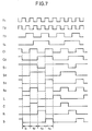
- Fig. 7 is a timing chart for illustrating the operation of the test tone circuit shown in Fig. 6.
- Embodiments of the present invention are now described in detail with reference to the accompanying drawings.
- Fig. 2 is a block diagram schematically showing the structure of a principal part of a television receiver according to an embodiment of the present invention. Referring to Fig. 2,
input terminals - A
surround decoder 3 contains a directivity enhancing circuit which receives the sound signals L' and R' and decodes the same through the Pro-Logic surround system to output the left channel signal L, the right channel signal R, the center channel signal C and the surround channel signal S. Avolume control circuit 4 controls levels of the signals outputted from thesurround decoder 3 respectively. Anaudio output circuit 5 amplifies the signals controlled by thevolume control circuit 4. Aleft channel speaker 6 is arranged on a front left position to receive the left channel signal L. A right channel speaker 7 is arranged on a front right position to receive the right channel signal R. Acenter channel speaker 8 is arranged on a front center position to receive the center channel signalC. Surround speakers - A
test tone circuit 11 supplies a test tone to thesurround decoder 3 in place of the sound signals from theinput terminals function part 12 of a remote control transmitter selects a test mode. Thetest tone circuit 11 includes atest tone generator 110, afirst transfer switch 111, asecond transfer switch 112, aninverter 113 and atimer circuit 114. - The
test tone generator 110 generates a test tone of 500 Hz. Thefirst transfer switch 11 has terminals d0 and d3, to which the test tone is supplied. Thesecond transfer switch 112 has terminals d1, d2 and d3, to which the test tone is supplied. Theinverter 113 inverts the output from thesecond transfer switch 112. The output of theinverter 113 is supplied to a terminal d1 of thefirst transfer switch 111. Outputs of thefirst transfer switch 111 and theinverter 113 are supplied to athird transfer switch 13. Thetimer circuit 114 generates a switching signal for sequentially switching the respective ones of the first andsecond transfer switches - The
third transfer switch 13 selects the sound signals from theinput terminals test tone circuit 11, and supplies the same to thesurround decoder 3. Amicrocomputer 14 receives an operation command signal from thefunction part 12 and the switching signal from thetimer circuit 114, and supplies a volume control signal to thevolume control circuit 4. A colorconversion control circuit 15 is controlled by a color conversion control signal from themicrocomputer 14. Acharacter display circuit 16 is controlled by a color conversion signal outputted from the colorconversion control circuit 15. ACRT 17 displays the character display output from thecharacter display circuit 16 on its screen. - Test mode operation of the circuit shown in Fig. 2 is now described with reference to a flow chart shown in Fig. 3.
- First, a test mode switch provided in the
function part 12 is operated so that the operation command signal is supplied to themicrocomputer 14. Thus, the circuit shown in Fig. 2 is set in the test mode (steps S1 and S2 of Fig. 3). In other words, themicrocomputer 14 controls thecharacter display circuit 16, and theCRT 17 displays characters shown in Fig. 4 on its screen. - At the same time, the
third transfer switch 13 is switched to connect input terminals ℓ and r of thesurround decoder 3 to thetest tone circuit 11. In thetest tone circuit 11, thetest tone generator 110 generates the test tone, and thetimer circuit 114 generates the switching signal. In response to the switching signal, the respective ones of the first and second transfer switches 111 and 112 are sequentially switched toward the terminals d0 to d3 in the prescribed cycle (1.5 sec.). - That is, when the first and second transfer switches 111 and 112 are set at the terminals d0, the test tone appears only at an
output terminal 01 of thefirst transfer switch 111, so that the same is supplied to the input terminal ℓ of thesurround decoder 3. Thus, only a left output terminal ℓ1 of thesurround decoder 3 outputs a demodulated test tone, thereby to drive only theleft channel speaker 6. - When the first and second transfer switches 111 and 112 are set at the terminals d1, in-phase test tones are inputted in the input terminals ℓ and r of the
surround decoder 3. Thus, only a center output terminal c1 of thesurround decoder 3 outputs a demodulated test tone, thereby to drive only thecenter channel speaker 8. - When the first and second transfer switches 111 and 112 are set at the terminals d2, the test tone is inputted only in the input terminal r of the
surround decoder 3. Thus, only a right output terminal r1 of thesurround decoder 3 outputs a demodulated test tone, thereby to drive only the right channel speaker 7. - When the first and second transfer switches 111 and 112 are set at the terminals d3, opposite-phase test tones are inputted in the input terminals ℓ and r of the
surround decoder 3. Thus, only a surround output terminal s1 of thesurround decoder 3 outputs a demodulated test tone, thereby to drive only thesurround channel speakers - The speakers are sequentially switched and driven every 1.5 sec. in the aforementioned manner.
- On the other hand, the switching signal outputted from the
timer circuit 114 is also supplied to themicrocomputer 14. Thus, themicrocomputer 14 decides which speaker currently outputs the test tone (step S3), and supplies the color conversion control signal to the colorconversion control circuit 15 in accordance with the result of the decision to control the same, while controlling thecharacter display circuit 16 in accordance with the color conversion signal outputted from the colorconversion control circuit 15. When theleft channel speaker 6 currently outputs the test tone, for example, the characters "FRONT" and the balance symbol "L" are displayed in a color which is different from that of other characters shown in Fig. 4 (step S4). - Therefore, the user can recognize that the
left channel speaker 6 is currently driven. Thus, the user can control the sound volume of theleft channel speaker 6 by operating a volume control key provided in the function part 12 (steps S5 and S6). Referring to Fig. 4 showing screen display, the volume levels of the respective speakers are expressed by the numbers of thick vertical bars. - When a decision is made that the circuit is not set in the Dolby Pro-Logic surround mode at the step S1 of Fig. 3 or that the circuit is not set in the test mode at the step S2, other control operation is performed to switch the channel, turn on/off power, switch a television/video mode, control the volume, switch the surround mode or the like.
- Fig. 5 shows another example of on-screen volume display. In the example shown in Fig. 5, volume levels of the respective speakers are displayed on five positions of the screen in correspondence to actual speaker positions.
- In the aforementioned embodiment, the characters showing the speaker currently outputting the test tone are displayed in a color different from that of the characters corresponding to the remaining speakers. Alternatively, the characters corresponding to the speaker currently outputting the test tone may be changed in brightness or flashed, for example. The point is that the speaker currently outputting the test tone can be identified by changing the mode of display corresponding to the speaker.
- With reference to Figs. 6 and 7, another embodiment of the present invention is now described. In this embodiment, a test tone circuit is integrated into an IC.
- Referring to Fig. 6, an integrated
test tone circuit 18 is enclosed by two-dot chain lines. Thetest tone circuit 18 includes atimer circuit 19, afirst decoder 20, atest tone generator 21, afirst switching circuit 22, asecond switching circuit 23, a third switching circuit 24, afourth switching circuit 25 and asecond decoder 26. - The
timer circuit 19 includes anoscillator 190 of 30 KHz, afrequency divider 191 which divides the output of theoscillator 190 by 24576 to generate a signal of 1.22 Hz, T-flip-flops flops inverter 196. Thefirst decoder 20 includes eight ANDgates 200 to 207 and three ORgates 208 to 210. Thefirst decoder 20 decodes timing signals C1 and C2 outputted from thetimer circuit 19, to output control signals S1 to S4. - The
first switching circuit 22 is controlled by the control signal S4. Thisfirst switching circuit 22 directly outputs a test tone received from thetest tone generator 21 when a left or right channel speaker is driven, while attenuating the test tone by -3 dB in anamplifier 220 and outputting the same when a center or surround channel speaker is driven. - The second and
third switching circuits 23 and 24 include buffer amplifiers and switches respectively. The second andthird switching circuits 23 and 24 are controlled by the control signals S1 and S2 respectively. Thefourth switching circuit 25 includes an inverter and a switch, and is controlled by the control signal S3. The output of thesecond switching circuit 23 is inputted in an input terminal ℓ of asurround decoder 3 through athird transfer switch 13, while outputs of the third andfourth switching circuits 24 and 25 are coupled with each other and inputted in another input terminal r of thesurround decoder 3 through thethird transfer switch 13. - The
second decoder 26 includes ANDgates 260 to 263. Thissecond decoder 26 decodes the timing signals C1 and C2 outputted from thetimer circuit 19, to sequentially derive high outputs at output terminals TL, TC, TR and TS. - The operation of the circuit shown in Fig. 6 is now described with reference to the timing chart shown in Fig. 7.
- The
first decoder 20 decodes the timing signals C1 and C2 outputted from thetimer circuit 19, to obtain the control signals S1 to S4. - In a period t1, the
first switching circuit 22 is switched toward contacts a and a in response to the control signal S4. Thus, the test tone is directly supplied to the first tofourth switching circuits 23 to 25. In response to the control signals S1 to S3, thesecond switching circuit 23 is closed and the third andfourth switching circuits 24 and 25 are opened. Thus, the test tone is outputted only at an output terminal ℓ0. - Then, in a period t2, the
first switching circuit 22 is switched toward contacts b and b. Thus, the test tone is attenuated by -3 dB. The second andthird switching circuits 23 and 24 are closed and thefourth switching circuit 25 is opened. Thus, in-phase test tones are outputted at the output terminals ℓ0 and r0. - Then, in a period t3, the
first switching circuit 22 is again switched toward the contacts a and a. Thus, the test tone is outputted with no attenuation. Thesecond switching circuit 23 is opened and the third switching circuit 24 is closed, while thefourth switching circuit 25 is opened. Thus, the test tone is outputted only at the output terminal r0. - Then, in a period t4, the
first switching circuit 22 is again switched toward the contacts b and b. Thus, the test tone is attenuated by -3 dB. Thesecond switching circuit 23 is closed and the third switching circuit 24 is opened, while thefourth switching circuit 25 is closed. Thus, opposite-phase test tones are outputted at the output terminals ℓ0 and r0. - On the other hand, the timing signals C1 and C2 outputted from the
timer circuit 19 are also supplied to thesecond decoder 26. Thus, high outputs are derived at the output terminals TL, TC, TR and TS in the periods t1, t2, t3 and t4 respectively. The outputs are supplied to themicrocomputer 14, so that themicrocomputer 14 can decide which speaker currently outputs the test tone. - According to this embodiment, as hereinabove described, a CRT displays which speaker currently outputs the test tone by changing the display mode when the user controls the volume levels of the respective speakers in a surround test mode. Thus, the user can confirm the currently driven speaker and its volume at a glance, to extremely easily control the sound volume. Further, erroneous connection of the speaker can be easily confirmed.
- Although the present invention has been described and illustrated in detail, it is clearly understood that the same is by way of illustration and example only and is not to be taken by way of limitation, the spirit and scope of the present invention being limited only by the terms of the appended claims.
Claims (3)
- A television receiver having a television screen (17) and reproducing sound signals corresponding to a plurality of channels, comprising:
volume control means (14) for controlling levels of said sound signals corresponding to said plurality of channels respectively;
a plurality of speaker means (6 to 10) provided in correspondence to said plurality of channels for regenerating said sound signals controlled by said volume control means (4) respectively;
test tone supply means (11; 18) for supplying a test tone of a prescribed frequency to said plurality of speaker means (6 to 10) through said volume control means (4) every prescribed period; and
display means (14 to 16) for displaying which speaker means is currently supplied with said test tone on said television screen (17). - A television receiver in accordance with claim 1, wherein
said display means (14 to 16) further display volume levels corresponding to said plurality of channels on said television screen (17). - A television receiver in accordance with claim 2, wherein
said plurality of channels include first, second, third and fourth channels,
said test tone supply means (11; 18) includes:
test tone generating means (110; 21) for generating a test tone of a prescribed frequency,
control signal generating means (114; 19, 20, 26) for generating a control signal in a prescribed cycle, and
switching means (111 to 113, 22 to 25) for supplying said test tone to said plurality of speaker means (6 to 10) through said volume control means (4) every prescribed period in response to said control signal, and
said display means includes control means (14 to 16) making display indicating the speaker currently supplied with said test tone on said television screen (17) in response to said control signal from said control signal generating means (114; 19, 20, 26).
Applications Claiming Priority (7)
| Application Number | Priority Date | Filing Date | Title |
|---|---|---|---|
| JP180512/88 | 1988-07-20 | ||
| JP18051288 | 1988-07-20 | ||
| JP9602188 | 1988-07-20 | ||
| JP96021/88 | 1988-07-20 | ||
| JP151984/89 | 1989-06-13 | ||
| JP1151984A JPH02131700A (en) | 1988-07-20 | 1989-06-13 | Television receiver |
| EP89113282A EP0352627B1 (en) | 1988-07-20 | 1989-07-19 | Sound reproducer |
Related Parent Applications (2)
| Application Number | Title | Priority Date | Filing Date |
|---|---|---|---|
| EP89113282A Division EP0352627B1 (en) | 1988-07-20 | 1989-07-19 | Sound reproducer |
| EP89113282.1 Division | 1989-07-19 |
Publications (2)
| Publication Number | Publication Date |
|---|---|
| EP0516183A1 true EP0516183A1 (en) | 1992-12-02 |
| EP0516183B1 EP0516183B1 (en) | 1996-04-10 |
Family
ID=26437225
Family Applications (1)
| Application Number | Title | Priority Date | Filing Date |
|---|---|---|---|
| EP92112188A Expired - Lifetime EP0516183B1 (en) | 1988-07-20 | 1989-07-19 | Television receiver |
Country Status (2)
| Country | Link |
|---|---|
| EP (1) | EP0516183B1 (en) |
| KR (1) | KR960013305B1 (en) |
Cited By (3)
| Publication number | Priority date | Publication date | Assignee | Title |
|---|---|---|---|---|
| GB2294854A (en) * | 1994-11-03 | 1996-05-08 | Solid State Logic Ltd | Audio signal processing |
| US5636283A (en) * | 1993-04-16 | 1997-06-03 | Solid State Logic Limited | Processing audio signals |
| WO1999011100A1 (en) * | 1997-08-26 | 1999-03-04 | Koninklijke Philips Electronics N.V. | Method for controlling signal parameters |
Families Citing this family (1)
| Publication number | Priority date | Publication date | Assignee | Title |
|---|---|---|---|---|
| CN108769877A (en) * | 2018-05-31 | 2018-11-06 | 北京橙鑫数据科技有限公司 | Volume equalization methods, device and electronic equipment |
Citations (2)
| Publication number | Priority date | Publication date | Assignee | Title |
|---|---|---|---|---|
| GB2118407A (en) * | 1982-03-31 | 1983-10-26 | Thorn Emi Ferguson | Television receiver |
| US4577188A (en) * | 1981-09-03 | 1986-03-18 | Victor Company Of Japan, Ltd. | Level display device for audio signal |
-
1989
- 1989-07-19 KR KR1019890010268A patent/KR960013305B1/en not_active IP Right Cessation
- 1989-07-19 EP EP92112188A patent/EP0516183B1/en not_active Expired - Lifetime
Patent Citations (2)
| Publication number | Priority date | Publication date | Assignee | Title |
|---|---|---|---|---|
| US4577188A (en) * | 1981-09-03 | 1986-03-18 | Victor Company Of Japan, Ltd. | Level display device for audio signal |
| GB2118407A (en) * | 1982-03-31 | 1983-10-26 | Thorn Emi Ferguson | Television receiver |
Cited By (5)
| Publication number | Priority date | Publication date | Assignee | Title |
|---|---|---|---|---|
| US5636283A (en) * | 1993-04-16 | 1997-06-03 | Solid State Logic Limited | Processing audio signals |
| GB2294854A (en) * | 1994-11-03 | 1996-05-08 | Solid State Logic Ltd | Audio signal processing |
| US5715318A (en) * | 1994-11-03 | 1998-02-03 | Hill; Philip Nicholas Cuthbertson | Audio signal processing |
| GB2294854B (en) * | 1994-11-03 | 1999-06-30 | Solid State Logic Ltd | Audio signal processing |
| WO1999011100A1 (en) * | 1997-08-26 | 1999-03-04 | Koninklijke Philips Electronics N.V. | Method for controlling signal parameters |
Also Published As
| Publication number | Publication date |
|---|---|
| KR960013305B1 (en) | 1996-10-02 |
| EP0516183B1 (en) | 1996-04-10 |
| KR910004035A (en) | 1991-02-28 |
Similar Documents
| Publication | Publication Date | Title |
|---|---|---|
| EP0352627B1 (en) | Sound reproducer | |
| US5237418A (en) | Audio output circuit in electronic apparatus with composite display function | |
| US7668317B2 (en) | Audio post processing in DVD, DTV and other audio visual products | |
| KR100682490B1 (en) | Audio signal processor and audio device | |
| JPH03270600A (en) | Audio reproducing device | |
| US6681019B1 (en) | Polarity determining circuit for loudspeakers, an audio circuit having a function of determining polarities of loudspeakers, and an audio circuit having functions of determining polarities of loudspeakers and switching the polarities | |
| US5197099A (en) | Multiple-channel audio reproduction apparatus | |
| US5261005A (en) | Sound field control device | |
| CN101276588B (en) | Method for outputting audio signals and audio decoder | |
| EP0516183B1 (en) | Television receiver | |
| US5987141A (en) | Stereo expander | |
| EP1750476A2 (en) | Audio apparatus and control method | |
| JPH02131700A (en) | Television receiver | |
| US7502477B1 (en) | Audio reproducing apparatus | |
| US5123051A (en) | Sound field reproducing apparatus | |
| JPH03258176A (en) | Television receiver | |
| KR20000002810U (en) | Automatic Sound Mode Selector of Stereo Sound Equipment | |
| KR100276448B1 (en) | Q stereo sound enhancement method | |
| EP1471771A2 (en) | Audio reproduction apparatus and video receiving apparatus | |
| KR200206053Y1 (en) | An apparatus for displaying output level of audio signal in an audio system | |
| JP2000125400A (en) | Audiovisual device | |
| CA1321756C (en) | Sound field reproducing apparatus | |
| JP2528993B2 (en) | Frequency characteristic control device | |
| JP2600035Y2 (en) | Audio amplifier power display | |
| JP2001128283A (en) | Loudspeaker output switching control method and controller therefor |
Legal Events
| Date | Code | Title | Description |
|---|---|---|---|
| PUAI | Public reference made under article 153(3) epc to a published international application that has entered the european phase |
Free format text: ORIGINAL CODE: 0009012 |
|
| AC | Divisional application: reference to earlier application |
Ref document number: 352627 Country of ref document: EP |
|
| AK | Designated contracting states |
Kind code of ref document: A1 Designated state(s): DE FR GB |
|
| RIN1 | Information on inventor provided before grant (corrected) |
Inventor name: OGAWA, RYUICHI Inventor name: TOSAKA, FUMIO Inventor name: OKADA, HIROFUMI Inventor name: TANNO, MASAYA Inventor name: IMAIDA, TAKAYUKI Inventor name: ISHIKAWA, TSUTOMU |
|
| 17P | Request for examination filed |
Effective date: 19921222 |
|
| 17Q | First examination report despatched |
Effective date: 19950821 |
|
| GRAH | Despatch of communication of intention to grant a patent |
Free format text: ORIGINAL CODE: EPIDOS IGRA |
|
| GRAA | (expected) grant |
Free format text: ORIGINAL CODE: 0009210 |
|
| AC | Divisional application: reference to earlier application |
Ref document number: 352627 Country of ref document: EP |
|
| AK | Designated contracting states |
Kind code of ref document: B1 Designated state(s): DE FR GB |
|
| REF | Corresponds to: |
Ref document number: 68926249 Country of ref document: DE Date of ref document: 19960515 |
|
| ET | Fr: translation filed | ||
| PLBE | No opposition filed within time limit |
Free format text: ORIGINAL CODE: 0009261 |
|
| STAA | Information on the status of an ep patent application or granted ep patent |
Free format text: STATUS: NO OPPOSITION FILED WITHIN TIME LIMIT |
|
| 26N | No opposition filed | ||
| REG | Reference to a national code |
Ref country code: GB Ref legal event code: IF02 |
|
| PGFP | Annual fee paid to national office [announced via postgrant information from national office to epo] |
Ref country code: DE Payment date: 20070712 Year of fee payment: 19 |
|
| PGFP | Annual fee paid to national office [announced via postgrant information from national office to epo] |
Ref country code: GB Payment date: 20070718 Year of fee payment: 19 |
|
| PGFP | Annual fee paid to national office [announced via postgrant information from national office to epo] |
Ref country code: FR Payment date: 20070710 Year of fee payment: 19 |
|
| GBPC | Gb: european patent ceased through non-payment of renewal fee |
Effective date: 20080719 |
|
| PG25 | Lapsed in a contracting state [announced via postgrant information from national office to epo] |
Ref country code: DE Free format text: LAPSE BECAUSE OF NON-PAYMENT OF DUE FEES Effective date: 20090203 |
|
| REG | Reference to a national code |
Ref country code: FR Ref legal event code: ST Effective date: 20090331 |
|
| PG25 | Lapsed in a contracting state [announced via postgrant information from national office to epo] |
Ref country code: GB Free format text: LAPSE BECAUSE OF NON-PAYMENT OF DUE FEES Effective date: 20080719 |
|
| PG25 | Lapsed in a contracting state [announced via postgrant information from national office to epo] |
Ref country code: FR Free format text: LAPSE BECAUSE OF NON-PAYMENT OF DUE FEES Effective date: 20080731 |