EP0515822B1 - Anti-lock/traction modulator for brake control system - Google Patents
Anti-lock/traction modulator for brake control system Download PDFInfo
- Publication number
- EP0515822B1 EP0515822B1 EP92106535A EP92106535A EP0515822B1 EP 0515822 B1 EP0515822 B1 EP 0515822B1 EP 92106535 A EP92106535 A EP 92106535A EP 92106535 A EP92106535 A EP 92106535A EP 0515822 B1 EP0515822 B1 EP 0515822B1
- Authority
- EP
- European Patent Office
- Prior art keywords
- brake
- fluid
- pump
- valve
- accumulator
- Prior art date
- Legal status (The legal status is an assumption and is not a legal conclusion. Google has not performed a legal analysis and makes no representation as to the accuracy of the status listed.)
- Expired - Lifetime
Links
Images
Classifications
-
- B—PERFORMING OPERATIONS; TRANSPORTING
- B60—VEHICLES IN GENERAL
- B60T—VEHICLE BRAKE CONTROL SYSTEMS OR PARTS THEREOF; BRAKE CONTROL SYSTEMS OR PARTS THEREOF, IN GENERAL; ARRANGEMENT OF BRAKING ELEMENTS ON VEHICLES IN GENERAL; PORTABLE DEVICES FOR PREVENTING UNWANTED MOVEMENT OF VEHICLES; VEHICLE MODIFICATIONS TO FACILITATE COOLING OF BRAKES
- B60T8/00—Arrangements for adjusting wheel-braking force to meet varying vehicular or ground-surface conditions, e.g. limiting or varying distribution of braking force
- B60T8/32—Arrangements for adjusting wheel-braking force to meet varying vehicular or ground-surface conditions, e.g. limiting or varying distribution of braking force responsive to a speed condition, e.g. acceleration or deceleration
- B60T8/34—Arrangements for adjusting wheel-braking force to meet varying vehicular or ground-surface conditions, e.g. limiting or varying distribution of braking force responsive to a speed condition, e.g. acceleration or deceleration having a fluid pressure regulator responsive to a speed condition
- B60T8/48—Arrangements for adjusting wheel-braking force to meet varying vehicular or ground-surface conditions, e.g. limiting or varying distribution of braking force responsive to a speed condition, e.g. acceleration or deceleration having a fluid pressure regulator responsive to a speed condition connecting the brake actuator to an alternative or additional source of fluid pressure, e.g. traction control systems
- B60T8/4809—Traction control, stability control, using both the wheel brakes and other automatic braking systems
- B60T8/4827—Traction control, stability control, using both the wheel brakes and other automatic braking systems in hydraulic brake systems
- B60T8/489—Traction control, stability control, using both the wheel brakes and other automatic braking systems in hydraulic brake systems using separate traction control modulators
-
- B—PERFORMING OPERATIONS; TRANSPORTING
- B60—VEHICLES IN GENERAL
- B60T—VEHICLE BRAKE CONTROL SYSTEMS OR PARTS THEREOF; BRAKE CONTROL SYSTEMS OR PARTS THEREOF, IN GENERAL; ARRANGEMENT OF BRAKING ELEMENTS ON VEHICLES IN GENERAL; PORTABLE DEVICES FOR PREVENTING UNWANTED MOVEMENT OF VEHICLES; VEHICLE MODIFICATIONS TO FACILITATE COOLING OF BRAKES
- B60T8/00—Arrangements for adjusting wheel-braking force to meet varying vehicular or ground-surface conditions, e.g. limiting or varying distribution of braking force
- B60T8/32—Arrangements for adjusting wheel-braking force to meet varying vehicular or ground-surface conditions, e.g. limiting or varying distribution of braking force responsive to a speed condition, e.g. acceleration or deceleration
- B60T8/34—Arrangements for adjusting wheel-braking force to meet varying vehicular or ground-surface conditions, e.g. limiting or varying distribution of braking force responsive to a speed condition, e.g. acceleration or deceleration having a fluid pressure regulator responsive to a speed condition
- B60T8/40—Arrangements for adjusting wheel-braking force to meet varying vehicular or ground-surface conditions, e.g. limiting or varying distribution of braking force responsive to a speed condition, e.g. acceleration or deceleration having a fluid pressure regulator responsive to a speed condition comprising an additional fluid circuit including fluid pressurising means for modifying the pressure of the braking fluid, e.g. including wheel driven pumps for detecting a speed condition, or pumps which are controlled by means independent of the braking system
- B60T8/4013—Fluid pressurising means for more than one fluid circuit, e.g. separate pump units used for hydraulic booster and anti-lock braking
-
- B—PERFORMING OPERATIONS; TRANSPORTING
- B60—VEHICLES IN GENERAL
- B60T—VEHICLE BRAKE CONTROL SYSTEMS OR PARTS THEREOF; BRAKE CONTROL SYSTEMS OR PARTS THEREOF, IN GENERAL; ARRANGEMENT OF BRAKING ELEMENTS ON VEHICLES IN GENERAL; PORTABLE DEVICES FOR PREVENTING UNWANTED MOVEMENT OF VEHICLES; VEHICLE MODIFICATIONS TO FACILITATE COOLING OF BRAKES
- B60T8/00—Arrangements for adjusting wheel-braking force to meet varying vehicular or ground-surface conditions, e.g. limiting or varying distribution of braking force
- B60T8/32—Arrangements for adjusting wheel-braking force to meet varying vehicular or ground-surface conditions, e.g. limiting or varying distribution of braking force responsive to a speed condition, e.g. acceleration or deceleration
- B60T8/34—Arrangements for adjusting wheel-braking force to meet varying vehicular or ground-surface conditions, e.g. limiting or varying distribution of braking force responsive to a speed condition, e.g. acceleration or deceleration having a fluid pressure regulator responsive to a speed condition
- B60T8/42—Arrangements for adjusting wheel-braking force to meet varying vehicular or ground-surface conditions, e.g. limiting or varying distribution of braking force responsive to a speed condition, e.g. acceleration or deceleration having a fluid pressure regulator responsive to a speed condition having expanding chambers for controlling pressure, i.e. closed systems
- B60T8/4275—Pump-back systems
Definitions
- the present invention relates to an antilock/traction modulator according to the preamble of claim 1, and more specifically to a brake control system for use in a vehicle which applies an appropriate brake force to vehicle wheels to prevent the wheels from slipping when the vehicle starts to move rapidly, and controls the brake force appropriately to prevent the vehicle wheels from skidding when the vehicle brakes.
- an anti-lock/traction modulator having functions of an anti-lock control for preventing vehicle wheels from skidding when the vehicle brakes and a traction control for preventing the wheels from excessive slipping when the vehicle starts to move or accelerates rapidly, for a driver to drive a vehicle easily and improve abilities of start, acceleration and driving stability of the vehicle.
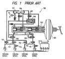
- Fig. 1 is a schematic view of another brake apparatus described in US-A 4,750,788 wherein a brake apparatus 100 is provided with a master cylinder 102, booster 103, hydraulic pump P, adjusting valve 106, change valves 104, 105 and 108-115, brake cylinders of driving and driven wheels, reservoir tank 107 and oil passages for selectively communicating these devices and valves.
- a brake apparatus 100 is provided with a master cylinder 102, booster 103, hydraulic pump P, adjusting valve 106, change valves 104, 105 and 108-115, brake cylinders of driving and driven wheels, reservoir tank 107 and oil passages for selectively communicating these devices and valves.
- the condition of the change valves during the normal braking operation is as shown in Fig. 1.
- a hydraulic pressure is generated in the master cylinder 102 by depressing a brake pedal
- the hydraulic (brake) pressure is supplied to a brake cylinder for each of the vehicle wheels from outlet ports I, II of the cylinder 102 through the change valves 108, 111, 109 and 113.
- the change valves 104, 108 and 109 are changed from their condition shown in Fig. 1 and, at the same time, the hydraulic pump P is actuated.
- the brake pressure generated by the hydraulic pump P becomes equal in pressure to the hydraulic pressure generated by the master cylinder 102 owing to the operation of the adjusting valve 106 to which the hydraulic pressure from the master cylinder 102 is applied. Accordingly, the brake pressure generated by the hydraulic pump P becomes ready for being supplied to the wheel cylinders through the valves 108 and 109.
- the valves 110 and 111, or 112 and 113 are controlled to open and close to control the brake force to hold, release and apply according to the condition of skid of each of the vehicle wheels, thereby achieving the anti-skid control.
- valves 104, 105 108, 109, 114 and 115 are changed from the condition shown in Fig. 1 and, at the same time, the hydraulic pump P is actuated.
- the brake pressure generated by the hydraulic pump P of an in-line type is supplied to the brake cylinders through valves 108 and 109 to thereby apply the brake force to the vehicle wheels.
- the valves 110 and 111 or 112 and 113 are controlled to open and close to control the brake force to hold, release and apply according to the condition of the slip of each of the driving wheels, thereby achieving the traction control.
- valves 104, 105 and 108-115 as well as the hydraulic pump P are controlled by a publicly known electronic control device (now shown) in accordance with output signals of wheel speed sensors for detecting the condition of the vehicle wheels (skidding or slipping).
- the skid or slip of the vehicle wheels are appropriately controlled and, therefore, the vehicle can decelerate or stop stably and start to move smoothly.
- the conventional anti-lock/traction modulator as described above has a disadvantage that if a part of the hydraulic pressure passage circuit for the traction control comes to fail or have a damage the passage circuit for the normal brake operation comes also to deteriorate which raises a serious problem in safety driving since the pressure passage circuit for the traction control communicates with that for the anti-skid control.
- the TCS pump of an in-line type is required to pump up the brake fluid against the passage resistance generated between the master cylinder and the modulator, thereby lowering the ability of the pump.
- the present invention was made in view of the foregoing difficulties and problems accompanying the conventional anti-lock/traction modulator.
- the object of the invention is to provide an anti-lock/traction modulator capable of improving a safety driving by which a normal brake operation and an anti-skid control operation can stably be operated even if a failure or damage is occurred on a passage circuit for a traction control.
- an anti-lock/traction modulator wherein the pressure source is arranged in an anti-slip pressure circuit which is hydraulically separate from the brake circuit while said pressure source comprises a fluid accumulator and a pump which is worked when slip occurs and said pump arranged between the fluid accumulator and the compression piston urges the compression piston.
- an anti-lock/traction modulator including a hydraulic pressure passage circuit for an anti-skid control (brake circuit) and a hydraulic pressure source circuit for a traction control (anti-slip pressure circuit) in which an accumulator disposed at an inlet side of a pump for accumulating a predetermined pressure, and which circuit supplies a brake pressure to the hydraulic circuit for anti-skid control merely during the traction control operation.
- These circuits are connected to each other through a piston so that brake pressure is supplied to brake cylinders of vehicle wheels from the piston during the traction control operation.
- a cut valve is actuated to shut a fluid communication between a master cylinder and a hold valve and also a change valve is actuated to shut a fluid communication between a compression piston and an accumulator.
- a TCS pump starts to pump-up brake fluid from the accumulator.
- the brake fluid thus pumped-up is supplied to a compression piston chamber to urge a compression piston to move against an elastic force of a compression spring.
- the brake fluid contained in the compression piston is supplied to the brake cylinders through the hold valve, so that the driving wheels brake and the undesired slip is suppressed.
- a pump for anti-skid control, hold valve and decay valve are controlled by the electronic control device to control the brake force to hold, release and apply according to the slipping condition of each of the driving wheels.
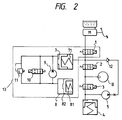
- Fig. 2 is a schematic view showing one example of an anti-lock/traction modulator of the present invention applied to a fluid pressure passage circuit for one of driving wheels of a vehicle. Another modulator having the same function is applied to the other driving wheels. Every valves disposed in the modulator are controlled by a known electronic control device (not shown).
- a master cylinder M, cut valve 1, hold valve 2, decay valve 3 and reservoir 4 are connected in series to each other for each of the driving wheels of the vehicle.
- a wheel cylinder of a brake B for the driving wheel is connected to a fluid passage connecting between the hold valve 2 and decay valve 3.
- a brake circuit pump 5 for anti-skid control is provided with an inlet port connected between the decay valve 3 and reservoir 4 and an outlet port connected to a fluid passage between the cut valve 1 and hold valve 2 through a non-return valve 12.
- a compression piston 7 constituting a TCS unit 13 described hereinafter is connected also to the passage between the cut valve 1 and hold valve 2.
- the TCS unit 13 is constituted by the compression piston 7, a relief valve 11, accumulator 8, a TCS pump 9 and a change valve 10.
- the compression piston 7, TCS pump 9 and accumulator 8 are connected in series to each other, whereas the TCS pump 9, change valve 10 and the relief valve 11 are connected in parallel with each other.
- the compression piston 7 is provided with a cylinder chamber divided into two chambers and supplies brake fluid to the fluid pressure passage circuit for anti-skid control by an operation of the fluid pressure generated by the TCS pump 9 during the traction control operation.
- One chamber of the compression piston 7 connects to an outlet port of the TCS pump through a fluid passage while the other chamber of which connects to the passage between the cut valve 1 and hold valve 2 of the fluid pressure passage circuit for anti-skid control.
- a compression spring 71 is disposed in the other chamber of the compression piston 7 to always urge the compression piston 7 leftwardly of Fig. 2.
- the accumulator 8 is provided with a piston 82 and an accumulator spring 81 disposed therein for urging the piston 82 leftwardly of Fig. 2, and accumulates the brake fluid contained in the compression piston 7 not during the traction control operation.
- the compression spring 71 of the compression piston 7 has a spring stiffness which is larger than that of the accumulator spring 81 of the accumulator 8. Accordingly, not during the traction control operation, the compression piston 7 is urged toward leftside of Fig. 2 by an elastic force of the compression spring 71 whereas the accumulator piston 82 is urged toward rightside of Fig. 2 against an elastic force of the spring 81 by the brake fluid pressure applied by the compression piston 7. In this condition, one chamber of the compression piston 7 at the accumulator side on the other hand communicates with the fluid passage circuit for anti-skid control, and the chamber is filled with brake fluid.
- the TCS pump 9 generates a fluid pressure by changing the change valve 10 to close during the traction control operation.
- the TCS pump 9 is actuated in association with the brake circuit pump 5 for anti-skid control so that the brake fluid flows circulatedly from the accumulator 8 through TCS pump 9 and change valve 10 and back to the accumulator 8 by holding the change valve 10 to open. Accordingly, no pressure increase of the fluid is occurred in this condition.
- the condition of the valves is as shown in Fig. 2.
- the master cylinder M generates a fluid (brake) pressure when a brake pedal is depressed.
- the brake pressure generated by the master cylinder M is supplied from the outlet port thereof to the brake cylinder of a brake B for the vehicle wheel through the cut valve 1, hold valve 2, so that the brake operation is obtained.
- the master cylinder M produces a hydraulic pressure when the brake pedal is depressed to brake the vehicle.
- the brake pressure generated by the master cylinder M is supplied from the outlet port thereof to the brake cylinder of the brake B for the wheel through the cut valve 1, hold valve 2, so that the brake operation is actuated.
- an electronic control circuit controls the hold valve 2, decay valve 3 and brake circuit pump 5 for anti-skid control in accordance with the condition of the skid of the wheel. Supposing now the electronic control device outputs a signal representing "a brake-hold control', the hold valve 2 is closed to shut a fluid communication between the master cylinder M and the wheel cylinder to hold the brake pressure applied to the wheel cylinder.
- the hold valve 2 is closed to shut the fluid communication between the master cylinder M and the wheel cylinder and, at the same time, the decay valve 3 opens to allow the brake fluid in the wheel cylinder to discharge into the reservoir 4 through a passage connecting between the wheel cylinder and the reservoir 4 to thereby release the brake force.
- the brake fluid supplied to the reservoir 4 is circulated back to the master cylinder M by the brake circuit pump 5 for anti-skid control which is actuated at the same time when the fluid pressure control is operated.
- the fluid pressure control as described above is carried out independently in each of the wheel cylinders of the vehicle.
- the electronic control device controls the hold valve 2, decay valve 3 and the brake circuit pump 5 for anti-skid control in accordance with the condition of the slip of the vehicle wheels. Supposing now the electronic control device outputs a control signal representing a slip of driving wheel, the cut valve 1 closes to shut a fluid communication between the master cylinder M and the hold valve 2 and at the same time the change valve 10 closes to shut a fluid communication between the compression piston 7 and the accumulator 8. Further, the TCS pump 9 starts to pump-up the brake fluid from the accumulator 8.
- the brake fluid pumped up by the TCS pump 9 is supplied to the compression piston chamber of the compression piston 7 to urge the compression piston 7 rightwardly of Fig. 2 against the elastic force of the compression spring 71.
- the rightward movement of the compression piston 7 causes the brake fluid in the compression piston 7 to supply into the wheel cylinder of the brake B through the hold valve 2, so that the driving wheel brakes to thereby suppress the driving slippage.
- the fluid pressure pump 5 for anti-skid control, hold valve 2 and the decay valve 3 are also controlled by the electronic control device to control the brake force to hold, release and apply in accordance with the condition of the slip of the driving wheel.
- the hold valve 2 and the decay valve 3 are controlled to close to hold the brake force (brake circuit pump 5 for anti-skid is not actuated).
- the decay valve 3 is controlled to open to allow the brake fluid in the brake cylinder to discharge into the reservoir 4 and, at the same time, the fluid pressure pump 5 for anti-skid starts to pump-up the brake fluid.
- the brake fluid discharged from the brake circuit pump 5 for anti-skid control is circulated to flow into the compression piston 7.
- the compression piston 7 is urged to move leftwardly in Fig. 2 so that the brake fluid in the compression piston is flown in the accumulator 8 through the relief valve 11.
- the brake pressure applied to the brake cylinder decreases to release the brake force.
- the TCS pump 9 is still actuated, however, the brake fluid supplied from the TCS pump 9 is circulated through the relief valve 11.
- the driving slippage is appropriately controlled.
- the electronic control device detects such a condition and controls the TCS pump 9 to stop and the cut valve 1 to be in a condition shown in Fig. 2.
- the fluid pressure passage circuit for anti-skid control and the fluid pressure circuit for traction control are systemized independently, the normal brake control and the anti-skid control operations can stably be operated even if a failure or damage is occurred on the fluid passage circuit for the traction control.
Landscapes
- Physics & Mathematics (AREA)
- Fluid Mechanics (AREA)
- Engineering & Computer Science (AREA)
- Transportation (AREA)
- Mechanical Engineering (AREA)
- Regulating Braking Force (AREA)
Description
- The present invention relates to an antilock/traction modulator according to the preamble of claim 1, and more specifically to a brake control system for use in a vehicle which applies an appropriate brake force to vehicle wheels to prevent the wheels from slipping when the vehicle starts to move rapidly, and controls the brake force appropriately to prevent the vehicle wheels from skidding when the vehicle brakes.
- Recently, there has actively been developing an anti-lock/traction modulator having functions of an anti-lock control for preventing vehicle wheels from skidding when the vehicle brakes and a traction control for preventing the wheels from excessive slipping when the vehicle starts to move or accelerates rapidly, for a driver to drive a vehicle easily and improve abilities of start, acceleration and driving stability of the vehicle.
- An example of a conventional anti-lock/traction modulator of this type as defined by the preamble of claim 1 is disclosed in US-A 4,726,630.
- Fig. 1 is a schematic view of another brake apparatus described in US-A 4,750,788 wherein a
brake apparatus 100 is provided with amaster cylinder 102,booster 103, hydraulic pump P, adjustingvalve 106,change valves reservoir tank 107 and oil passages for selectively communicating these devices and valves. - The operation of the known
brake apparatus 100 is briefly described as follows. - The condition of the change valves during the normal braking operation is as shown in Fig. 1. When a hydraulic pressure is generated in the
master cylinder 102 by depressing a brake pedal, the hydraulic (brake) pressure is supplied to a brake cylinder for each of the vehicle wheels from outlet ports I, II of thecylinder 102 through thechange valves - If the wheels skid during the braking operation, the
change valves master cylinder 102 owing to the operation of the adjustingvalve 106 to which the hydraulic pressure from themaster cylinder 102 is applied. Accordingly, the brake pressure generated by the hydraulic pump P becomes ready for being supplied to the wheel cylinders through thevalves valves - During the traction control operation, in the known brake apparatus the
valves valves valves - The
valves - As described above, the skid or slip of the vehicle wheels are appropriately controlled and, therefore, the vehicle can decelerate or stop stably and start to move smoothly.
- However, the conventional anti-lock/traction modulator as described above has a disadvantage that if a part of the hydraulic pressure passage circuit for the traction control comes to fail or have a damage the passage circuit for the normal brake operation comes also to deteriorate which raises a serious problem in safety driving since the pressure passage circuit for the traction control communicates with that for the anti-skid control. Further, the TCS pump of an in-line type is required to pump up the brake fluid against the passage resistance generated between the master cylinder and the modulator, thereby lowering the ability of the pump.
- Similarly, in US-A 4 726 630 the brake circuit and the traction control circuit are fluidly connected.
- The present invention was made in view of the foregoing difficulties and problems accompanying the conventional anti-lock/traction modulator.
- Accordingly, the object of the invention is to provide an anti-lock/traction modulator capable of improving a safety driving by which a normal brake operation and an anti-skid control operation can stably be operated even if a failure or damage is occurred on a passage circuit for a traction control.
- The above object is achieved by the provision of an anti-lock/traction modulator wherein the pressure source is arranged in an anti-slip pressure circuit which is hydraulically separate from the brake circuit while said pressure source comprises a fluid accumulator and a pump which is worked when slip occurs and said pump arranged between the fluid accumulator and the compression piston urges the compression piston.
- In other words, there is provided an anti-lock/traction modulator including a hydraulic pressure passage circuit for an anti-skid control (brake circuit) and a hydraulic pressure source circuit for a traction control (anti-slip pressure circuit) in which an accumulator disposed at an inlet side of a pump for accumulating a predetermined pressure, and which circuit supplies a brake pressure to the hydraulic circuit for anti-skid control merely during the traction control operation. These circuits are connected to each other through a piston so that brake pressure is supplied to brake cylinders of vehicle wheels from the piston during the traction control operation.
- When a control signal representing a driving slippage is produced by an electronic control device, a cut valve is actuated to shut a fluid communication between a master cylinder and a hold valve and also a change valve is actuated to shut a fluid communication between a compression piston and an accumulator. At the same time, a TCS pump starts to pump-up brake fluid from the accumulator. The brake fluid thus pumped-up is supplied to a compression piston chamber to urge a compression piston to move against an elastic force of a compression spring. When the compression piston is urged to move, the brake fluid contained in the compression piston is supplied to the brake cylinders through the hold valve, so that the driving wheels brake and the undesired slip is suppressed. Further, under the traction control operation, a pump for anti-skid control, hold valve and decay valve are controlled by the electronic control device to control the brake force to hold, release and apply according to the slipping condition of each of the driving wheels.
-
- Fig. 1 is a schematic view showing a conventional anti-lock/traction modulator apparatus; and
- Fig. 2 is a schematic view showing an anti-lock/traction modulator system according to the present invention.
- A preferred embodiment of the present invention will now be described with referenced to Fig. 2.
- Fig. 2 is a schematic view showing one example of an anti-lock/traction modulator of the present invention applied to a fluid pressure passage circuit for one of driving wheels of a vehicle. Another modulator having the same function is applied to the other driving wheels. Every valves disposed in the modulator are controlled by a known electronic control device (not shown).
- A master cylinder M, cut valve 1, hold
valve 2, decay valve 3 and reservoir 4 are connected in series to each other for each of the driving wheels of the vehicle. A wheel cylinder of a brake B for the driving wheel is connected to a fluid passage connecting between thehold valve 2 and decay valve 3. As shown in Fig. 2, abrake circuit pump 5 for anti-skid control is provided with an inlet port connected between the decay valve 3 and reservoir 4 and an outlet port connected to a fluid passage between the cut valve 1 and holdvalve 2 through anon-return valve 12. - A compression piston 7 constituting a
TCS unit 13 described hereinafter is connected also to the passage between the cut valve 1 and holdvalve 2. TheTCS unit 13 is constituted by the compression piston 7, arelief valve 11,accumulator 8, aTCS pump 9 and achange valve 10. The compression piston 7,TCS pump 9 andaccumulator 8 are connected in series to each other, whereas theTCS pump 9,change valve 10 and therelief valve 11 are connected in parallel with each other. The compression piston 7 is provided with a cylinder chamber divided into two chambers and supplies brake fluid to the fluid pressure passage circuit for anti-skid control by an operation of the fluid pressure generated by theTCS pump 9 during the traction control operation. One chamber of the compression piston 7 connects to an outlet port of the TCS pump through a fluid passage while the other chamber of which connects to the passage between the cut valve 1 and holdvalve 2 of the fluid pressure passage circuit for anti-skid control. Acompression spring 71 is disposed in the other chamber of the compression piston 7 to always urge the compression piston 7 leftwardly of Fig. 2. Theaccumulator 8 is provided with apiston 82 and anaccumulator spring 81 disposed therein for urging thepiston 82 leftwardly of Fig. 2, and accumulates the brake fluid contained in the compression piston 7 not during the traction control operation. - The
compression spring 71 of the compression piston 7 has a spring stiffness which is larger than that of theaccumulator spring 81 of theaccumulator 8. Accordingly, not during the traction control operation, the compression piston 7 is urged toward leftside of Fig. 2 by an elastic force of thecompression spring 71 whereas theaccumulator piston 82 is urged toward rightside of Fig. 2 against an elastic force of thespring 81 by the brake fluid pressure applied by the compression piston 7. In this condition, one chamber of the compression piston 7 at the accumulator side on the other hand communicates with the fluid passage circuit for anti-skid control, and the chamber is filled with brake fluid. - The
TCS pump 9 generates a fluid pressure by changing thechange valve 10 to close during the traction control operation. On the other hand, theTCS pump 9 is actuated in association with thebrake circuit pump 5 for anti-skid control so that the brake fluid flows circulatedly from theaccumulator 8 throughTCS pump 9 and changevalve 10 and back to theaccumulator 8 by holding thechange valve 10 to open. Accordingly, no pressure increase of the fluid is occurred in this condition. - The operation of the modulator system described above will now be described.
- The condition of the valves is as shown in Fig. 2. The master cylinder M generates a fluid (brake) pressure when a brake pedal is depressed. The brake pressure generated by the master cylinder M is supplied from the outlet port thereof to the brake cylinder of a brake B for the vehicle wheel through the cut valve 1, hold
valve 2, so that the brake operation is obtained. - The master cylinder M produces a hydraulic pressure when the brake pedal is depressed to brake the vehicle. The brake pressure generated by the master cylinder M is supplied from the outlet port thereof to the brake cylinder of the brake B for the wheel through the cut valve 1, hold
valve 2, so that the brake operation is actuated. - During the braking operation, if a skid of the wheel is detected by a wheel speed sensor (not shown), an electronic control circuit (not shown) controls the
hold valve 2, decay valve 3 andbrake circuit pump 5 for anti-skid control in accordance with the condition of the skid of the wheel. Supposing now the electronic control device outputs a signal representing "a brake-hold control', thehold valve 2 is closed to shut a fluid communication between the master cylinder M and the wheel cylinder to hold the brake pressure applied to the wheel cylinder. Next, when the electronic control device outputs a signal representing 'a brake-release control', thehold valve 2 is closed to shut the fluid communication between the master cylinder M and the wheel cylinder and, at the same time, the decay valve 3 opens to allow the brake fluid in the wheel cylinder to discharge into the reservoir 4 through a passage connecting between the wheel cylinder and the reservoir 4 to thereby release the brake force. The brake fluid supplied to the reservoir 4 is circulated back to the master cylinder M by thebrake circuit pump 5 for anti-skid control which is actuated at the same time when the fluid pressure control is operated. The fluid pressure control as described above is carried out independently in each of the wheel cylinders of the vehicle. - When the vehicle starts to move rapidly, if the driving wheel slips because of a large torque exceeding a predetermined value, the slip is detected by the wheel speed sensor (not shown in the figure) which outputs a slip signal to the known electronic control device (not shown).
- The electronic control device controls the
hold valve 2, decay valve 3 and thebrake circuit pump 5 for anti-skid control in accordance with the condition of the slip of the vehicle wheels. Supposing now the electronic control device outputs a control signal representing a slip of driving wheel, the cut valve 1 closes to shut a fluid communication between the master cylinder M and thehold valve 2 and at the same time thechange valve 10 closes to shut a fluid communication between the compression piston 7 and theaccumulator 8. Further, theTCS pump 9 starts to pump-up the brake fluid from theaccumulator 8. In this operation, since theaccumulator 8 itself generates a pressure (105 - 106 Pa, for example) by an elastic force of theaccumulator spring 81, the brake fluid contained in theaccumulator 8 is rather compressed into the pump chamber of theTCS pump 9, so that the ability of thepump 9 is effectively improved. - The brake fluid pumped up by the
TCS pump 9 is supplied to the compression piston chamber of the compression piston 7 to urge the compression piston 7 rightwardly of Fig. 2 against the elastic force of thecompression spring 71. When the rightward movement of the compression piston 7 causes the brake fluid in the compression piston 7 to supply into the wheel cylinder of the brake B through thehold valve 2, so that the driving wheel brakes to thereby suppress the driving slippage. During the traction control operation, thefluid pressure pump 5 for anti-skid control, holdvalve 2 and the decay valve 3 are also controlled by the electronic control device to control the brake force to hold, release and apply in accordance with the condition of the slip of the driving wheel. - Actually, when the brake force is to be held, the
hold valve 2 and the decay valve 3 are controlled to close to hold the brake force (brake circuit pump 5 for anti-skid is not actuated). On the other hand, when the brake force is to be released, the decay valve 3 is controlled to open to allow the brake fluid in the brake cylinder to discharge into the reservoir 4 and, at the same time, thefluid pressure pump 5 for anti-skid starts to pump-up the brake fluid. The brake fluid discharged from thebrake circuit pump 5 for anti-skid control is circulated to flow into the compression piston 7. Then the compression piston 7 is urged to move leftwardly in Fig. 2 so that the brake fluid in the compression piston is flown in theaccumulator 8 through therelief valve 11. As a result, the brake pressure applied to the brake cylinder decreases to release the brake force. In this condition, theTCS pump 9 is still actuated, however, the brake fluid supplied from theTCS pump 9 is circulated through therelief valve 11. - The driving slippage is appropriately controlled. When the driving slippage is sufficiently suppressed, the electronic control device detects such a condition and controls the
TCS pump 9 to stop and the cut valve 1 to be in a condition shown in Fig. 2. - As described above, according to the present invention, since the fluid pressure passage circuit for anti-skid control and the fluid pressure circuit for traction control are systemized independently, the normal brake control and the anti-skid control operations can stably be operated even if a failure or damage is occurred on the fluid passage circuit for the traction control.
Claims (7)
- An anti-lock/traction modulator for a vehicle brake system comprising a valve assembly (1, 2, 3) for controlling the fluid pressure in a brake cylinder of a vehicle wheel; a brake circuit including a master cylinder (M) for supplying brake fluid to said brake cylinder, said brake circuit including a brake circuit pump (5) for pumping fluid back to the master cylinder (M); and a pressure source for pressurising the brake cylinder via a compression piston (7) when slip occurs, characterised in that the pressure source (8, 9) is arranged in an anti-slip pressure circuit which is hydraulically separate from the brake circuit while said pressure source comprises a fluid accumulator (8) and a pump (9) which is worked when slip occurs and said pump (9) arranged between the fluid accumulator (8) and the compression piston (7) urges the compression piston (7).
- Anti-lock/traction modulator according to claim 1, characterised in that the brake circuit comprises a reservoir (4) within the brake circuit, said brake circuit reservoir (4) communicating with said master cylinder via said brake circuit pump (5).
- Anti-lock/traction modulator for a vehicle brake system according to claim 1 or 2, characterised in that the brake circuit comprises a first fluid passage connecting the master cylinder (M) with the wheel cylinder, said brake circuit reservoir (4) being connected with the wheel cylinder by a second fluid passage and communicating with the master cylinder (M) by a third fluid passage, and that the fluid accumulator (8) of the anti-slip pressure circuit communicates with one side of the compression piston (7) by means of a fourth fluid passage while the other side of said piston (7) communicates through a fifth fluid passage of the brake circuit with the wheel cylinder.
- Anti-lock/traction modulator according to one of claims 1 to 3, characterised in that the valve assembly comprises a cut valve (1) and a hold valve (2) downstream of said cut valve (1), both being arranged in the first fluid passage and a decay valve (3) in the second fluid passage while the master cylinder (M), the cut valve (1), the hold valve (2), the decay valve (3) and said brake circuit reservoir (4) are connected in series; the brake circuit pump (5) and a non-return valve (12) downstream said brake circuit pump (5) are arranged in the third fluid passage; and the compression piston (7), the pump (9) of the anti-slip pressure circuit arranged in the fourth fluid passage and the fluid accumulator (8) are connected in series.
- Anti-lock/traction modulator according to one of claims 1 to 4, characterised in that a change valve (10) and a relief valve (11) are arranged in parallel with the pump (9) of the anti-slip pressure circuit, both being connected with said pump (9).
- Anti-lock/traction modulator according to one of claims 1 to 5, characterised in that the fluid accumulator (8) comprises an accumulator piston (82) and an accumulator spring (81) urging said accumulator piston (82), and the compression piston (7) is urged by a compression spring (71) having a higher spring stiffness than the accumulator spring (81).
- Anti-lock/traction modulator according to claim 6, characterised in that the fluid accumulator (8) supplies fluid pressure to the pump (9) of the anti-slip pressure circuit by an elastic force of the accumulator spring (81).
Applications Claiming Priority (2)
| Application Number | Priority Date | Filing Date | Title |
|---|---|---|---|
| JP3152269A JPH04353064A (en) | 1991-05-29 | 1991-05-29 | Abs/tcs modulator |
| JP152269/91 | 1991-05-29 |
Publications (2)
| Publication Number | Publication Date |
|---|---|
| EP0515822A1 EP0515822A1 (en) | 1992-12-02 |
| EP0515822B1 true EP0515822B1 (en) | 1996-07-03 |
Family
ID=15536807
Family Applications (1)
| Application Number | Title | Priority Date | Filing Date |
|---|---|---|---|
| EP92106535A Expired - Lifetime EP0515822B1 (en) | 1991-05-29 | 1992-04-15 | Anti-lock/traction modulator for brake control system |
Country Status (4)
| Country | Link |
|---|---|
| US (1) | US5286101A (en) |
| EP (1) | EP0515822B1 (en) |
| JP (1) | JPH04353064A (en) |
| DE (1) | DE69211915T2 (en) |
Families Citing this family (4)
| Publication number | Priority date | Publication date | Assignee | Title |
|---|---|---|---|---|
| DE19527805C2 (en) * | 1994-07-29 | 2000-11-23 | Toyota Motor Co Ltd | Brake control device which is capable of performing a traction control of a vehicle drive wheel and which has a device for reducing the supply pressure of the pump during the traction control |
| DE4431474A1 (en) * | 1994-09-03 | 1996-03-07 | Teves Gmbh Alfred | Hydraulic braking system for vehicle |
| KR100351487B1 (en) * | 1999-02-10 | 2002-09-09 | 주식회사 만도 | Device for control braking pressure of vehicle |
| FR2903064B1 (en) * | 2006-06-30 | 2009-05-01 | Bosch Gmbh Robert | BRAKE HYDRAULIC CIRCUIT |
Family Cites Families (10)
| Publication number | Priority date | Publication date | Assignee | Title |
|---|---|---|---|---|
| DE3527190A1 (en) * | 1985-07-30 | 1987-02-12 | Teves Gmbh Alfred | BRAKE SYSTEM WITH SLIP CONTROL |
| DE3534443C1 (en) * | 1985-09-27 | 1986-11-13 | Daimler-Benz Ag, 7000 Stuttgart | Propulsion control device for a motor vehicle |
| JPH0665543B2 (en) * | 1985-10-07 | 1994-08-24 | 曙ブレーキ工業株式会社 | Vehicle anti-skidding control device |
| DE3623150C2 (en) * | 1986-07-10 | 1994-12-22 | Teves Gmbh Alfred | Brake system with brake slip and traction control |
| US4894555A (en) * | 1986-11-21 | 1990-01-16 | Akebono Brake Industry Co., Ltd. | Brake control system and method for a vehicle |
| JP2514013B2 (en) * | 1986-12-16 | 1996-07-10 | 株式会社 曙ブレ−キ中央技術研究所 | Vehicle brake control device |
| US4979784A (en) * | 1987-06-30 | 1990-12-25 | Tetsuro Arikawa | Anti-skid control apparatus for a vehicle braking system |
| US4865397A (en) * | 1987-07-22 | 1989-09-12 | Toyota Jidosha Kabushiki Kaisha & Nippondenso Co., Ltd. | Anti-lock braking system for a vehicle having a traction control module |
| DE3816073C2 (en) * | 1988-05-11 | 1997-04-24 | Bosch Gmbh Robert | Anti-lock and traction control system |
| DE4102864A1 (en) * | 1990-05-18 | 1991-11-21 | Bosch Gmbh Robert | HYDRAULIC TWO-CIRCUIT BRAKE SYSTEM |
-
1991
- 1991-05-29 JP JP3152269A patent/JPH04353064A/en active Pending
-
1992
- 1992-04-15 DE DE69211915T patent/DE69211915T2/en not_active Expired - Fee Related
- 1992-04-15 EP EP92106535A patent/EP0515822B1/en not_active Expired - Lifetime
- 1992-05-28 US US07/889,340 patent/US5286101A/en not_active Expired - Fee Related
Also Published As
| Publication number | Publication date |
|---|---|
| US5286101A (en) | 1994-02-15 |
| EP0515822A1 (en) | 1992-12-02 |
| JPH04353064A (en) | 1992-12-08 |
| DE69211915T2 (en) | 1996-10-31 |
| DE69211915D1 (en) | 1996-08-08 |
Similar Documents
| Publication | Publication Date | Title |
|---|---|---|
| US4565411A (en) | Hydraulic brake system with slip control | |
| US4729611A (en) | Vehicular hydraulic brake system with anti-locking arrangement | |
| US5141296A (en) | Fluid pressure brake control apparatus for vehicle | |
| US5026127A (en) | Fluid pressure brake control apparatus for a vehicle | |
| US5709438A (en) | Failed booster back-up braking system | |
| US4844558A (en) | Brake fluid pressure control apparatus in skid control system | |
| JP3716215B2 (en) | Electronically controlled brake system for vehicles | |
| US5362140A (en) | Automotive vehicle brake system with brake-slip-dependent and traction-slip-dependent braking pressure control | |
| JPS63242756A (en) | Hydraulic brake gear for car having locking preventive means | |
| JPH05507667A (en) | anti-lock hydraulic brake system | |
| US5286101A (en) | Anti-lock/traction modulator for brake control system | |
| JPH0516779A (en) | Anti-hydraulic brakes for vehicles and hydraulic modules for traction control systems | |
| KR930009948B1 (en) | Three-channel adaptive braking system | |
| GB2311575A (en) | A vehicle brake system with anti-lock, traction, and stability control | |
| US6132013A (en) | Anti-lock and traction control braking system using non-driven wheel brake de-isolation | |
| US5472267A (en) | Flow control valve and pressure regulator for an anti-lock braking system | |
| JPH0234455A (en) | fluid brake circuit | |
| JP4484986B2 (en) | Brake fluid pressure source device and brake device | |
| US5971502A (en) | Secondary braking control | |
| JPH06255467A (en) | Brake control device | |
| JP3412233B2 (en) | Hydraulic pressure control device | |
| KR20070052613A (en) | Brake system for a vehicle | |
| JP2988669B2 (en) | Vehicle hydraulic brake control device | |
| JP2558511B2 (en) | Vehicle hydraulic brake control device | |
| JPH05170074A (en) | Brake fluid pressure control device |
Legal Events
| Date | Code | Title | Description |
|---|---|---|---|
| PUAI | Public reference made under article 153(3) epc to a published international application that has entered the european phase |
Free format text: ORIGINAL CODE: 0009012 |
|
| AK | Designated contracting states |
Kind code of ref document: A1 Designated state(s): DE FR GB |
|
| 17P | Request for examination filed |
Effective date: 19930426 |
|
| 17Q | First examination report despatched |
Effective date: 19940405 |
|
| GRAH | Despatch of communication of intention to grant a patent |
Free format text: ORIGINAL CODE: EPIDOS IGRA |
|
| GRAA | (expected) grant |
Free format text: ORIGINAL CODE: 0009210 |
|
| AK | Designated contracting states |
Kind code of ref document: B1 Designated state(s): DE FR GB |
|
| REF | Corresponds to: |
Ref document number: 69211915 Country of ref document: DE Date of ref document: 19960808 |
|
| ET | Fr: translation filed | ||
| PLBE | No opposition filed within time limit |
Free format text: ORIGINAL CODE: 0009261 |
|
| STAA | Information on the status of an ep patent application or granted ep patent |
Free format text: STATUS: NO OPPOSITION FILED WITHIN TIME LIMIT |
|
| 26N | No opposition filed | ||
| REG | Reference to a national code |
Ref country code: GB Ref legal event code: IF02 |
|
| PGFP | Annual fee paid to national office [announced via postgrant information from national office to epo] |
Ref country code: GB Payment date: 20020410 Year of fee payment: 11 Ref country code: FR Payment date: 20020410 Year of fee payment: 11 |
|
| PGFP | Annual fee paid to national office [announced via postgrant information from national office to epo] |
Ref country code: DE Payment date: 20020424 Year of fee payment: 11 |
|
| PG25 | Lapsed in a contracting state [announced via postgrant information from national office to epo] |
Ref country code: GB Free format text: LAPSE BECAUSE OF NON-PAYMENT OF DUE FEES Effective date: 20030415 |
|
| PG25 | Lapsed in a contracting state [announced via postgrant information from national office to epo] |
Ref country code: DE Free format text: LAPSE BECAUSE OF NON-PAYMENT OF DUE FEES Effective date: 20031101 |
|
| GBPC | Gb: european patent ceased through non-payment of renewal fee |
Effective date: 20030415 |
|
| PG25 | Lapsed in a contracting state [announced via postgrant information from national office to epo] |
Ref country code: FR Free format text: LAPSE BECAUSE OF NON-PAYMENT OF DUE FEES Effective date: 20031231 |
|
| REG | Reference to a national code |
Ref country code: FR Ref legal event code: ST |