EP0514923B1 - Method of forming ferrule for optical fiber connector and mold thereof - Google Patents
Method of forming ferrule for optical fiber connector and mold thereof Download PDFInfo
- Publication number
- EP0514923B1 EP0514923B1 EP92108678A EP92108678A EP0514923B1 EP 0514923 B1 EP0514923 B1 EP 0514923B1 EP 92108678 A EP92108678 A EP 92108678A EP 92108678 A EP92108678 A EP 92108678A EP 0514923 B1 EP0514923 B1 EP 0514923B1
- Authority
- EP
- European Patent Office
- Prior art keywords
- mold
- molding
- ferrule
- force
- forming
- Prior art date
- Legal status (The legal status is an assumption and is not a legal conclusion. Google has not performed a legal analysis and makes no representation as to the accuracy of the status listed.)
- Expired - Lifetime
Links
- 239000013307 optical fiber Substances 0.000 title claims description 32
- 238000000034 method Methods 0.000 title claims description 13
- 238000000465 moulding Methods 0.000 claims description 104
- 239000000088 plastic resin Substances 0.000 claims description 10
- 239000012530 fluid Substances 0.000 claims description 9
- 230000004044 response Effects 0.000 claims description 4
- 239000000835 fiber Substances 0.000 description 5
- 238000003780 insertion Methods 0.000 description 5
- 230000037431 insertion Effects 0.000 description 5
- 239000011347 resin Substances 0.000 description 4
- 229920005989 resin Polymers 0.000 description 4
- 239000013256 coordination polymer Substances 0.000 description 3
- 238000002347 injection Methods 0.000 description 3
- 239000007924 injection Substances 0.000 description 3
- 239000000463 material Substances 0.000 description 3
- 230000003287 optical effect Effects 0.000 description 3
- 229910000831 Steel Inorganic materials 0.000 description 2
- 238000005253 cladding Methods 0.000 description 2
- 239000007769 metal material Substances 0.000 description 2
- 230000004048 modification Effects 0.000 description 2
- 238000012986 modification Methods 0.000 description 2
- 239000004033 plastic Substances 0.000 description 2
- 239000010959 steel Substances 0.000 description 2
- 229910000760 Hardened steel Inorganic materials 0.000 description 1
- 239000000853 adhesive Substances 0.000 description 1
- 230000001070 adhesive effect Effects 0.000 description 1
- 230000015572 biosynthetic process Effects 0.000 description 1
- 239000000919 ceramic Substances 0.000 description 1
- 230000008859 change Effects 0.000 description 1
- 230000008602 contraction Effects 0.000 description 1
- 230000006866 deterioration Effects 0.000 description 1
- 239000011521 glass Substances 0.000 description 1
- 238000013007 heat curing Methods 0.000 description 1
- 238000001746 injection moulding Methods 0.000 description 1
- 239000002184 metal Substances 0.000 description 1
- 229910052751 metal Inorganic materials 0.000 description 1
- 150000002739 metals Chemical class 0.000 description 1
- 230000008569 process Effects 0.000 description 1
- 230000001681 protective effect Effects 0.000 description 1
- 229920005992 thermoplastic resin Polymers 0.000 description 1
- 238000001721 transfer moulding Methods 0.000 description 1
Images



Classifications
-
- B—PERFORMING OPERATIONS; TRANSPORTING
- B29—WORKING OF PLASTICS; WORKING OF SUBSTANCES IN A PLASTIC STATE IN GENERAL
- B29D—PRODUCING PARTICULAR ARTICLES FROM PLASTICS OR FROM SUBSTANCES IN A PLASTIC STATE
- B29D11/00—Producing optical elements, e.g. lenses or prisms
- B29D11/0074—Production of other optical elements not provided for in B29D11/00009- B29D11/0073
- B29D11/0075—Connectors for light guides
-
- B—PERFORMING OPERATIONS; TRANSPORTING
- B29—WORKING OF PLASTICS; WORKING OF SUBSTANCES IN A PLASTIC STATE IN GENERAL
- B29C—SHAPING OR JOINING OF PLASTICS; SHAPING OF MATERIAL IN A PLASTIC STATE, NOT OTHERWISE PROVIDED FOR; AFTER-TREATMENT OF THE SHAPED PRODUCTS, e.g. REPAIRING
- B29C33/00—Moulds or cores; Details thereof or accessories therefor
- B29C33/20—Opening, closing or clamping
- B29C33/202—Clamping means operating on closed or nearly closed mould parts, the clamping means being independently movable of the opening or closing means
-
- B—PERFORMING OPERATIONS; TRANSPORTING
- B29—WORKING OF PLASTICS; WORKING OF SUBSTANCES IN A PLASTIC STATE IN GENERAL
- B29C—SHAPING OR JOINING OF PLASTICS; SHAPING OF MATERIAL IN A PLASTIC STATE, NOT OTHERWISE PROVIDED FOR; AFTER-TREATMENT OF THE SHAPED PRODUCTS, e.g. REPAIRING
- B29C45/00—Injection moulding, i.e. forcing the required volume of moulding material through a nozzle into a closed mould; Apparatus therefor
- B29C45/17—Component parts, details or accessories; Auxiliary operations
- B29C45/26—Moulds
- B29C45/36—Moulds having means for locating or centering cores
-
- G—PHYSICS
- G02—OPTICS
- G02B—OPTICAL ELEMENTS, SYSTEMS OR APPARATUS
- G02B6/00—Light guides; Structural details of arrangements comprising light guides and other optical elements, e.g. couplings
- G02B6/24—Coupling light guides
- G02B6/36—Mechanical coupling means
- G02B6/38—Mechanical coupling means having fibre to fibre mating means
- G02B6/3807—Dismountable connectors, i.e. comprising plugs
- G02B6/381—Dismountable connectors, i.e. comprising plugs of the ferrule type, e.g. fibre ends embedded in ferrules, connecting a pair of fibres
-
- G—PHYSICS
- G02—OPTICS
- G02B—OPTICAL ELEMENTS, SYSTEMS OR APPARATUS
- G02B6/00—Light guides; Structural details of arrangements comprising light guides and other optical elements, e.g. couplings
- G02B6/24—Coupling light guides
- G02B6/36—Mechanical coupling means
- G02B6/38—Mechanical coupling means having fibre to fibre mating means
- G02B6/3807—Dismountable connectors, i.e. comprising plugs
- G02B6/3833—Details of mounting fibres in ferrules; Assembly methods; Manufacture
- G02B6/3865—Details of mounting fibres in ferrules; Assembly methods; Manufacture fabricated by using moulding techniques
-
- G—PHYSICS
- G02—OPTICS
- G02B—OPTICAL ELEMENTS, SYSTEMS OR APPARATUS
- G02B6/00—Light guides; Structural details of arrangements comprising light guides and other optical elements, e.g. couplings
- G02B6/24—Coupling light guides
- G02B6/36—Mechanical coupling means
- G02B6/38—Mechanical coupling means having fibre to fibre mating means
- G02B6/3807—Dismountable connectors, i.e. comprising plugs
- G02B6/3873—Connectors using guide surfaces for aligning ferrule ends, e.g. tubes, sleeves, V-grooves, rods, pins, balls
- G02B6/3885—Multicore or multichannel optical connectors, i.e. one single ferrule containing more than one fibre, e.g. ribbon type
Definitions
- the present invention relates to a method of molding a ferrule as defined in the preamble of claim 1, and, more particularly, to a method of molding a ferrule for an optical fiber connector, an optical fiber switch or the like, using plastic resin, and a mold.
- Optical fibers of glass comprise a core having a diameter of 10 ⁇ m, a cladding formed on an outer surface of the core and having a diameter of 125 ⁇ m, and a protective cover of resin surrounding the cladding.
- Ferrules for optical fiber connectors which connect both ends of optical fibers must be manufactured precisely to that the ends of the optical fibers meet.
- the ferrules are injection-molded using a fluid plastic resin at a temperature of approximately 180°C and a high injection pressure.
- a ferrule 45A of a half of an optical fiber connector comprises a plurality of fiber holes 42A into which a plurality of optical fiber 41A are inserted.
- the ferrule 45B of the other half of the optical fiber connector has a structure as ferrule 45A.
- Two fitting pins 43 are inserted into pin holes 44A and 44B to integrate the halves and for assembly of the optical fiber connector.
- the optical connector is assembled by inserting the optical fibers 41A and 41B into the fiber holes 42A and 42B and fixing the halves by an adhesive.
- the ferrule 45A and 45B of the optical fiber connector are produced by injection-molding or transfer-molding using plastic material.
- the mold for producing the ferrules 45A and 45B has a pair of molding ferrule halves which can be opened and closed.
- the molding cores have pins for forming the fiber holes 42A and 42B and other pins for the pin holes 44A and 44B.
- the molding cores are arranged in a cavity, defined between abutting end faces of the molding ferrule halves, and held and fixed with the clamping force applied to the pair of molding ferrule halves. In this state, plastic resin is supplied into a cavity to mold the desired ferrules 45A and 45B.
- An object of the present invention is to provide a method of forming a ferrule and a mold therefor by which the ferrule can be produced with high quality.
- Another object of the present invention is to provide a method of forming a ferrule and a mold by means of which the ferrule can be manufactured at a high yield.
- a method of molding ferrule of plastic resin wherein the ferrule is provided with at least one hole having a small diameter and positioned at a predetermined position, by a mold comprising a pair of mold halves, inner members, at least one of said inner members being a positioning member, and at least one core member; characterised by the following combination of steps:-
- the force applied to said positioning member is generated by a member that generates the force in response to electric power, an elastic member, a pressurized fluid, a compressed gas, or an electromagnet.
- a mold for forming a ferrule provided with at least one hole having a small diameter and being positioned at a predetermined position comprising
- the pressing means comprises a member that generates the force in response to electric power, an elastic member, a pressurized fluid, a compressed gas, or an electromagnet.
- the pin holders are positioned by a groove having at least one inclined surface, such as a V-shaped surface, or a trapezoid.
- the groove is connected with the pressing means for applying the holding force of the pin independent from the mold clamping force.
- the ferrule is used for an optical fiber connector, an optical fiber switch or the like, and the hole of small diameter is formed to fit an optical fiber.
- a mold comprises a molding ferrule half 1A and another molding ferrule half 1B which are accommodated in a movable mold 21 and a stationary mold 22.
- a push plate 23 is mounted on the stationary mold 22.
- Portions 20a and 20b are defined between the molding ferrule halves 1A and 1B. Portions 20a and 20b are connected to each other to define a common second cavity 20.
- Molding cores 34 and 35 are placed in the common second cavity 20.
- a first molding core 34 consists of a plurality of thin pins 36 for defining the optical fiber holes 42a in the ferrule 45A, and a fixing block 37 for fixing the pins 36.
- Second molding cores 35 are pins used for defining the holes 44A of the ferrule 45A.
- the molding ferrule half 1A comprises a combination of a plurality of mold components (inner molding members) 2a, 3a, 4a, 5a, 6a, 7a, and 8a
- the other molding ferrule half 1B comprises a combination of a plurality of mold components (inner molding members) 2b, 3b, 4b, 5b, 6b, 7b, and 8b.
- mold components 2a to 8a and the mold components 2b to 8b consist of the same materials which may be selected from metals and ceramics.
- the mold components 4a and 4b which position the pins 36 and pins 35 in place, are free from the clamping force and are of cemented carbide.
- the mold components other than the mold components 4a and 4b can be of hardened steel (die steel).
- Figure 3 is a view of the mold taken along the line Z1 and Z1' in Fig. 2.
- the molding ferrule half 1A includes the stationary mold component 4a
- the molding ferrule half 1B includes the movable mold component 4b.
- the stationary mold component 4a and the movable mold component 4b cooperate to position the pins 36 of the first molding core 34 and the pins 35 of the second molding core.
- the mold component 4a is fixed or stationary.
- the mold component 4b is movable by the piezoelectric element 32. When the mold component 4b is pressed by the piezoelectric element 32, a space 50 is formed between the mold component 4b and the plate 3b.
- the mold components 7a and 7b as shown along the line Z2-Z2' in Fig. 2, are similar to the mold components 4a and 4b.
- clamping force CP is applied to the molding ferrule halves 1A and 1B.
- the mold component 4b and the mold component 7b are not affected by the clamping force CP. They receive only forces from the piezoelectric elements 32 and 33, respectively.
- the mold component 2a is formed as a base plate, the mold component 3a is formed as a closing plate, and the remaining mold components 4a to 8a are formed as blocks.
- the mold component 2b is formed as a base plate, the mold component 3b is formed as a closing plate, and the remaining mold components 4b to 8b are formed as blocks.
- an opening 9a serving as a pocket is formed on the surface of the mold component 2a.
- the bottom of the opening 9a is closed by the mold component 3a.
- the mold components 4a, 5a, 6a, 7a, and 8a are accommodated in the opening 9a in line.
- V-shaped molding core holding portions 10a and 11a are formed at the center of the top surface of the mold component 4a and at the two sides of the top surface.
- the top surface of the mold component 5a is formed as a flat surface which is lower than the top end face of the mold component 4a.
- the top end face of the mold component 6a is also formed as a flat surface which is slightly lower than the top end face of the mold component 5a.
- concave core grooves 13a and 14a are formed. Further, at the center of the top surface of the mold component 8a and at the two sides of the top surface, concave core holding portions 15a and 16a are formed.
- an opening 9b serving as a pocket is formed, and the mold components 4b, 5b, 6b, 7b, and 8b are accommodated in the opening 9b in line.
- the core holding portions 10b and 11b are formed, respectively.
- the bottom surface of the mold component 5b is formed as a flat surface which is positioned higher than the bottom surface of the mold component 4b.
- the bottom surface of the mold component 6b is also formed as a flat surface, which is positioned slightly above the bottom surface of the mold component 5b.
- the bottom surface of the mold component 7b lies at the same level as the bottom surface of the mold component 4b.
- concave core grooves 13b and 14b are formed, respectively.
- concave core holding portions 15b and 16b are formed, respectively.
- the mold component 3b is placed to abut against the top surface of the mold component 2b. Insertion holes 17 and 18 are formed in the mold component 3b at a position facing the mold components 4b and 7b.
- the mold component 3a When the molding ferrule half 1A is assembled from the above-mentioned mold components 2a to 8a, the mold component 3a is placed so as to abut against the bottom surface of the mold component 2a, the mold components 2a and 3a are clamped with each other by a screw fastening means, and the mold components 4a to 8a are inserted into the opening 9a of the mold component 2a in a predetermined arrangement, to construct the molding ferrule half 1A.
- the resulting molding half 1A has a recess position 20a defining the second cavity 20.
- the mold component 3b When assembling the molding ferrule half 1B by means of the above-mentioned mold components 2b to 8b, the mold component 3b is placed so as to abut against the bottom surface of the mold component 2b, the mold components 2b and 3b are clamped to each other by a screw fastening means, and the mold components 4b to 8b are inserted into the opening 9b of the mold component 2b in a predetermined arrangement, to construct the molding ferrule half 1B.
- the resultant molding ferrule half 1B has another recess 20b defining the cavity 20.
- the mold components 4a and 4b, the mold components 5a and 5b, the mold components 6a and 6b, the mold components 7a and 7b, and the mold components 8a and 8b are correspondingly positioned vertically to each other, and the mold components 4a and 4b and the mold components 7a and 7b function as pin holders of the molding cores.
- the molding ferrule half 1A is mounted on the movable mold 21, while the molding ferrule half 1B is mounted on the stationary mold 22. At the top of the stationary mold 22, the push plate 23 is fixed.
- the stationary mold 22 further has through holes 24 and 25 formed at positions corresponding to the insertion holes 17 and 18 and has concave holes 26 and 27 formed at the bottom of the push plate 23 facing the through holes 24 and 25.
- the pressing pin 28 is inserted in the insertion hole 17 and the through hole 24.
- the top surface of the mold component 4b is placed so as to abut against the bottom surface of the pressing pin 28.
- a piezoelectric element 32 is placed between the top end of the pressing pin 28 and the bottom surface 30 of the concave hole 26.
- the piezoelectric element 32 and the pressing pin 28 constitute a pressing means for pressing the mold component 4b downward.
- a pressing pin 29 is inserted into the insertion hold 18 and the through hole 25.
- the bottom surface of the pressing pin 29 is placed to abut against the top end of the mold component 7b.
- a piezoelectric element 33 is placed between the top end of the pressing pin 29 and the bottom surface 31 of the concave hole 27.
- the piezoelectric element 33 and the pressing pin 29 constitute a pressing means for pressing the mold component 7b downward.
- a voltage applying means is connected to the piezoelectric elements 32 and 33.
- the molding core 34 as will be clear with reference to Fig. 6 comprises a plurality of thin pins 36, each having a small diameter and both arranged in parallel at equal distances and a connecting member 37 which connects the base portions of the thin pin 36 to integrate them.
- the tips of the thin pins 36 are extremely small in diameter corresponding to the outer diameter of the optical fibers.
- the connecting member 37 is formed of die steel or the like while the thin pins 36 are formed of a metal material or the like which can be precisely worked.
- the molding core 35 as shown in Fig. 6, is molded as a pin.
- the molding core 35 has an outer diameter corresponding to the fitting pins 43 shown in Fig. 1.
- the molding core 35 is also formed of a metal material or the like which can be precisely worked.
- the movable mold 21 and the stationary mold 22 shown in Fig. 2 can, as is well known, be moved relative to each other in the mold opening and closing direction.
- the molding ferrule half 1A is mounted on the movable mold 21, and the molding ferrule half 1B is mounted on the stationary mold 22.
- the thin pins 36 and the connecting member 37 of the molding core 34 are fitted in the core holding portions 10a, 13a and 15a, and the two ends of the molding core 35 are fitted in the core holding portions 11a, 14a and 16a.
- the thin pins 36 and the connecting member 37 of the molding core 34 are forcibly stopped by the core holding portions 10b and 13b and the two ends of the molding core 35 are forcibly stopped by the core holding members 11b and 14b.
- the tips of the pins of the molding cores 34 and 35 are gripped between the mold components 4a and 4b.
- the resultant force is transmitted to the mold component 4b through the pressing pin 28, so that the tips of the pins of the molding cores 34 and 35 are held by optimum force which does not allow looseness or a damage of the pins.
- the ends of the bases of the pins of the molding cores 34 and 35 are gripped by the mold components 7a and 7b.
- the two molding cores 34 and 35 are held between the clamping surfaces of the two clamped molding ferrule halves 1A and 1B, and correctly disposed at fixed positions in the cavity 20 defined by recesses 20a and 20b.
- known gates and runners are formed at the clamping surfaces of the two molding ferrule halves 1A and 1B.
- the movable mold 21 can be provided with ejector pins for ejecting the two molding cores 34 and 35, the molded article or the like.
- the through holes (not shown) for the ejector pins are then formed in predetermined mold components in the molding ferrule half 1A.
- the molding ferrule halves 1A and 1B which are heated to a predetermined molding temperature, are clamped to each other. Thereafter, a fluid and high temperature plastic material (heat curing resin or thermoplastic resin) is injected into the cavity 20 to form a predetermined mold article, that is, the optical fiber connector ferrule 45 shown in Fig. 1.
- a fluid and high temperature plastic material heat curing resin or thermoplastic resin
- the pins of the molding cores 34 and 35 are held by the holding force generated by the pressing means independent from the mold clamping force, that is, by the piezoelectric elements 32 and 33, so that an excessive force is not applied to the pins and to evade the problem that the pins are damaged by an excessive force.
- Figure 7 is a sectional view of the mold corresponding to that of Fig. 2.
- the insertion hole 18, the through hole 25, the pressing pin 29 and the piezoelectric element 33, which are shown in Fig. 2 are removed, and, consequently, the injection of the plastic resin in carried out through resin injection holes (not shown), and the pressing is carried out by the piezoelectric element 32 and the pressing pin 28.
- the mold shown in Fig. 7 acts in the same manner as the mold shown in Fig. 2 and produces a ferrule.
- Figure 8 is a sectional view of the mold corresponding to that of Fig. 2.
- the pressing pins 28 and 29 shown in Fig. 2 are removed, and springs 51 and 52 are inserted into the holes 26 and 27 instead of the piezoelectric elements 32 and 33 as shown in Fig. 2.
- the springs 51 and 52 press directly the molding components 4b and 7b.
- Figure 9 is a partial sectional view of the mold corresponding to that of Figs. 2 and 7.
- a pressurized fluid such as fluid oil or a compressed gas such as compressed air, which presses the molding component 4b through the pressing pin 28A, functions as a pressing means.
- O-rings 52 and 53 are attached to the wall of the hole in order to hermetically seal off the pressurized fluid or the compressed gas.
- the holding force for holding the pins of the molding cores, disposed in the cavity of the mold is provided by a pressing means independent from the molding clamping force.
- the pins of the molding cores are not subjected to an excessive force such as the molding clamping force, the pins are not damaged, and therefore, the molding cores can be used for a long period of time, and the present invention is extremely advantageous in economical terms.
- Figures 10a to 10c are sectional view of modification of the V-shaped grooves 11b shown in Figs. 2 to 5.
- Figure 10a shows a semi V-shaped groove 53
- Fig. 10b shows a trapezoid groove 54
- Fig. 10c shows a U-shaped groove 55.
- Other grooves similar to those can be used.
- ferrule of the present invention will be described with reference to Fig. 11 and Figs. 12a and 12b. These ferrules are used for an optical fiber switch, which comprises a first ferrule 45c and a second ferrule 45B.
- the second ferrule 45B has a structure identical to that shown in Fig. 1.
- the first ferrule 45c has a structure similar to the ferrule 45A except that a pair of elongated through holes 44C are formed instead of the round through holes 44A.
- the formation of the first and second ferrules 45C and 45B can be carried out by using the mold as discussed above.
- the optical fibers 41A are inserted into the fiber holes 42A, while the optical fibers 41B are inserted into the fiber holes 43B, and then the fitting pins 43 are inserted into the pin holes 44C and the pin holes 44B, to integrate the ferrules 45C and 45B.
Landscapes
- Physics & Mathematics (AREA)
- Engineering & Computer Science (AREA)
- Mechanical Engineering (AREA)
- General Physics & Mathematics (AREA)
- Optics & Photonics (AREA)
- Manufacturing & Machinery (AREA)
- Health & Medical Sciences (AREA)
- Ophthalmology & Optometry (AREA)
- Mechanical Coupling Of Light Guides (AREA)
- Moulds For Moulding Plastics Or The Like (AREA)
- Injection Moulding Of Plastics Or The Like (AREA)
Description
- The present invention relates to a method of molding a ferrule as defined in the preamble of
claim 1, and, more particularly, to a method of molding a ferrule for an optical fiber connector, an optical fiber switch or the like, using plastic resin, and a mold. - Optical fibers of glass comprise a core having a diameter of 10 µm, a cladding formed on an outer surface of the core and having a diameter of 125 µm, and a protective cover of resin surrounding the cladding.
- Ferrules for optical fiber connectors which connect both ends of optical fibers must be manufactured precisely to that the ends of the optical fibers meet. The ferrules are injection-molded using a fluid plastic resin at a temperature of approximately 180°C and a high injection pressure.
- More specifically, as shown in Fig. 1, a
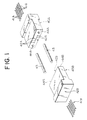
ferrule 45A of a half of an optical fiber connector comprises a plurality offiber holes 42A into which a plurality ofoptical fiber 41A are inserted. Theferrule 45B of the other half of the optical fiber connector has a structure asferrule 45A. Twofitting pins 43 are inserted intopin holes optical fibers fiber holes - The
ferrule ferrules fiber holes pin holes ferrules - When holding and fixing the molding cores in place, it is necessary to firmly fix the molding cores from both top and bottom sides without any clearance so as to precisely hold the molding cores at a fixed position without play.
- However, when forming the
ferrule - An object of the present invention is to provide a method of forming a ferrule and a mold therefor by which the ferrule can be produced with high quality.
- Another object of the present invention is to provide a method of forming a ferrule and a mold by means of which the ferrule can be manufactured at a high yield.
- According to the present invention, there is provided a method of molding ferrule of plastic resin, wherein the ferrule is provided with at least one hole having a small diameter and positioned at a predetermined position, by a mold comprising a pair of mold halves, inner members, at least one of said inner members being a positioning member, and at least one core member; characterised by the following combination of steps:-
- arranging said inner members in a first cavity, defined by said pair of mold halves, to thereby define a second cavity wherein is arranged at least one molding member forming at least one hole having a small diameter after completion of molding;
- holding said mold halves and said inner members by a clamping force CP such that at least one of said inner members is free from the clamping force and can be used as a positioning member;
- applying a force to said positioning member, which force is smaller than and separate of said clamping force, for positioning said molding member; and
- supplying a plastic resin in said second cavity to form a ferrule,
- Preferably, the force applied to said positioning member is generated by a member that generates the force in response to electric power, an elastic member, a pressurized fluid, a compressed gas, or an electromagnet.
- According to the present invention, there is provided a mold for forming a ferrule provided with at least one hole having a small diameter and being positioned at a predetermined position comprising
- a pair of mold halves defining a first cavity wherein inner members, of which at least one is a positioning member, are arranged to define a common cavity;
- at least one molding member which is disposed in said common cavity, characterised in that
- said pair of mold halves and the inner members being configurated such they may be held by a common clamping force exempt at least one inner member which is free of the clamping force and forms a positioning member for positioning said molding member; and
- a force means for applying separately from said clamping force a force to said positioning member for positioning of said molding member.
- Preferably, the pressing means comprises a member that generates the force in response to electric power, an elastic member, a pressurized fluid, a compressed gas, or an electromagnet.
- Preferably, the pin holders are positioned by a groove having at least one inclined surface, such as a V-shaped surface, or a trapezoid. The groove is connected with the pressing means for applying the holding force of the pin independent from the mold clamping force.
- Specifically, the ferrule is used for an optical fiber connector, an optical fiber switch or the like, and the hole of small diameter is formed to fit an optical fiber.
- The above-mentioned object and other objects and the above-mentioned feature and other features of the present invention will be described in detail with reference to the accompanying drawings, in which;
- Fig. 1 is a perspective view of a pair of ferrules for an optical fiber connector;
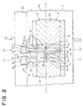
- Fig. 2 is a sectional view of a first embodiment of a mold according to the present invention;
- Fig. 3 is a sectional view of the mold shown in Fig. 2 taken along the line Z1-Z1';
- Fig. 4 is a top view of a molding ferrule half of the mold shown in Fig. 2;
- Fig. 5 is a bottom view of another molding ferrule half of the mold shown in Fig. 2;
- Fig. 6 is a disassembled perspective view showing major components of the mold;
- Fig. 7 is a sectional view of a second embodiment of a mold according to the present invention;
- Fig. 8 is a sectional view of a third embodiment of a mold according to the present invention;
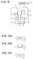
- Fig. 9 is a partial sectional view of a fourth embodiment of mold according to the present invention;
- Fig. 10a to 10c are sectional views of modifications of a positioning groove in Fig. 3;
- Fig. 11 is a perspective view of a pair of ferrules for an optical fibers switch, and
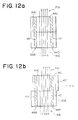
- Fig. 12a and 12b are plan views explaining modes of switching of the optical fiber switch shown in Fig. 11.
- An embodiment of a mold for forming a ferrule which can be used for an optical fiber connector, will be described with reference to Figs. 2 to 6.
- In Figs. 2 and 3, a mold comprises a molding ferrule half 1A and another molding ferrule half 1B which are accommodated in a
movable mold 21 and astationary mold 22. Apush plate 23 is mounted on thestationary mold 22.Portions 20a and 20b are defined between the molding ferrule halves 1A and 1B.Portions 20a and 20b are connected to each other to define a commonsecond cavity 20. - Molding
cores second cavity 20. - As shown in Figs. 1 and 6, a
first molding core 34 consists of a plurality ofthin pins 36 for defining the optical fiber holes 42a in theferrule 45A, and afixing block 37 for fixing thepins 36.Second molding cores 35 are pins used for defining theholes 44A of theferrule 45A. - The molding ferrule half 1A comprises a combination of a plurality of mold components (inner molding members) 2a, 3a, 4a, 5a, 6a, 7a, and 8a, while the other molding ferrule half 1B comprises a combination of a plurality of mold components (inner molding members) 2b, 3b, 4b, 5b, 6b, 7b, and 8b.
- These
mold components 2a to 8a and themold components 2b to 8b consist of the same materials which may be selected from metals and ceramics. In a specific example, themold components pins 36 andpins 35 in place, are free from the clamping force and are of cemented carbide. The mold components other than themold components - Figure 3 is a view of the mold taken along the line Z1 and Z1' in Fig. 2. In Figs. 2 and 3, the molding ferrule half 1A includes the
stationary mold component 4a, and the molding ferrule half 1B includes themovable mold component 4b. Thestationary mold component 4a and themovable mold component 4b cooperate to position thepins 36 of thefirst molding core 34 and thepins 35 of the second molding core. It should be noted that themold component 4a is fixed or stationary. Themold component 4b is movable by thepiezoelectric element 32. When themold component 4b is pressed by thepiezoelectric element 32, aspace 50 is formed between themold component 4b and theplate 3b. - The
mold components mold components - Note that the clamping force CP is applied to the molding ferrule halves 1A and 1B. The
mold component 4b and themold component 7b, however, are not affected by the clamping force CP. They receive only forces from thepiezoelectric elements - In the molding ferrule half 1A, the
mold component 2a is formed as a base plate, themold component 3a is formed as a closing plate, and the remainingmold components 4a to 8a are formed as blocks. In the same way, in the molding ferrule half 1B, themold component 2b is formed as a base plate, themold component 3b is formed as a closing plate, and the remainingmold components 4b to 8b are formed as blocks. - On the surface of the
mold component 2a, anopening 9a serving as a pocket is formed. The bottom of theopening 9a is closed by themold component 3a. Themold components opening 9a in line. At the center of the top surface of themold component 4a and at the two sides of the top surface, V-shaped moldingcore holding portions 10a and 11a are formed. The top surface of themold component 5a is formed as a flat surface which is lower than the top end face of themold component 4a. The top end face of themold component 6a is also formed as a flat surface which is slightly lower than the top end face of themold component 5a. At the center of the top surface of themold component 7a and at the two sides of the top surface,concave core grooves 13a and 14a are formed. Further, at the center of the top surface of themold component 8a and at the two sides of the top surface, concavecore holding portions - On the surface of the
mold component 2b, anopening 9b serving as a pocket is formed, and themold components opening 9b in line. At the center of the bottom surface of themold component 4b and at the two sides of the bottom surface, the core holding portions 10b and 11b are formed, respectively. The bottom surface of themold component 5b is formed as a flat surface which is positioned higher than the bottom surface of themold component 4b. Further, the bottom surface of themold component 6b is also formed as a flat surface, which is positioned slightly above the bottom surface of themold component 5b. - The bottom surface of the
mold component 7b lies at the same level as the bottom surface of themold component 4b. At the center of the bottom surface of themold component 7b and at the two sides of the bottom surface,concave core grooves 13b and 14b are formed, respectively. At the center of the bottom surface of themold component 8b and at the two sides of the bottom surface, concavecore holding portions mold component 3b is placed to abut against the top surface of themold component 2b. Insertion holes 17 and 18 are formed in themold component 3b at a position facing themold components - When the molding ferrule half 1A is assembled from the above-mentioned
mold components 2a to 8a, themold component 3a is placed so as to abut against the bottom surface of themold component 2a, themold components mold components 4a to 8a are inserted into theopening 9a of themold component 2a in a predetermined arrangement, to construct the molding ferrule half 1A. The resulting molding half 1A has a recess position 20a defining thesecond cavity 20. - When assembling the molding ferrule half 1B by means of the above-mentioned
mold components 2b to 8b, themold component 3b is placed so as to abut against the bottom surface of themold component 2b, themold components mold components 4b to 8b are inserted into theopening 9b of themold component 2b in a predetermined arrangement, to construct the molding ferrule half 1B. The resultant molding ferrule half 1B has anotherrecess 20b defining thecavity 20. - In the assembled molding ferrule halves 1A and 1B, the
mold components mold components mold components mold components mold components mold components mold components movable mold 21, while the molding ferrule half 1B is mounted on thestationary mold 22. At the top of thestationary mold 22, thepush plate 23 is fixed. Thestationary mold 22 further has throughholes 24 and 25 formed at positions corresponding to the insertion holes 17 and 18 and hasconcave holes push plate 23 facing the throughholes 24 and 25. Thepressing pin 28 is inserted in theinsertion hole 17 and the throughhole 24. The top surface of themold component 4b is placed so as to abut against the bottom surface of thepressing pin 28. Apiezoelectric element 32 is placed between the top end of thepressing pin 28 and thebottom surface 30 of theconcave hole 26. Thepiezoelectric element 32 and thepressing pin 28 constitute a pressing means for pressing themold component 4b downward. - Similarly, a pressing pin 29 is inserted into the insertion hold 18 and the through hole 25. The bottom surface of the pressing pin 29 is placed to abut against the top end of the
mold component 7b. Apiezoelectric element 33 is placed between the top end of the pressing pin 29 and thebottom surface 31 of theconcave hole 27. Thepiezoelectric element 33 and the pressing pin 29 constitute a pressing means for pressing themold component 7b downward. Note that a voltage applying means, not shown, is connected to thepiezoelectric elements - The
molding core 34, as will be clear with reference to Fig. 6 comprises a plurality ofthin pins 36, each having a small diameter and both arranged in parallel at equal distances and a connectingmember 37 which connects the base portions of thethin pin 36 to integrate them. The tips of thethin pins 36 are extremely small in diameter corresponding to the outer diameter of the optical fibers. The connectingmember 37 is formed of die steel or the like while thethin pins 36 are formed of a metal material or the like which can be precisely worked. - The
molding core 35, as shown in Fig. 6, is molded as a pin. Themolding core 35 has an outer diameter corresponding to thefitting pins 43 shown in Fig. 1. Themolding core 35 is also formed of a metal material or the like which can be precisely worked. - However, the
movable mold 21 and thestationary mold 22 shown in Fig. 2 can, as is well known, be moved relative to each other in the mold opening and closing direction. The molding ferrule half 1A is mounted on themovable mold 21, and the molding ferrule half 1B is mounted on thestationary mold 22. In this state, thethin pins 36 and the connectingmember 37 of themolding core 34 are fitted in thecore holding portions molding core 35 are fitted in thecore holding portions - When the molding ferrule halves 1A and 1B are clamped to each other, the
thin pins 36 and the connectingmember 37 of themolding core 34 are forcibly stopped by thecore holding portions 10b and 13b and the two ends of themolding core 35 are forcibly stopped by the core holding members 11b and 14b. - In this case, the tips of the pins of the
molding cores mold components piezoelectric element 32 to expand thepiezoelectric element 32, the resultant force is transmitted to themold component 4b through thepressing pin 28, so that the tips of the pins of themolding cores molding cores mold components piezoelectric element 33 to expand thepiezoelectric element 33, the resultant force is transmitted to themold component 7b through the pressing pin 29, so that the ends of the bases of the pins of themolding cores mold components piezoelectric elements molding cores piezoelectric elements molding cores - As a result, the two
molding cores cavity 20 defined byrecesses 20a and 20b. - Note that known gates and runners (not shown) are formed at the clamping surfaces of the two molding ferrule halves 1A and 1B. The runners and known runners (not shown) provided in the
movable mold 21 and thestationary mold 22 or the like, are connected with each other. - Further, the
movable mold 21 can be provided with ejector pins for ejecting the twomolding cores - According to the first embodiment, the molding ferrule halves 1A and 1B which are heated to a predetermined molding temperature, are clamped to each other. Thereafter, a fluid and high temperature plastic material (heat curing resin or thermoplastic resin) is injected into the
cavity 20 to form a predetermined mold article, that is, the optical fiber connector ferrule 45 shown in Fig. 1. - During the molding process, the pins of the
molding cores piezoelectric elements - A second embodiment of a mold according to the present invention will be described with reference to Fig. 7.
- Figure 7 is a sectional view of the mold corresponding to that of Fig. 2. In this mold shown in Fig. 7, the insertion hole 18, the through hole 25, the pressing pin 29 and the
piezoelectric element 33, which are shown in Fig. 2, are removed, and, consequently, the injection of the plastic resin in carried out through resin injection holes (not shown), and the pressing is carried out by thepiezoelectric element 32 and thepressing pin 28. The mold shown in Fig. 7 acts in the same manner as the mold shown in Fig. 2 and produces a ferrule. - A third embodiment of a mold according to the present invention will be described with reference to Fig. 8.
- Figure 8 is a sectional view of the mold corresponding to that of Fig. 2. In this mold, the
pressing pins 28 and 29 shown in Fig. 2 are removed, and springs 51 and 52 are inserted into theholes piezoelectric elements springs molding components - Alternatively, other elastic members for generating the force for pressing the
molding components springs - As seen from the second embodiment of a mold according to the present invention will be described with reference to Fig. 9.
- Figure 9 is a partial sectional view of the mold corresponding to that of Figs. 2 and 7. In this mold, a pressurized fluid such as fluid oil or a compressed gas such as compressed air, which presses the
molding component 4b through thepressing pin 28A, functions as a pressing means. O-rings - Other pressing means such as electromagnets and/or permanent magnets can also be applied.
- An excessive molding clamping force does not act on the above pressing means. As a result, a short time deterioration is prevented.
- As seen from the above described embodiments, the holding force for holding the pins of the molding cores, disposed in the cavity of the mold, is provided by a pressing means independent from the molding clamping force. As a result, it becomes possible for the pins of the molding cores to be held by the optimum force, and it is possible to hold the pins of the molding cores precisely at a fixed position without play. Thus, the molding precision of the molded ferrule can be improved sufficiently.
- Further, since the pins of the molding cores are not subjected to an excessive force such as the molding clamping force, the pins are not damaged, and therefore, the molding cores can be used for a long period of time, and the present invention is extremely advantageous in economical terms.
- Figures 10a to 10c are sectional view of modification of the V-shaped grooves 11b shown in Figs. 2 to 5. Figure 10a shows a semi V-shaped
groove 53, Fig. 10b shows atrapezoid groove 54, and Fig. 10c shows aU-shaped groove 55. Other grooves similar to those can be used. - Another ferrule of the present invention will be described with reference to Fig. 11 and Figs. 12a and 12b. These ferrules are used for an optical fiber switch, which comprises a first ferrule 45c and a
second ferrule 45B. Thesecond ferrule 45B has a structure identical to that shown in Fig. 1. The first ferrule 45c has a structure similar to theferrule 45A except that a pair of elongated throughholes 44C are formed instead of the round throughholes 44A. The formation of the first andsecond ferrules - When assembling the optical fiber switch, the
optical fibers 41A are inserted into the fiber holes 42A, while theoptical fibers 41B are inserted into the fiber holes 43B, and then thefitting pins 43 are inserted into the pin holes 44C and the pin holes 44B, to integrate theferrules - Normally, when both
ferrules optical fibers first ferrule 45C is moved by one pitch defining a distance between adjacent optical fibers, in a direction A, the fitting pins 43 are moved to the left side edges of theelongated holes 44C, to thereby change the above optical paths, as shown in Fig. 12b.
Claims (15)
- A method of molding a ferrule of plastic resin, wherein the ferrule (45A, 45B) is provided with at least one hole (42A, 42B) having a small diameter and positioned at a predetermined position, by a mold comprising:- a pair of mold halves (21, 22); inner members (4a-8a, 4b-8b), at least one of said inner members being a positioning member; and at least one molding member (35, 36); characterised by the following steps:-arranging said inner members (4a-8a, 4b-8b) in a first cavity (20), defined by said pair of mold halves (21, 22), to thereby define a second cavity (20) wherein is arranged at least one molding member (36, 35) forming at least one hole (42A, 42B) having a small diameter after completion of molding;holding said mold halves (21, 22) and said inner members (4a-8a, 4b-8b) by a clamping force (CP) such that at least one of said inner members (4a-8a, 4b-8b) is free from the clamping force and can be used as a positioning member (4b, 7b);applying a force to said positioning member, which force is smaller than and separate of said clamping force, for positioning said molding member (36, 35); andsupplying a plastic resin in said second cavity (20) to form a ferrule,
- A method of molding a ferrule according to claim 1, wherein the force to said positioning member is generated by a member which generates the force in response to electric power.
- A method of molding a ferrule according to claim 1, wherein the force to said positioning member is generated by an elastic member.
- A method of molding a ferrule according to claim 1, wherein the force to said positioning member is generated by a pressurized fluid.
- A method of molding a ferrule according to claim 1, wherein the force to said positioning member is generated by a compressed gas.
- A method of molding a ferrule according to claim 1, wherein the force to said positioning member is generated by a magnet.
- A mold for forming a ferrule provided with at least one hole having a small diameter and positioned at a predetermined position, comprising:-a pair of mold halves (21, 22) defining a first cavity (50) wherein inner members (4a-8a, 4b-8b), of which at least one is a positioning member (4b, 7b), are arranged to define a common cavity (20);at least one molding member (36, 35) which is disposed in said common cavity (20), characterised in thatsaid pair of mold halves and the inner members (4a-8a, 4b-8b) being configurated such they may be held by a common clamping force exempt at least one inner member (4b, 7b) which is free of the clamping force and forms a positioning member (4b, 7b) for positioning said molding member (36, 35); anda force means (28) for applying separately from said clamping force a force to said positioning member for positioning of said molding member (36, 35).
- A mold for forming a ferrule according to claim 7, wherein said force means comprises a member (32, 33) which generates the force in response to electric power.
- A mold for forming a ferrule according to claim 7, wherein said pressing means (51, 52) comprises an elastic member.
- A mold for forming a ferrule according to claim 7, wherein said pressing means comprises a pressurized fluid.
- A mold for forming a ferrule according to claim 7, wherein said pressing means comprises a compressed gas.
- A mold for forming a ferrule according to claim 7, wherein said pressing means comprises a magnet means.
- A mold for forming a ferrule according to claim 7, wherein said inner member comprises a groove having at least one inclined surface, such as a V-shaped surface, a trapezoid.
- A mold for forming a ferrule according to claim 7, wherein said ferrule is used for an optical fiber connector, an optical fiber switch or the like, and
said hole having a small diameter is formed to fit an optical fiber (41A). - A mold for forming a ferrule according to claim 7, wherein said molding ferrule cores further comprises at least one additional pin member (35) for forming a hole (44A) through which a connecting pin (43) is inserted.
Applications Claiming Priority (2)
| Application Number | Priority Date | Filing Date | Title |
|---|---|---|---|
| JP149877/91 | 1991-05-24 | ||
| JP03149877A JP3088779B2 (en) | 1991-05-24 | 1991-05-24 | Mold for molding ferrule for optical connector |
Publications (2)
| Publication Number | Publication Date |
|---|---|
| EP0514923A1 EP0514923A1 (en) | 1992-11-25 |
| EP0514923B1 true EP0514923B1 (en) | 1996-12-11 |
Family
ID=15484594
Family Applications (1)
| Application Number | Title | Priority Date | Filing Date |
|---|---|---|---|
| EP92108678A Expired - Lifetime EP0514923B1 (en) | 1991-05-24 | 1992-05-22 | Method of forming ferrule for optical fiber connector and mold thereof |
Country Status (5)
| Country | Link |
|---|---|
| US (1) | US5269998A (en) |
| EP (1) | EP0514923B1 (en) |
| JP (1) | JP3088779B2 (en) |
| CA (1) | CA2069285C (en) |
| DE (1) | DE69215752T2 (en) |
Families Citing this family (25)
| Publication number | Priority date | Publication date | Assignee | Title |
|---|---|---|---|---|
| FR2689253B1 (en) * | 1992-03-24 | 1997-01-24 | Souriau & Cie | MOLDING DEVICE COMPRISING A PIN GUIDE COUNTERPIECE FOR MOLDING FIBER OPTIC CONNECTOR BOLTS, AND MOLDED BUCKLE USING SUCH A DEVICE. |
| JPH0586563U (en) * | 1992-05-07 | 1993-11-22 | チョウ、クォ・ホァ | Paper sandwich |
| JP3276787B2 (en) * | 1994-10-07 | 2002-04-22 | 古河電気工業株式会社 | Ferrule manufacturing method |
| US5720907A (en) * | 1995-04-24 | 1998-02-24 | Lucent Technologies Inc. | Method for manufacturing an optical connector assembly |
| KR0156970B1 (en) * | 1995-08-01 | 1998-12-15 | 유기범 | Molding apparatus for manufacturing multi-core connectors for optical cable connection |
| TW304233B (en) * | 1995-09-07 | 1997-05-01 | At & T Corp | |
| US5786002A (en) * | 1996-04-04 | 1998-07-28 | Siecor Corporation | Guide block assembly for aligning bore forming pins during molding of multi-fiber optical connector ferrules |
| US6201915B1 (en) | 1998-10-13 | 2001-03-13 | Physical Optics Corporation | High efficiency lighting system having a remote light source |
| JP3271707B2 (en) * | 1999-11-19 | 2002-04-08 | 財団法人工業技術研究院 | Method for manufacturing mold with high dimensional accuracy and method for manufacturing separated type optical fiber connector ferrule |
| JP2001215358A (en) * | 2000-01-31 | 2001-08-10 | Molex Inc | Optical fiber ferrule and its manufacturing method |
| US20030107159A1 (en) * | 2000-07-03 | 2003-06-12 | Minoru Adachi | Bonding method |
| US6663377B1 (en) * | 2000-07-21 | 2003-12-16 | Corning Cable Systems Llc | Precision insert for molding multi-fiber connectors and method for manufacturing thereof |
| US6767199B2 (en) * | 2000-07-21 | 2004-07-27 | Corning Cable Systems Llc | Precision insert for molding multi-fiber connectors and method for manufacturing thereof |
| DE10047363B4 (en) * | 2000-09-25 | 2006-03-02 | Siemens Ag | Surface pressure-generating device |
| JP4346255B2 (en) * | 2001-04-06 | 2009-10-21 | 古河電気工業株式会社 | Multi-fiber optical connector ferrule manufacturing equipment |
| US6709252B2 (en) * | 2001-07-10 | 2004-03-23 | Asm Technology Singapore Pte Ltd | Molding apparatus |
| US20050236725A1 (en) * | 2004-04-23 | 2005-10-27 | Niewels Joachim J | Method and apparatus for countering mold deflection and misalignment using active material elements |
| US20050236727A1 (en) * | 2004-04-23 | 2005-10-27 | Niewels Joachim J | Method and apparatus for mold component locking using active material elements |
| US7901196B2 (en) * | 2008-03-03 | 2011-03-08 | Asm Technology Singapore Pte Ltd | Molding apparatus incorporating pressure uniformity adjustment |
| CN102230991B (en) * | 2009-10-23 | 2013-01-09 | 鸿富锦精密工业(深圳)有限公司 | Optical fiber coupling connector |
| TW201121762A (en) * | 2009-12-25 | 2011-07-01 | Hon Hai Prec Ind Co Ltd | Insert core and insert molding product |
| TW201142392A (en) * | 2010-05-20 | 2011-12-01 | Hon Hai Prec Ind Co Ltd | Mold for making optical fiber coupling connector |
| TW201206679A (en) * | 2010-08-06 | 2012-02-16 | Hon Hai Prec Ind Co Ltd | Mold for making optical fiber coupling connector |
| TW201242741A (en) * | 2011-04-25 | 2012-11-01 | Hon Hai Prec Ind Co Ltd | Mold for molding optical fiber connector and method for fabricating same |
| CN102756437B (en) * | 2011-04-26 | 2016-09-28 | 深圳市宇轩网络技术有限公司 | Joints of optical fibre mould and preparation method thereof |
Family Cites Families (7)
| Publication number | Priority date | Publication date | Assignee | Title |
|---|---|---|---|---|
| US4342549A (en) * | 1978-12-11 | 1982-08-03 | Lemelson Jerome H | Apparatus for coding articles |
| US4531702A (en) * | 1982-11-02 | 1985-07-30 | Polaroid Corporation | Injection mold for forming optical fiber connector |
| CA1245818A (en) * | 1984-05-03 | 1988-12-06 | Polaroid Corporation | Molding apparatus |
| US4711752A (en) * | 1984-06-22 | 1987-12-08 | Itt Corporation | Method and apparatus for molding fiber optic connector ferrule |
| US4649616A (en) * | 1984-11-01 | 1987-03-17 | Amp Incorporated | Method for molding a plastic ferrule for use in connectors for optical fibers |
| JPS6427401A (en) * | 1987-07-22 | 1989-01-30 | Kubota Ltd | Structure of connecting part for working device |
| US5034170A (en) * | 1989-11-07 | 1991-07-23 | Bell Communications Research, Inc. | High-precision adjustable injection molding of single-mode fiber optic connectors |
-
1991
- 1991-05-24 JP JP03149877A patent/JP3088779B2/en not_active Expired - Lifetime
-
1992
- 1992-05-22 DE DE69215752T patent/DE69215752T2/en not_active Expired - Fee Related
- 1992-05-22 CA CA002069285A patent/CA2069285C/en not_active Expired - Fee Related
- 1992-05-22 US US07/887,012 patent/US5269998A/en not_active Expired - Fee Related
- 1992-05-22 EP EP92108678A patent/EP0514923B1/en not_active Expired - Lifetime
Also Published As
| Publication number | Publication date |
|---|---|
| JPH04347605A (en) | 1992-12-02 |
| DE69215752T2 (en) | 1997-06-12 |
| CA2069285A1 (en) | 1992-11-25 |
| DE69215752D1 (en) | 1997-01-23 |
| US5269998A (en) | 1993-12-14 |
| JP3088779B2 (en) | 2000-09-18 |
| EP0514923A1 (en) | 1992-11-25 |
| CA2069285C (en) | 1996-01-30 |
Similar Documents
| Publication | Publication Date | Title |
|---|---|---|
| US5269998A (en) | Method of forming ferrule for an optical fiber connector and a mold therefor | |
| JP4061682B2 (en) | Method for forming optical connector ferrule | |
| CN103189774B (en) | Cranse for optical delivery body | |
| US4753515A (en) | Method for assembling flat type plastic multifiber connectors | |
| US7597836B2 (en) | Mold apparatus and method for injection molding | |
| CA2249279A1 (en) | Method of mutually positioning a pair of shaping-tool halves facing each other, and shaping tool for the manufacture of precision-made articles, in particular contact lenses | |
| US5185825A (en) | Optical switching connector | |
| JPH07318761A (en) | Multi-fiber optical connector | |
| US6342170B1 (en) | Fabrication method and forming mold for multi-fiber optical-connector ferrules | |
| US7891965B2 (en) | Mold | |
| US6702962B2 (en) | Manufacturing method of ferrule for multi optical connector | |
| JPH06278141A (en) | Plastic molding equipment | |
| JP2008155577A (en) | Lens molding mold and lens manufacturing method | |
| JP2000289058A (en) | Ferrule molding die and ferrule for optical connector | |
| JP2893231B2 (en) | Ferrule for optical connector and manufacturing method thereof | |
| KR100403668B1 (en) | Mold for molding an optical fiber connecting device and a method for fabricating the device using the same | |
| JP3209586B2 (en) | Injection molding die and injection molding method | |
| KR100280329B1 (en) | Multi-optical connectors and multi-conductor connectors using plastic multi-conductor connector ferrules | |
| US20020157774A1 (en) | Ferrule manufacture method and ferrule | |
| JPH08132486A (en) | Optical connector molding die and molding method thereof | |
| CN223141099U (en) | Split terminal and its injection molding mold | |
| US6767196B2 (en) | Manufacturing apparatus for producing a multi-fiber optical ferrule | |
| JP2011011384A (en) | Molding apparatus | |
| JP2003084172A (en) | Method and die for manufacturing fiber support for optical connector | |
| JP2000231036A (en) | Method and device for transfer molding for manufacture of optical fiber connector |
Legal Events
| Date | Code | Title | Description |
|---|---|---|---|
| PUAI | Public reference made under article 153(3) epc to a published international application that has entered the european phase |
Free format text: ORIGINAL CODE: 0009012 |
|
| AK | Designated contracting states |
Kind code of ref document: A1 Designated state(s): DE FR GB IT |
|
| 17P | Request for examination filed |
Effective date: 19930521 |
|
| 17Q | First examination report despatched |
Effective date: 19940525 |
|
| GRAG | Despatch of communication of intention to grant |
Free format text: ORIGINAL CODE: EPIDOS AGRA |
|
| GRAH | Despatch of communication of intention to grant a patent |
Free format text: ORIGINAL CODE: EPIDOS IGRA |
|
| GRAH | Despatch of communication of intention to grant a patent |
Free format text: ORIGINAL CODE: EPIDOS IGRA |
|
| GRAA | (expected) grant |
Free format text: ORIGINAL CODE: 0009210 |
|
| AK | Designated contracting states |
Kind code of ref document: B1 Designated state(s): DE FR GB IT |
|
| ITF | It: translation for a ep patent filed | ||
| REF | Corresponds to: |
Ref document number: 69215752 Country of ref document: DE Date of ref document: 19970123 |
|
| ET | Fr: translation filed | ||
| PLBE | No opposition filed within time limit |
Free format text: ORIGINAL CODE: 0009261 |
|
| STAA | Information on the status of an ep patent application or granted ep patent |
Free format text: STATUS: NO OPPOSITION FILED WITHIN TIME LIMIT |
|
| 26N | No opposition filed | ||
| REG | Reference to a national code |
Ref country code: GB Ref legal event code: IF02 |
|
| PGFP | Annual fee paid to national office [announced via postgrant information from national office to epo] |
Ref country code: FR Payment date: 20040510 Year of fee payment: 13 |
|
| PGFP | Annual fee paid to national office [announced via postgrant information from national office to epo] |
Ref country code: GB Payment date: 20040519 Year of fee payment: 13 |
|
| PGFP | Annual fee paid to national office [announced via postgrant information from national office to epo] |
Ref country code: DE Payment date: 20040603 Year of fee payment: 13 |
|
| PG25 | Lapsed in a contracting state [announced via postgrant information from national office to epo] |
Ref country code: IT Free format text: LAPSE BECAUSE OF NON-PAYMENT OF DUE FEES;WARNING: LAPSES OF ITALIAN PATENTS WITH EFFECTIVE DATE BEFORE 2007 MAY HAVE OCCURRED AT ANY TIME BEFORE 2007. THE CORRECT EFFECTIVE DATE MAY BE DIFFERENT FROM THE ONE RECORDED. Effective date: 20050522 Ref country code: GB Free format text: LAPSE BECAUSE OF NON-PAYMENT OF DUE FEES Effective date: 20050522 |
|
| PG25 | Lapsed in a contracting state [announced via postgrant information from national office to epo] |
Ref country code: DE Free format text: LAPSE BECAUSE OF NON-PAYMENT OF DUE FEES Effective date: 20051201 |
|
| GBPC | Gb: european patent ceased through non-payment of renewal fee |
Effective date: 20050522 |
|
| PG25 | Lapsed in a contracting state [announced via postgrant information from national office to epo] |
Ref country code: FR Free format text: LAPSE BECAUSE OF NON-PAYMENT OF DUE FEES Effective date: 20060131 |
|
| REG | Reference to a national code |
Ref country code: FR Ref legal event code: ST Effective date: 20060131 |