EP0513670B1 - Method for making a shock absorber for washing machines and shock absorber thus made - Google Patents
Method for making a shock absorber for washing machines and shock absorber thus made Download PDFInfo
- Publication number
- EP0513670B1 EP0513670B1 EP92107738A EP92107738A EP0513670B1 EP 0513670 B1 EP0513670 B1 EP 0513670B1 EP 92107738 A EP92107738 A EP 92107738A EP 92107738 A EP92107738 A EP 92107738A EP 0513670 B1 EP0513670 B1 EP 0513670B1
- Authority
- EP
- European Patent Office
- Prior art keywords
- tubular casing
- shock absorber
- tub
- piston
- blank
- Prior art date
- Legal status (The legal status is an assumption and is not a legal conclusion. Google has not performed a legal analysis and makes no representation as to the accuracy of the status listed.)
- Expired - Lifetime
Links
- 239000006096 absorbing agent Substances 0.000 title claims description 24
- 230000035939 shock Effects 0.000 title claims description 24
- 238000000034 method Methods 0.000 title claims description 14
- 238000005406 washing Methods 0.000 title claims description 6
- 239000002184 metal Substances 0.000 claims description 10
- 239000000463 material Substances 0.000 claims description 6
- 230000010355 oscillation Effects 0.000 claims description 6
- 239000002783 friction material Substances 0.000 claims description 4
- 238000004900 laundering Methods 0.000 claims description 3
- 229910000831 Steel Inorganic materials 0.000 claims description 2
- 238000003490 calendering Methods 0.000 claims description 2
- 238000010276 construction Methods 0.000 claims description 2
- 239000010959 steel Substances 0.000 claims description 2
- 238000004519 manufacturing process Methods 0.000 description 5
- 230000015572 biosynthetic process Effects 0.000 description 4
- 238000003466 welding Methods 0.000 description 3
- 238000005520 cutting process Methods 0.000 description 2
- 238000005452 bending Methods 0.000 description 1
- 238000001035 drying Methods 0.000 description 1
- 230000008030 elimination Effects 0.000 description 1
- 238000003379 elimination reaction Methods 0.000 description 1
- 238000002347 injection Methods 0.000 description 1
- 239000007924 injection Substances 0.000 description 1
- 238000001746 injection moulding Methods 0.000 description 1
- 238000003780 insertion Methods 0.000 description 1
- 230000037431 insertion Effects 0.000 description 1
Images
Classifications
-
- F—MECHANICAL ENGINEERING; LIGHTING; HEATING; WEAPONS; BLASTING
- F16—ENGINEERING ELEMENTS AND UNITS; GENERAL MEASURES FOR PRODUCING AND MAINTAINING EFFECTIVE FUNCTIONING OF MACHINES OR INSTALLATIONS; THERMAL INSULATION IN GENERAL
- F16F—SPRINGS; SHOCK-ABSORBERS; MEANS FOR DAMPING VIBRATION
- F16F7/00—Vibration-dampers; Shock-absorbers
- F16F7/08—Vibration-dampers; Shock-absorbers with friction surfaces rectilinearly movable along each other
- F16F7/09—Vibration-dampers; Shock-absorbers with friction surfaces rectilinearly movable along each other in dampers of the cylinder-and-piston type
-
- F—MECHANICAL ENGINEERING; LIGHTING; HEATING; WEAPONS; BLASTING
- F16—ENGINEERING ELEMENTS AND UNITS; GENERAL MEASURES FOR PRODUCING AND MAINTAINING EFFECTIVE FUNCTIONING OF MACHINES OR INSTALLATIONS; THERMAL INSULATION IN GENERAL
- F16F—SPRINGS; SHOCK-ABSORBERS; MEANS FOR DAMPING VIBRATION
- F16F9/00—Springs, vibration-dampers, shock-absorbers, or similarly-constructed movement-dampers using a fluid or the equivalent as damping medium
- F16F9/32—Details
- F16F9/3271—Assembly or repair
Definitions
- the invention relates to a method for making a shock absorber for washing machines, particularly for laundry washers or combined laundry washers and driers, and to a shock absorber adapted to be mounted between a bottom structure of the machine and the laundering tub containing the rotatable drum, for effectively dampening the oscillations of the tub and drum assembly resulting from the rotation of the drum at the laundering and spin-drying speeds in the course of the execution of any selected laundering program.
- shock absorbers for the above defined purpose.
- These known shock absorbers comprise a tubular metal casing and a piston adapted to slide back and forth within the casing and provided with a plurality of braking elements made of a conventional low-friction material and acting to dampen the oscillations of the tub and drum assembly by the effect of friction between the braking elements and the interior wall surface of the tubular casing.
- the tubular casing and the piston have their free ends connected respectively to a housing bottom structure of the machine and a lower part of the tub containing the rotatable drum.
- the metal casing is made of a drawn pipe stock or by welding a coiled sheet metal blank along its contiguous edges, the resulting metal casing being then enclosed in a plastic support structure having one open end by way of which the piston of the shock absorber is to be inserted, and a closed end configured so as to permit it to be hinged, as by means of a bolt, to the housing bottom structure of the machine.
- shock absorbers of this type it is in any case extremely difficult to obtain a perfectly smooth interior wall surface of the tubular casings for frictionally cooperating with the braking elements of the piston during its reciprocation. This is because the formation of surface irregularities is practically inavoidable in the case of welded pipes, due to the welding operation, and in the case of drawn pipe stock, due to attrition in the course of the drawing operation.
- tubular casings of theses types are cut to the required length from pipe stock material of greater length, there is the additional danger of the formation of burrs at the cutting locations.
- a shock absorber for washing machines in particularly laundry washers or combined laundry washers and driers, operable to dampen the oscillations of the tub and drum assembly of machines of this type resulting from the rotation of the drum during execution of any selected laundering program.
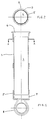
- the shock absorber is of substantially conventional construction and composed of a tubular metal casing 3 as shown in fig. 1, and a piston adapted to slide back and forth in the internal bore 4 of the tubular casing and provided with a plurality of braking elements of a low-friction material (the piston and braking elements being not shown in the drawings), acting to produce a braking action as a result of friction between them and the internal wall surface of the tubular casing to thereby dampen the oscillations of the tub and drum assembly.
- the tubular casing 3 is enclosed in a plastic support structure 5 having an open end 6 for the insertion of the piston, the free end of which is provided with an eyelet for mounting it on a bolt projecting from a lower part of the lye tub of the machine, and a closed end 7 formed in one piece with an eyelet 8 for connection to a bolt (not shown) provided on the housing bottom structure of the machine.
- shock absorber is substantially identical to the one described in Italian Patent Application no. 34061-B/87, filed on 4-11-1987 in the name of Industrie Zanussi S.p.A. which is incorporated herein by reference.
- the method to be described includes a first step of providing a planar metal blank (steel or the like) of quadrangular shape and with perfectly smooth main surfaces, this blank having been previously cut to the dimensions required for making the tubular casing from a stock material conventionally supplied in coils.
- the thus provided blank is circularly coiled upon itself about its vertical side in a bending operation, for instance by calendering, with a predetermined coiling diameter corresponding to the diameter of the tubular casing to be made, and in such a manner that the two facing boundary edges of the thus coiled blank are spaced from one another by a very small distance or gap 9 (cf. fig. 2) extending over the full length of the tubular casing for reasons to be explained as the description proceeds.
- the thus obtained tubular metal casing is inserted into a conventional plastic processing machine, for instance an injection-moulding machine, in which the tubular casing is slipped onto a mandrel of the injection mould.
- a plastic material is injection-moulded about the tubular casing to thereby form the support structure 5 with the desired shape and dimensions.
- each tubular casing is obtained by performing the simple manufacturing steps described on a readily available and economically convenient type of material instead of having to employ a more costly material such as welded or drawn pipe stock, as in the case of known shock absorbers, and thanks to the elimination of the necessity of additional manufacturing steps such as cutting each tubular casing to the desired length, the invention results in a considerably simplified and thus more economical manufacturing process.
Landscapes
- Engineering & Computer Science (AREA)
- General Engineering & Computer Science (AREA)
- Mechanical Engineering (AREA)
- Main Body Construction Of Washing Machines And Laundry Dryers (AREA)
- Packaging Of Machine Parts And Wound Products (AREA)
- Fluid-Damping Devices (AREA)
Description
- The invention relates to a method for making a shock absorber for washing machines, particularly for laundry washers or combined laundry washers and driers, and to a shock absorber adapted to be mounted between a bottom structure of the machine and the laundering tub containing the rotatable drum, for effectively dampening the oscillations of the tub and drum assembly resulting from the rotation of the drum at the laundering and spin-drying speeds in the course of the execution of any selected laundering program.
- Known washing machines are provided with shock absorbers for the above defined purpose. These known shock absorbers comprise a tubular metal casing and a piston adapted to slide back and forth within the casing and provided with a plurality of braking elements made of a conventional low-friction material and acting to dampen the oscillations of the tub and drum assembly by the effect of friction between the braking elements and the interior wall surface of the tubular casing. The tubular casing and the piston have their free ends connected respectively to a housing bottom structure of the machine and a lower part of the tub containing the rotatable drum. In a known shock absorber of this type as described in Italian Patent Application no. 34061-B/87, filed on 4-11-1987 in the name of Industrie Zanussi S.p.A., the metal casing is made of a drawn pipe stock or by welding a coiled sheet metal blank along its contiguous edges, the resulting metal casing being then enclosed in a plastic support structure having one open end by way of which the piston of the shock absorber is to be inserted, and a closed end configured so as to permit it to be hinged, as by means of a bolt, to the housing bottom structure of the machine.
- In practical embodiments of shock absorbers of this type it is in any case extremely difficult to obtain a perfectly smooth interior wall surface of the tubular casings for frictionally cooperating with the braking elements of the piston during its reciprocation. This is because the formation of surface irregularities is practically inavoidable in the case of welded pipes, due to the welding operation, and in the case of drawn pipe stock, due to attrition in the course of the drawing operation. When tubular casings of theses types are cut to the required length from pipe stock material of greater length, there is the additional danger of the formation of burrs at the cutting locations.
- The repeated contact of the piston braking elements with these surface irregularities or burrs of the tubular casing in operation of the machine may result in the braking elements being permanently deformed or damaged, thus impairing the reliability of the shock absorber in terms of its capability of dampening the oscillations of the tub.
- It is therefore an object of the invention to eliminate these shortcomings by providing a novel method for making a shock absorber for washing machines, and a thus made shock absorber featuring the characteristics as set forth in the appended claims.
- The characteristics of the invention will become more clearly evident from the following description, given by way of example with reference to the accompanying drawings, wherein:
- fig. 1
- shows a longitudinally sectioned view of a shock absorber made by the method according to the invention, and
- fig. 2
- shows a sectional view of the shock absorber taken along the line A-A in fig. 1.
- With reference to the figures of the drawings, there is diagrammatically shown a structural particular of a shock absorber for washing machines, in particularly laundry washers or combined laundry washers and driers, operable to dampen the oscillations of the tub and drum assembly of machines of this type resulting from the rotation of the drum during execution of any selected laundering program.
- The shock absorber is of substantially conventional construction and composed of a
tubular metal casing 3 as shown in fig. 1, and a piston adapted to slide back and forth in theinternal bore 4 of the tubular casing and provided with a plurality of braking elements of a low-friction material (the piston and braking elements being not shown in the drawings), acting to produce a braking action as a result of friction between them and the internal wall surface of the tubular casing to thereby dampen the oscillations of the tub and drum assembly. Thetubular casing 3 is enclosed in aplastic support structure 5 having anopen end 6 for the insertion of the piston, the free end of which is provided with an eyelet for mounting it on a bolt projecting from a lower part of the lye tub of the machine, and a closedend 7 formed in one piece with an eyelet 8 for connection to a bolt (not shown) provided on the housing bottom structure of the machine. - The thus configured shock absorber is substantially identical to the one described in Italian Patent Application no. 34061-B/87, filed on 4-11-1987 in the name of Industrie Zanussi S.p.A. which is incorporated herein by reference.
- The following description now refers to the method according to the invention for making the assembly composed of
tubular casing 3 andplastic support structure 5, the description of the method employed for making the piston with its braking elements being omitted by reason of its being per se known. - The method to be described includes a first step of providing a planar metal blank (steel or the like) of quadrangular shape and with perfectly smooth main surfaces, this blank having been previously cut to the dimensions required for making the tubular casing from a stock material conventionally supplied in coils. In a second step of the method, the thus provided blank is circularly coiled upon itself about its vertical side in a bending operation, for instance by calendering, with a predetermined coiling diameter corresponding to the diameter of the tubular casing to be made, and in such a manner that the two facing boundary edges of the thus coiled blank are spaced from one another by a very small distance or gap 9 (cf. fig. 2) extending over the full length of the tubular casing for reasons to be explained as the description proceeds.
- In a third step of the method, the thus obtained tubular metal casing is inserted into a conventional plastic processing machine, for instance an injection-moulding machine, in which the tubular casing is slipped onto a mandrel of the injection mould.
- In a subsequent fourth step of the method, a plastic material is injection-moulded about the tubular casing to thereby form the
support structure 5 with the desired shape and dimensions. - The advantages that may be obtained by the described manufacturing method are clearly evident: In the first place, since the
tubular casing 3 of each shock absorber of this type is formed of a perfectly smooth and planar metal blank previously cut to the desired dimensions, the inner surface of the finished tubular casing will allways be perfectly smooth, as the further manufacturing process does not include any steps, such as drawing or welding operations, which might result in the formation of surface irregularities. On the other hand, since the thus formed tubular casing does not have to be cut to its final length, the formation of burrs on the inner surface is effectively avoided. This again is effective to securely avoid any deformation or damage of the braking elements of the piston of the shock absorber as a result of the friction between the braking elements and the internal surface of the tubular casing caused by the reciprocation of the piston within the tubular casing, thus ensuring reliable operation and a fully satisfactory dampening action of the described shock absorber. - Inasmuch, moreover, as each tubular casing is obtained by performing the simple manufacturing steps described on a readily available and economically convenient type of material instead of having to employ a more costly material such as welded or drawn pipe stock, as in the case of known shock absorbers, and thanks to the elimination of the necessity of additional manufacturing steps such as cutting each tubular casing to the desired length, the invention results in a considerably simplified and thus more economical manufacturing process.
Claims (3)
- A method for making a shock absorber for washing machines, particularly for laundry washers or combined laundry washers and driers comprising a laundring tub and a rotatable drum for containing the laundry, said shock absorber being composed of a tubular casing enclosed in a plastic support structure, and a piston adapted to reciprocate within said tubular casing and provided with a plurality of braking elements made of a conventional low-friction material and adapted to dampen the oscillations of the tub and drum assembly by friction generated between said braking elements and the inner surface of said tubular casing, said tubular casing and said piston having their free ends connected respectively to a housing bottom structure of the machine and a lower part of said tub, said method being characterized by including a first step of providing a planar blank preferably of quadrangular shape with perfectly smooth main surfaces, said blank having previously been cut from a stock material to the dimensions corresponding to those required for said tubular casing, a second step in which said planar blank is circularly coiled upon itself about its vertical side in a folding operation, for instance a calendering operation or the like, with a predetermined coiling diameter corresponding to the diameter of said tubular casing, and in a manner resulting in that the two mutually facing boundary edges of the thus coiled blank are spaced from one another by a slight distance, a third step in which the thus formed tubular casing is inserted into a conventional plastic processing machine, and a fourth step in which said plastic support structure is injection-moulded to its desired final shape and dimensions about the outer surface of said tubular casing.
- A method according to claim 1, characterized in that said planar blank is made of a metal (steel or the like).
- A shock absorber made by performing the method according to claims 1 and 2, comprising a tubular casing preferably made of metal and enclosed in a plastic support structure, and a piston adapted to reciprocate within said tubular casing and provided with braking elements made of a conventional low-friction material, said tubular casing and said piston being adapted to have their free ends connected respectively to a housing bottom structure of the machine and to a lower part of the laundering tub, characterized in that said tubular casing (3) is of an open construction with its mutually facing boundary edges spaced from one another by a slight distance (9) over the full length of said casing.
Applications Claiming Priority (2)
| Application Number | Priority Date | Filing Date | Title |
|---|---|---|---|
| ITPN910028 | 1991-05-14 | ||
| ITPN910028A IT1250389B (en) | 1991-05-14 | 1991-05-14 | MANUFACTURING PROCEDURE OF A SHOCK ABSORBER FOR WASHING MACHINES AND SHOCK ABSORBER SO OBTAINED. |
Publications (2)
| Publication Number | Publication Date |
|---|---|
| EP0513670A1 EP0513670A1 (en) | 1992-11-19 |
| EP0513670B1 true EP0513670B1 (en) | 1995-01-11 |
Family
ID=11394528
Family Applications (1)
| Application Number | Title | Priority Date | Filing Date |
|---|---|---|---|
| EP92107738A Expired - Lifetime EP0513670B1 (en) | 1991-05-14 | 1992-05-07 | Method for making a shock absorber for washing machines and shock absorber thus made |
Country Status (4)
| Country | Link |
|---|---|
| EP (1) | EP0513670B1 (en) |
| DE (1) | DE69201160T2 (en) |
| ES (1) | ES2071371T3 (en) |
| IT (1) | IT1250389B (en) |
Families Citing this family (1)
| Publication number | Priority date | Publication date | Assignee | Title |
|---|---|---|---|---|
| DE102011076200A1 (en) * | 2011-05-20 | 2012-11-22 | Bayerische Motoren Werke Aktiengesellschaft | Oil-filled two pipe-telescopic vibration damper for use in motor car, has piston displaceable in cylinder, and outer pipe connected with fastening element in force-fit and/or form-fit manner over fiber composite material of fastening device |
Family Cites Families (3)
| Publication number | Priority date | Publication date | Assignee | Title |
|---|---|---|---|---|
| FR1087894A (en) * | 1953-08-06 | 1955-03-01 | Braking device that can act as shock absorber | |
| US3795201A (en) * | 1970-01-28 | 1974-03-05 | C Tack | Railway car roll dampening friction device |
| IT213423Z2 (en) * | 1987-11-04 | 1989-11-27 | Pirelli | SHOCK ABSORBER DEVICE FOR WASHING MACHINE. |
-
1991
- 1991-05-14 IT ITPN910028A patent/IT1250389B/en active IP Right Grant
-
1992
- 1992-05-07 EP EP92107738A patent/EP0513670B1/en not_active Expired - Lifetime
- 1992-05-07 DE DE69201160T patent/DE69201160T2/en not_active Expired - Fee Related
- 1992-05-07 ES ES92107738T patent/ES2071371T3/en not_active Expired - Lifetime
Also Published As
| Publication number | Publication date |
|---|---|
| EP0513670A1 (en) | 1992-11-19 |
| DE69201160D1 (en) | 1995-02-23 |
| ITPN910028A1 (en) | 1992-11-14 |
| ES2071371T3 (en) | 1995-06-16 |
| ITPN910028A0 (en) | 1991-05-14 |
| DE69201160T2 (en) | 1995-05-11 |
| IT1250389B (en) | 1995-04-07 |
Similar Documents
| Publication | Publication Date | Title |
|---|---|---|
| JP4494814B2 (en) | Union type damper | |
| US6334341B1 (en) | Cylinder washing machine | |
| EP1813707B1 (en) | Tub for washing machine and method of manufacturing the same | |
| US2896889A (en) | Flexible retainer | |
| DE60013192T2 (en) | Sensor for detecting both water level and vibration in a washing machine | |
| US6367601B1 (en) | Friction damper for washing machines | |
| EP0513670A1 (en) | Method for making a shock absorber for washing machines and shock absorber thus made | |
| DE19603710A1 (en) | Washer dryer, for minimised noise during washing and spinning | |
| EP0315076A2 (en) | Vibration dampening device for a laundry washing machine | |
| EP0926290B1 (en) | Washing machine with improved anchoring means for the washing assembly | |
| KR100304558B1 (en) | Damper for washing machine | |
| US20070204659A1 (en) | Damper Pin In Drum Type Washing Machine | |
| KR20200076427A (en) | Damper for washing machine | |
| KR950009091Y1 (en) | Evaporate tank of a whashing machine | |
| JP3164538B2 (en) | Snubber base for washing machine damper assembly | |
| KR100797464B1 (en) | Pulley of Drum Washing Machine | |
| KR101175732B1 (en) | Damper structure of drum type washing machine | |
| KR101021743B1 (en) | Damper structure of the washing machine | |
| EP0926291B1 (en) | Washing machine with improved anchoring means for the washing assembly | |
| US20050204559A1 (en) | Expanded clamping band for washer | |
| KR100348266B1 (en) | A damper for drum type washers | |
| RU1827958C (en) | Apparatus for hardening finishing of inner end surfaces | |
| KR101137312B1 (en) | drum washing machine | |
| KR20040046952A (en) | spindle shaft manufacturing process of wash machine | |
| JP2563335B2 (en) | Anti-vibration device for dehydration washing machine |
Legal Events
| Date | Code | Title | Description |
|---|---|---|---|
| PUAI | Public reference made under article 153(3) epc to a published international application that has entered the european phase |
Free format text: ORIGINAL CODE: 0009012 |
|
| AK | Designated contracting states |
Kind code of ref document: A1 Designated state(s): DE ES FR GB IT |
|
| 17P | Request for examination filed |
Effective date: 19930203 |
|
| 17Q | First examination report despatched |
Effective date: 19940317 |
|
| ITF | It: translation for a ep patent filed | ||
| GRAA | (expected) grant |
Free format text: ORIGINAL CODE: 0009210 |
|
| AK | Designated contracting states |
Kind code of ref document: B1 Designated state(s): DE ES FR GB IT |
|
| ET | Fr: translation filed | ||
| REF | Corresponds to: |
Ref document number: 69201160 Country of ref document: DE Date of ref document: 19950223 |
|
| REG | Reference to a national code |
Ref country code: ES Ref legal event code: FG2A Ref document number: 2071371 Country of ref document: ES Kind code of ref document: T3 |
|
| PLBE | No opposition filed within time limit |
Free format text: ORIGINAL CODE: 0009261 |
|
| STAA | Information on the status of an ep patent application or granted ep patent |
Free format text: STATUS: NO OPPOSITION FILED WITHIN TIME LIMIT |
|
| 26N | No opposition filed | ||
| REG | Reference to a national code |
Ref country code: GB Ref legal event code: IF02 |
|
| PGFP | Annual fee paid to national office [announced via postgrant information from national office to epo] |
Ref country code: FR Payment date: 20020411 Year of fee payment: 11 |
|
| PGFP | Annual fee paid to national office [announced via postgrant information from national office to epo] |
Ref country code: GB Payment date: 20020417 Year of fee payment: 11 |
|
| PGFP | Annual fee paid to national office [announced via postgrant information from national office to epo] |
Ref country code: DE Payment date: 20020423 Year of fee payment: 11 |
|
| PGFP | Annual fee paid to national office [announced via postgrant information from national office to epo] |
Ref country code: ES Payment date: 20020509 Year of fee payment: 11 |
|
| PG25 | Lapsed in a contracting state [announced via postgrant information from national office to epo] |
Ref country code: GB Free format text: LAPSE BECAUSE OF NON-PAYMENT OF DUE FEES Effective date: 20030507 |
|
| PG25 | Lapsed in a contracting state [announced via postgrant information from national office to epo] |
Ref country code: ES Free format text: LAPSE BECAUSE OF NON-PAYMENT OF DUE FEES Effective date: 20030508 |
|
| PG25 | Lapsed in a contracting state [announced via postgrant information from national office to epo] |
Ref country code: DE Free format text: LAPSE BECAUSE OF NON-PAYMENT OF DUE FEES Effective date: 20031202 |
|
| GBPC | Gb: european patent ceased through non-payment of renewal fee |
Effective date: 20030507 |
|
| PG25 | Lapsed in a contracting state [announced via postgrant information from national office to epo] |
Ref country code: FR Free format text: LAPSE BECAUSE OF NON-PAYMENT OF DUE FEES Effective date: 20040130 |
|
| REG | Reference to a national code |
Ref country code: FR Ref legal event code: ST |
|
| REG | Reference to a national code |
Ref country code: ES Ref legal event code: FD2A Effective date: 20030508 |
|
| PG25 | Lapsed in a contracting state [announced via postgrant information from national office to epo] |
Ref country code: IT Free format text: LAPSE BECAUSE OF NON-PAYMENT OF DUE FEES;WARNING: LAPSES OF ITALIAN PATENTS WITH EFFECTIVE DATE BEFORE 2007 MAY HAVE OCCURRED AT ANY TIME BEFORE 2007. THE CORRECT EFFECTIVE DATE MAY BE DIFFERENT FROM THE ONE RECORDED. Effective date: 20050507 |