EP0513539B1 - Household appliance with electronic control - Google Patents
Household appliance with electronic control Download PDFInfo
- Publication number
- EP0513539B1 EP0513539B1 EP92106516A EP92106516A EP0513539B1 EP 0513539 B1 EP0513539 B1 EP 0513539B1 EP 92106516 A EP92106516 A EP 92106516A EP 92106516 A EP92106516 A EP 92106516A EP 0513539 B1 EP0513539 B1 EP 0513539B1
- Authority
- EP
- European Patent Office
- Prior art keywords
- temperature
- household appliance
- fact
- electrical household
- compartment
- Prior art date
- Legal status (The legal status is an assumption and is not a legal conclusion. Google has not performed a legal analysis and makes no representation as to the accuracy of the status listed.)
- Expired - Lifetime
Links
- 238000010257 thawing Methods 0.000 claims description 20
- 230000004913 activation Effects 0.000 claims description 16
- 230000003213 activating effect Effects 0.000 claims description 12
- 230000008014 freezing Effects 0.000 claims description 8
- 238000007710 freezing Methods 0.000 claims description 8
- 238000010438 heat treatment Methods 0.000 claims description 5
- 230000001105 regulatory effect Effects 0.000 claims description 4
- 230000001276 controlling effect Effects 0.000 claims description 3
- 238000012937 correction Methods 0.000 claims description 3
- ONPGOSVDVDPBCY-CQSZACIVSA-N 6-amino-5-[(1r)-1-(2,6-dichloro-3-fluorophenyl)ethoxy]-n-[4-(4-methylpiperazine-1-carbonyl)phenyl]pyridazine-3-carboxamide Chemical compound O([C@H](C)C=1C(=C(F)C=CC=1Cl)Cl)C(C(=NN=1)N)=CC=1C(=O)NC(C=C1)=CC=C1C(=O)N1CCN(C)CC1 ONPGOSVDVDPBCY-CQSZACIVSA-N 0.000 claims 2
- 230000009849 deactivation Effects 0.000 description 9
- XLYOFNOQVPJJNP-UHFFFAOYSA-N water Substances O XLYOFNOQVPJJNP-UHFFFAOYSA-N 0.000 description 5
- 238000003745 diagnosis Methods 0.000 description 4
- 230000006870 function Effects 0.000 description 4
- 230000008901 benefit Effects 0.000 description 3
- 238000000034 method Methods 0.000 description 3
- 238000005406 washing Methods 0.000 description 3
- 230000002159 abnormal effect Effects 0.000 description 2
- 230000004075 alteration Effects 0.000 description 2
- 230000000881 depressing effect Effects 0.000 description 2
- 230000000994 depressogenic effect Effects 0.000 description 2
- 230000000694 effects Effects 0.000 description 2
- 230000005856 abnormality Effects 0.000 description 1
- 230000003044 adaptive effect Effects 0.000 description 1
- 230000006399 behavior Effects 0.000 description 1
- 239000003086 colorant Substances 0.000 description 1
- 238000010411 cooking Methods 0.000 description 1
- 230000001419 dependent effect Effects 0.000 description 1
- 230000007613 environmental effect Effects 0.000 description 1
- 230000007257 malfunction Effects 0.000 description 1
- 238000004519 manufacturing process Methods 0.000 description 1
- 230000011664 signaling Effects 0.000 description 1
- 230000000007 visual effect Effects 0.000 description 1
- 239000002699 waste material Substances 0.000 description 1
Images

Classifications
-
- F—MECHANICAL ENGINEERING; LIGHTING; HEATING; WEAPONS; BLASTING
- F25—REFRIGERATION OR COOLING; COMBINED HEATING AND REFRIGERATION SYSTEMS; HEAT PUMP SYSTEMS; MANUFACTURE OR STORAGE OF ICE; LIQUEFACTION SOLIDIFICATION OF GASES
- F25D—REFRIGERATORS; COLD ROOMS; ICE-BOXES; COOLING OR FREEZING APPARATUS NOT OTHERWISE PROVIDED FOR
- F25D11/00—Self-contained movable devices, e.g. domestic refrigerators
- F25D11/02—Self-contained movable devices, e.g. domestic refrigerators with cooling compartments at different temperatures
- F25D11/022—Self-contained movable devices, e.g. domestic refrigerators with cooling compartments at different temperatures with two or more evaporators
-
- F—MECHANICAL ENGINEERING; LIGHTING; HEATING; WEAPONS; BLASTING
- F25—REFRIGERATION OR COOLING; COMBINED HEATING AND REFRIGERATION SYSTEMS; HEAT PUMP SYSTEMS; MANUFACTURE OR STORAGE OF ICE; LIQUEFACTION SOLIDIFICATION OF GASES
- F25D—REFRIGERATORS; COLD ROOMS; ICE-BOXES; COOLING OR FREEZING APPARATUS NOT OTHERWISE PROVIDED FOR
- F25D29/00—Arrangement or mounting of control or safety devices
-
- G—PHYSICS
- G05—CONTROLLING; REGULATING
- G05D—SYSTEMS FOR CONTROLLING OR REGULATING NON-ELECTRIC VARIABLES
- G05D23/00—Control of temperature
- G05D23/19—Control of temperature characterised by the use of electric means
- G05D23/1906—Control of temperature characterised by the use of electric means using an analogue comparing device
- G05D23/1909—Control of temperature characterised by the use of electric means using an analogue comparing device whose output amplitude can only take two discrete values
-
- F—MECHANICAL ENGINEERING; LIGHTING; HEATING; WEAPONS; BLASTING
- F25—REFRIGERATION OR COOLING; COMBINED HEATING AND REFRIGERATION SYSTEMS; HEAT PUMP SYSTEMS; MANUFACTURE OR STORAGE OF ICE; LIQUEFACTION SOLIDIFICATION OF GASES
- F25B—REFRIGERATION MACHINES, PLANTS OR SYSTEMS; COMBINED HEATING AND REFRIGERATION SYSTEMS; HEAT PUMP SYSTEMS
- F25B2600/00—Control issues
- F25B2600/02—Compressor control
- F25B2600/025—Compressor control by controlling speed
- F25B2600/0251—Compressor control by controlling speed with on-off operation
-
- F—MECHANICAL ENGINEERING; LIGHTING; HEATING; WEAPONS; BLASTING
- F25—REFRIGERATION OR COOLING; COMBINED HEATING AND REFRIGERATION SYSTEMS; HEAT PUMP SYSTEMS; MANUFACTURE OR STORAGE OF ICE; LIQUEFACTION SOLIDIFICATION OF GASES
- F25D—REFRIGERATORS; COLD ROOMS; ICE-BOXES; COOLING OR FREEZING APPARATUS NOT OTHERWISE PROVIDED FOR
- F25D2400/00—General features of, or devices for refrigerators, cold rooms, ice-boxes, or for cooling or freezing apparatus not covered by any other subclass
- F25D2400/04—Refrigerators with a horizontal mullion
-
- F—MECHANICAL ENGINEERING; LIGHTING; HEATING; WEAPONS; BLASTING
- F25—REFRIGERATION OR COOLING; COMBINED HEATING AND REFRIGERATION SYSTEMS; HEAT PUMP SYSTEMS; MANUFACTURE OR STORAGE OF ICE; LIQUEFACTION SOLIDIFICATION OF GASES
- F25D—REFRIGERATORS; COLD ROOMS; ICE-BOXES; COOLING OR FREEZING APPARATUS NOT OTHERWISE PROVIDED FOR
- F25D2400/00—General features of, or devices for refrigerators, cold rooms, ice-boxes, or for cooling or freezing apparatus not covered by any other subclass
- F25D2400/30—Quick freezing
-
- F—MECHANICAL ENGINEERING; LIGHTING; HEATING; WEAPONS; BLASTING
- F25—REFRIGERATION OR COOLING; COMBINED HEATING AND REFRIGERATION SYSTEMS; HEAT PUMP SYSTEMS; MANUFACTURE OR STORAGE OF ICE; LIQUEFACTION SOLIDIFICATION OF GASES
- F25D—REFRIGERATORS; COLD ROOMS; ICE-BOXES; COOLING OR FREEZING APPARATUS NOT OTHERWISE PROVIDED FOR
- F25D2400/00—General features of, or devices for refrigerators, cold rooms, ice-boxes, or for cooling or freezing apparatus not covered by any other subclass
- F25D2400/36—Visual displays
-
- F—MECHANICAL ENGINEERING; LIGHTING; HEATING; WEAPONS; BLASTING
- F25—REFRIGERATION OR COOLING; COMBINED HEATING AND REFRIGERATION SYSTEMS; HEAT PUMP SYSTEMS; MANUFACTURE OR STORAGE OF ICE; LIQUEFACTION SOLIDIFICATION OF GASES
- F25D—REFRIGERATORS; COLD ROOMS; ICE-BOXES; COOLING OR FREEZING APPARATUS NOT OTHERWISE PROVIDED FOR
- F25D2700/00—Means for sensing or measuring; Sensors therefor
- F25D2700/12—Sensors measuring the inside temperature
-
- F—MECHANICAL ENGINEERING; LIGHTING; HEATING; WEAPONS; BLASTING
- F25—REFRIGERATION OR COOLING; COMBINED HEATING AND REFRIGERATION SYSTEMS; HEAT PUMP SYSTEMS; MANUFACTURE OR STORAGE OF ICE; LIQUEFACTION SOLIDIFICATION OF GASES
- F25D—REFRIGERATORS; COLD ROOMS; ICE-BOXES; COOLING OR FREEZING APPARATUS NOT OTHERWISE PROVIDED FOR
- F25D2700/00—Means for sensing or measuring; Sensors therefor
- F25D2700/12—Sensors measuring the inside temperature
- F25D2700/122—Sensors measuring the inside temperature of freezer compartments
-
- F—MECHANICAL ENGINEERING; LIGHTING; HEATING; WEAPONS; BLASTING
- F25—REFRIGERATION OR COOLING; COMBINED HEATING AND REFRIGERATION SYSTEMS; HEAT PUMP SYSTEMS; MANUFACTURE OR STORAGE OF ICE; LIQUEFACTION SOLIDIFICATION OF GASES
- F25D—REFRIGERATORS; COLD ROOMS; ICE-BOXES; COOLING OR FREEZING APPARATUS NOT OTHERWISE PROVIDED FOR
- F25D2700/00—Means for sensing or measuring; Sensors therefor
- F25D2700/14—Sensors measuring the temperature outside the refrigerator or freezer
Definitions
- the present invention relates to an electronically controlled electrical household appliance, in particular a refrigerator, according to the preamble of the annexed claim 1.
- Electrical household appliances of the type indicated are known, for instance all the modern domestic electronically controlled refrigerators normally comprise a first compartment destined to conserving fresh food and a second compartment destined to freezing and conserving food, a refrigerating circuit comprising a compressor, a first and a second evaporator, arranged respectively in said first and said second compartment, and a condenser; furthermore they are supplied with a temperature sensor in the first compartment (fresh food cell or fridge), in which a manual regulator for regulating the temperature to a preferred value is also supplied, within a field of acceptable values for conserving food; said sensor serves in deactivating the compressor when the temperature within the refrigerator cell has fallen below the value manually applied (+2° for example). It is also known to supply a second sensor to the evaporator of the first compartment, for detecting the instant of activation of the compressor (for example when the plate of the evaporator reaches the temperature of +4°).
- the difficulties are known of obtaining an acceptable control of the temperature be it either in the refrigerator cell or the freezer cell, in different environmental conditions that may occur (during the winter or the summer, in northern or southern countries, with the refrigerator in a heated house or situated on a balcony, etc. ).
- temperature sensor or sensors are subject to alterations or differences of calibration, due to the inevitable production tolerances, for which it is easy to imagine the problems that may follow.
- a refrigerator comprising a first compartment, a compressor that can be activated and deactivated, a temperature setting device for manually setting the desired temperature within said first compartment, an electronic digital control device that manages the functioning of the appliance, an external temperature sensor sensitive to the temperature prevailing outside the appliance and connected to said control device.
- An aim of the present invention is that to indicate an electrical household appliance, in which, with a relatively simple and inexpensive method, it is possible to take advantage of the electronic control for maintaining in an excellent way the operative conditions applied by means of the manual device.
- the aim is to maintain, with minimum waste, within the compartment of the fresh food the temperature applied by means of the manual device, and to maintain within the freezer compartment a temperature inferior to that of -18°, in a field of external temperature ranging from +10° to +40°.
- the present invention has as its object an electronically controlled electrical household appliance, having the features of the annexed claim 1; further advantageous embodiments of the invention are then indicated in the dependent claims 2 to 27.
- FIG 1 that schematically represents the refrigerator according to the invention, with reference number 6 the first compartment (refrigerating cell) is indicated; reference number 4 indicates a second compartment (freezer cell); the reference number 1 indicates a motor ventilator; reference number 2 indicates the evaporator of the freezer compartment; the reference number 3 indicates a defrosting resistance, situated in the freezer compartment; the reference number 4a indicates a temperature sensor arranged in the freezer compartment.
- the reference number 5 indicates the command panel of the refrigerator, containing a part of the electronic control device of the functioning of the refrigerator, more precisely the so called “user interface", consisting of a stamped circuit card on which the following are welded (see figure 2):
- the three indicators also have the purpose of communicating, according to a special procedure, that will be described later, information on the operative conditions of the appliance.
- the external temperature sensor is also welded, indicated with the reference number 5a; the reference number 5b indicates a nine wired cable that connects the interface cable with the second part of the control device, that is situated towards the bottom and is indicated with the reference number 7.
- the second part 7 of the control device (the actual control card) contains a supply circuit, a micro-controller and four power actuators and precisely three electromechanical relays, that have the purpose of controlling the activation/deactivation of the compressor (indicated with the reference number 10), of the freezer thawing resistance 3 and of the motor ventilator 1; and an optotriac, for example of the MOC3020, that has the purpose of controlling the activation/deactivation of a heating resistance, indicated with the reference number 6a, situated in the refrigerator compartment.
- the reference number 8b indicates the evaporator of the refrigerator compartment; the reference number 8 indicates a sensor that measures the temperature of the evaporator of the refrigerator compartment; the reference number 9 indicates a second sensor that measures the temperature of the air of the same compartment; both of the sensors are connected to the device 7 by means of the cable 8a.
- an aspect of the command panel of the refrigerator is schematically represented, that presents a power meter slider 11 for the arranging of the temperature within the refrigerator compartment, a key 12 for activating the fast freezing and three visual indicating luminous bars 13, 14 and 15, respectively of the colours red green and yellow.
- the functioning of the described refrigerator is the following.
- the micro-controller contained on the principle control card (7) by means of the sensor (9) of the air of the refrigerator cell (6) manages the thermostatic regulation of the refrigerator compartment, providing, through the appropriate relay, to deactivate the compressor (10) as soon as the temperature detected by the sensor 9 reaches the inferior temperature value allowed, that is supplied by the user through the power meter slider 11, that allows for choosing between the 8 different levels of cold.
- the same micro-controller then provides for activating the compressor 10 as soon as a pre-fixed interval of time has passed (for example 20 minutes), from the deactivation; this system (fixed deactivation time) makes easier the control of the functioning ratio (ratio between activation time and total time), avoiding that the micro-controller carries out divisions.
- a defrosting of the refrigerator compartment is carried out, i.e. the compressor is inactive until the temperature detected by the sensor (8), arranged on the evaporator of the refrigerator compartment, results in being equal to +4°C.
- the freezer compartment is of the "no frost" type, i.e. a ventilator is internally present (1) that circulates cold air coming from the evaporator 2; in eliminating the ice accumulated on the evaporator 2, defrostings of the freezer are provided, that are effected by activating the resistance 3; a bimetal, not indicated in the figure, deactivates the resistance when the evaporator has reached a temperature sufficient in guaranteeing a total defrosting.
- a ventilator is internally present (1) that circulates cold air coming from the evaporator 2; in eliminating the ice accumulated on the evaporator 2, defrostings of the freezer are provided, that are effected by activating the resistance 3; a bimetal, not indicated in the figure, deactivates the resistance when the evaporator has reached a temperature sufficient in guaranteeing a total defrosting.
- the interval between a defrosting of the freezer and a successive one is calculated with an appropriate algorithm, based on the duration of the last defrosting: the harder the defrosting the less the interval to the successive defrosting (system of the adaptive type).
- the micro-controller is associated to a non volatile digital memory, that can be a normal read only memory (ROM), in which its operative instructions are contained; in the same memory a series of tables are contained that place in relation the duration of the defrosting with the successive intervention.
- ROM read only memory
- the ROM memory also contains a table in which the optimal values of the reference parameters of the regulation, are contained in particular the optimum of the calibration threshold used for the thermostatic regulation of the refrigerator; in this version the value of the inferior temperature allowed in the refrigerator compartment is selected by the control system based on the value indicated by the user by means of the power meter slider 11, that allows for choosing between 8 different cold levels, and based on the value taken from external temperature.
- the micro controller carries out such dynamic corrections of the calibration of the sensor 9 in function of the external temperature utilising experimental values contained in the table inserted in the non volatile memory.
- the micro controller provides for activating the heating resistance 6a of the refrigerator cell 6 so as to re-establish the desired balance between the temperature in the two refrigerator and freezer cells and to maintain the compressor 10 active until the temperature within the freezer cell descends to below the said limit.
- the resistance 6a is activated by means of the appropriate key 12. It is here to indicate that at the beginning of each rapid freeze a defrosting of the freezer is carried out; several seconds after depressing the key 12, upon the beginning of the defrosting, the green led 14 starts to flash, to indicate that the system is about to arrange for generating the maximum cold; after that, the defrosting has terminated, the compressor will be continuously activated for a length of time sufficient for recuperating the coldness of the freezer (normally 45 minutes), the green led will stop flashing, to indicate that the freezing phase has effectively started.
- the micro controller is informed of the external temperature by means of the temperature sensor 5a welded to the interface card; in the ROM to which it is associated a series of tables are contained, that indicate, for all the steps of the external temperature values (detected by the sensor 5a), of four degrees in four degrees centigrade (in the field of temperature comprised between +9°C and +41°C), and for every position of the power-meter 11, the optimal of the functional ratio (activation/deactivation) of the compressor and the optimal value of the turning off temperature of the compressor detected by the sensor 9.
- the tables are therefore eight (one for every step of the external temperature); each table indicates, in correspondence to the eight possible positions of the power-meter 11, the optimal value of activation time of the compressor (as mentioned above, as the deactivation time is fixed, it is not necessary to calculate the ratio and that of the turning off Temperature of the compressor); the values arranged in the tables are obtained by experimental surveys carried out on a sample of perfectly functional significant prototypes according to project specifications.
- the micro controller has at its disposal more information than strictly necessary (external temperature), and has at its disposal information taken from experience (tables in ROM), it is able to carry out a dynamic correction of the temperature threshold of the turning off of the compressor in such a way that, upon varying external temperatures, the constant internal temperature of the refrigerator is always guaranteed, and moreover it is able to, by means of the knowledge of the optimal value of the functional ratio of the compressor to constantly verify whether everything is in order, and, in the contrary case, to carry out a diagnosis of the eventual abnormality, that could be due to for example the incorrect calibration of one or more sensors, or of other factors.
- an automatic alarm indicator for instance through use of flashing one or all three of the three luminous indicators
- an automatic alarm indicator can be provided, so as to allow for a rapid intervention on behalf of the technical assistance before the situation becomes worse, or that damages occur.
- the ROM memory contains a series of numeric failure codes, each being associated to a combination of values of the deviation of the real functioning ratio with respect to those optimal and of the other parameters in play, such as the external temperature and the position of the manual regulation device 11.
- the failure code is accessible to the technician, or even to the user, that can communicate the code by telephone to the assistance service, thus facilitating the task.
- an auto-diagnostic program is activated.
- Such a program lights for a second all three of the luminous bars, thus informing the user that the request for auto-diagnosis has been received; the failure code is then displayed, always by means of the three luminous bars, according to the following procedure: the three bars effect in sequence (first the red, then the green, then the yellow) a number of variable flashes from 1 to 3; in this way 27 different codes can be communicated (three digits in base 3), from 111 to 333, more than sufficient for describing the possible malfunctions of the system.
- the temperatures read by the four sensors can also be communicated: the red bar 13 serves in indicating the temperature sign (on, negative sign; off, positive sign); the green bar 14 indicates, with its number of flashes, the number of tens; the yellow light indicates, with its number of flashes, the number of units.
- the system will then respond by flashing briefly all three of the luminous bars.
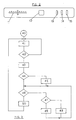
- FIG 3 that schematically represents a significant part of the logic flow of the control device of the refrigerator according to the invention (and in particular being relative to the thermostatic regulation of the refrigerating cell 6), with reference number 40 the starting block of the logic flow is indicated; such starting point for example, in the present case, could be that which occurs the first time that the refrigerator is put to use.
- Block 40 activates the compressor 10 and passes control to the successive block 41.
- Block 41 provides for setting to zero an internal clock and passes control to block 42.
- Block 42 is a test block, it verifies whether the temperature detected by the sensor 9 is inferior to that established by means of the manual regulator 11; in the positive case (YES output) control passes to the successive block 43; in the negative case (NO output) control passes back to block 41.
- the YES outputs are represented at the inferior part of the test block, while the NO outputs are represented laterally.
- Block 43 provides for deactivating the compressor 10; reads what is displayed on the clock and memorises it in an internal register; sets the clock to zero and passes the control to block 44.
- Block 44 is a test block that verifies whether the difference between the duration memorised in said internal register and that corresponding to the table contained in the ROM is minor to a pre-fixed value; in the positive case control passes to block 46; in the negative case control passes to block 45.
- Block 45 provides for activating the alarm signal, by flashing simultaneously the three luminous indicators and passes the control to block 46.
- Block 46 is a test block, it verifies on the clock whether a determined length of time has passed (for example 20 minutes) from the deactivation of the compressor 10; in the positive case control passes to block 50; in the negative case control passes to block 47.
- Block 47 is a test block, which verifies whether the temperature within the freezer cell is inferior to -18°C; in the positive case control passes to block 49; in the negative case control passes to block 48.
- Block 48 provides for deactivating the heating resistance 6a, in the case it is activated; control then passes back to block 46.
- Block 50 provides for activating the compressor 10 and passes the control back to block 41.
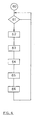
- block 60 represents the starting block of the function; block 60 passes control to the successive block 61.
- Block 61 is a test block, it verifies whether key 12 has been depressed for at least 5 seconds; in the positive case control passes to block 62; in the negative case control returns to block 61.
- Block 62 provides for lighting for a second the three luminous bars and passes the control to the successive block 63.
- Block 63 provides for reading in the third internal register the value of the activation/deactivation ratio of the compressor 10, to compare it with that indicated in the internal tables of the operative ROM, in correspondence of the value detected by the external sensor 5A and of that established by the manual regulator 11, and to read in the appropriate operative ROM table the failure code corresponding to the resulting difference; such code is memorised in a fourth internal register and the control is passed to the successive block 64.
- Block 64 provides for making the red indicator 13 carry out a given number of flashes corresponding to the first digit of the failure code contained within the fourth internal register; control then passes to block 66.
- Block 66 provides for making the yellow indicator 14 carry out a given number of flashes corresponding to the third digit of the failure code contained within the fourth internal register; control then passes back to block 61.
- the micro-controller is based on the indication of the external sensor, and uses the internal sensor as a control.
- the non volatile memory could be, at least in part, of the read and write type (EEPROM), thus enabling it to memorise functioning data (effective compressor activation/deactivation ratios), so as to be able to then communicate them upon request.
- EEPROM read and write type
- the display system of the failure codes could also be different from that indicated as an example.
Landscapes
- Engineering & Computer Science (AREA)
- Physics & Mathematics (AREA)
- Chemical & Material Sciences (AREA)
- Combustion & Propulsion (AREA)
- Mechanical Engineering (AREA)
- Thermal Sciences (AREA)
- General Engineering & Computer Science (AREA)
- General Physics & Mathematics (AREA)
- Automation & Control Theory (AREA)
- Devices That Are Associated With Refrigeration Equipment (AREA)
- Feedback Control In General (AREA)
Description
- The present invention relates to an electronically controlled electrical household appliance, in particular a refrigerator, according to the preamble of the annexed claim 1.
- Electrical household appliances of the type indicated are known, for instance all the modern domestic electronically controlled refrigerators normally comprise a first compartment destined to conserving fresh food and a second compartment destined to freezing and conserving food, a refrigerating circuit comprising a compressor, a first and a second evaporator, arranged respectively in said first and said second compartment, and a condenser; furthermore they are supplied with a temperature sensor in the first compartment (fresh food cell or fridge), in which a manual regulator for regulating the temperature to a preferred value is also supplied, within a field of acceptable values for conserving food; said sensor serves in deactivating the compressor when the temperature within the refrigerator cell has fallen below the value manually applied (+2° for example). It is also known to supply a second sensor to the evaporator of the first compartment, for detecting the instant of activation of the compressor (for example when the plate of the evaporator reaches the temperature of +4°).
- The difficulties are known of obtaining an acceptable control of the temperature be it either in the refrigerator cell or the freezer cell, in different environmental conditions that may occur (during the winter or the summer, in northern or southern countries, with the refrigerator in a heated house or situated on a balcony, etc. ).
- Moreover the temperature sensor or sensors are subject to alterations or differences of calibration, due to the inevitable production tolerances, for which it is easy to imagine the problems that may follow.
- Also other types of electrical household appliances, namely certain types of economic washing machines, that heat the water based on time, are influenced in a determining way by the external conditions, and in particular the temperature of the water, therefore during the summer they excessively heat the water, with a useless consumption of the electrical current, and during the winter there is the risk of washing at a temperature far too low, that may prejudice the washing effect. Also other types of electrical household appliances, namely cooking ovens, or hot water heaters (boilers), evidently are influenced by the external temperature, that affects their functioning.
- Even other external conditions, being different from the temperature, can sometimes decisively affect the functioning of electrical household appliances: consider for example dishwashers, of which the hardness of the water drawn is very influential.
- From GB-A-2.180.962 a refrigerator is also known, comprising a first compartment, a compressor that can be activated and deactivated, a temperature setting device for manually setting the desired temperature within said first compartment, an electronic digital control device that manages the functioning of the appliance, an external temperature sensor sensitive to the temperature prevailing outside the appliance and connected to said control device.
- An aim of the present invention is that to indicate an electrical household appliance, in which, with a relatively simple and inexpensive method, it is possible to take advantage of the electronic control for maintaining in an excellent way the operative conditions applied by means of the manual device.
- It is also an aim of the present invention to indicate how it is possible to guarantee acceptable results even in cases of alterations or failures of one of the components of the system; and to facilitate the identification of the abnormal functioning and the diagnosis of the present failure.
- In the particular case of a domestic refrigerator, the aim is to maintain, with minimum waste, within the compartment of the fresh food the temperature applied by means of the manual device, and to maintain within the freezer compartment a temperature inferior to that of -18°, in a field of external temperature ranging from +10° to +40°.
- In allowing for such aims the present invention has as its object an electronically controlled electrical household appliance, having the features of the annexed claim 1; further advantageous embodiments of the invention are then indicated in the
dependent claims 2 to 27. - Further aims and advantages of the present invention will become clear from the following detailed description and annexed drawings supplied as a non-limiting example, wherein:
- figure 1 schematically represents the refrigerator according to the invention;
- figure 2 schematically represents the command panel of the refrigerator of figure 1;
- figure 3 schematically represents a significant part of the logic flow of the control device of the refrigerator according to the invention;
- figure 4 schematically represents a further significant part of the logic flow of the control device of the refrigerator according to the invention.
- In figure 1, that schematically represents the refrigerator according to the invention, with
reference number 6 the first compartment (refrigerating cell) is indicated;reference number 4 indicates a second compartment (freezer cell); the reference number 1 indicates a motor ventilator;reference number 2 indicates the evaporator of the freezer compartment; the reference number 3 indicates a defrosting resistance, situated in the freezer compartment; thereference number 4a indicates a temperature sensor arranged in the freezer compartment. - The
reference number 5 indicates the command panel of the refrigerator, containing a part of the electronic control device of the functioning of the refrigerator, more precisely the so called "user interface", consisting of a stamped circuit card on which the following are welded (see figure 2): - a power-meter slider 11, that has the task of arranging for the desired temperature within the refrigerator compartment;
- a
key 12, that has the task of activating the fast freezing function; and - three luminous bars, a red one (13), that serves as an alarm signal, a green one (14) , that serves as a normal functioning indicator, and a yellow one (15°), that serves in signalling the activation of the fast freezing function.
- The three indicators also have the purpose of communicating, according to a special procedure, that will be described later, information on the operative conditions of the appliance.
- On the interface card, the external temperature sensor is also welded, indicated with the
reference number 5a; thereference number 5b indicates a nine wired cable that connects the interface cable with the second part of the control device, that is situated towards the bottom and is indicated with thereference number 7. - The
second part 7 of the control device (the actual control card) contains a supply circuit, a micro-controller and four power actuators and precisely three electromechanical relays, that have the purpose of controlling the activation/deactivation of the compressor (indicated with the reference number 10), of the freezer thawing resistance 3 and of the motor ventilator 1; and an optotriac, for example of the MOC3020, that has the purpose of controlling the activation/deactivation of a heating resistance, indicated with thereference number 6a, situated in the refrigerator compartment. - All of these actuators are controlled by the
device 7. - The
reference number 8b indicates the evaporator of the refrigerator compartment; the reference number 8 indicates a sensor that measures the temperature of the evaporator of the refrigerator compartment; thereference number 9 indicates a second sensor that measures the temperature of the air of the same compartment; both of the sensors are connected to thedevice 7 by means of thecable 8a. - In the figure 2, as mentioned above, an aspect of the command panel of the refrigerator is schematically represented, that presents a power meter slider 11 for the arranging of the temperature within the refrigerator compartment, a
key 12 for activating the fast freezing and three visual indicatingluminous bars - The functioning of the described refrigerator is the following. The micro-controller contained on the principle control card (7), by means of the sensor (9) of the air of the refrigerator cell (6) manages the thermostatic regulation of the refrigerator compartment, providing, through the appropriate relay, to deactivate the compressor (10) as soon as the temperature detected by the
sensor 9 reaches the inferior temperature value allowed, that is supplied by the user through the power meter slider 11, that allows for choosing between the 8 different levels of cold. - The same micro-controller then provides for activating the
compressor 10 as soon as a pre-fixed interval of time has passed (for example 20 minutes), from the deactivation; this system (fixed deactivation time) makes easier the control of the functioning ratio (ratio between activation time and total time), avoiding that the micro-controller carries out divisions. - Each time that the sum of activation times of the compressor reaches a determined value (for example 5 hours), a defrosting of the refrigerator compartment is carried out, i.e. the compressor is inactive until the temperature detected by the sensor (8), arranged on the evaporator of the refrigerator compartment, results in being equal to +4°C.
- The freezer compartment is of the "no frost" type, i.e. a ventilator is internally present (1) that circulates cold air coming from the
evaporator 2; in eliminating the ice accumulated on theevaporator 2, defrostings of the freezer are provided, that are effected by activating the resistance 3; a bimetal, not indicated in the figure, deactivates the resistance when the evaporator has reached a temperature sufficient in guaranteeing a total defrosting. - The interval between a defrosting of the freezer and a successive one is calculated with an appropriate algorithm, based on the duration of the last defrosting: the harder the defrosting the less the interval to the successive defrosting (system of the adaptive type). The micro-controller is associated to a non volatile digital memory, that can be a normal read only memory (ROM), in which its operative instructions are contained; in the same memory a series of tables are contained that place in relation the duration of the defrosting with the successive intervention.
- In a version of the refrigerator according to the invention the ROM memory also contains a table in which the optimal values of the reference parameters of the regulation, are contained in particular the optimum of the calibration threshold used for the thermostatic regulation of the refrigerator; in this version the value of the inferior temperature allowed in the refrigerator compartment is selected by the control system based on the value indicated by the user by means of the power meter slider 11, that allows for choosing between 8 different cold levels, and based on the value taken from external temperature. The micro controller carries out such dynamic corrections of the calibration of the
sensor 9 in function of the external temperature utilising experimental values contained in the table inserted in the non volatile memory. - With the aim of avoiding excessively long pauses, that could cause an excessive heating of the freezer, overlapping of a freezer defrosting with a defrosting of the refrigerator is prevented; in cases of overlapping, priority is given to the defrosting of the freezer; the defrosting of the refrigerator is carried out later as soon as the freezer has recuperated its coldness.
- In the presence of low external temperatures (less than 16°C), it can occur that the temperature in the
freezer cell 4, detected by thesensor 4a tends to increase over the limited pre-fixed temperature of -18°C; in such a case, the micro controller provides for activating theheating resistance 6a of therefrigerator cell 6 so as to re-establish the desired balance between the temperature in the two refrigerator and freezer cells and to maintain thecompressor 10 active until the temperature within the freezer cell descends to below the said limit. - The
resistance 6a is activated by means of theappropriate key 12. It is here to indicate that at the beginning of each rapid freeze a defrosting of the freezer is carried out; several seconds after depressing thekey 12, upon the beginning of the defrosting, the green led 14 starts to flash, to indicate that the system is about to arrange for generating the maximum cold; after that, the defrosting has terminated, the compressor will be continuously activated for a length of time sufficient for recuperating the coldness of the freezer (normally 45 minutes), the green led will stop flashing, to indicate that the freezing phase has effectively started. - The micro controller is informed of the external temperature by means of the
temperature sensor 5a welded to the interface card; in the ROM to which it is associated a series of tables are contained, that indicate, for all the steps of the external temperature values (detected by thesensor 5a), of four degrees in four degrees centigrade (in the field of temperature comprised between +9°C and +41°C), and for every position of the power-meter 11, the optimal of the functional ratio (activation/deactivation) of the compressor and the optimal value of the turning off temperature of the compressor detected by thesensor 9. - The tables are therefore eight (one for every step of the external temperature); each table indicates, in correspondence to the eight possible positions of the power-meter 11, the optimal value of activation time of the compressor (as mentioned above, as the deactivation time is fixed, it is not necessary to calculate the ratio and that of the turning off Temperature of the compressor); the values arranged in the tables are obtained by experimental surveys carried out on a sample of perfectly functional significant prototypes according to project specifications.
- In such a way the micro controller, has at its disposal more information than strictly necessary (external temperature), and has at its disposal information taken from experience (tables in ROM), it is able to carry out a dynamic correction of the temperature threshold of the turning off of the compressor in such a way that, upon varying external temperatures, the constant internal temperature of the refrigerator is always guaranteed, and moreover it is able to, by means of the knowledge of the optimal value of the functional ratio of the compressor to constantly verify whether everything is in order, and, in the contrary case, to carry out a diagnosis of the eventual abnormality, that could be due to for example the incorrect calibration of one or more sensors, or of other factors. In such circumstances, whenever the deviation exceeds a determined value, an automatic alarm indicator (for instance through use of flashing one or all three of the three luminous indicators) can be provided, so as to allow for a rapid intervention on behalf of the technical assistance before the situation becomes worse, or that damages occur.
- The diagnosis of failures is made possible by the fact that the ROM memory contains a series of numeric failure codes, each being associated to a combination of values of the deviation of the real functioning ratio with respect to those optimal and of the other parameters in play, such as the external temperature and the position of the manual regulation device 11.
- The failure code is accessible to the technician, or even to the user, that can communicate the code by telephone to the assistance service, thus facilitating the task.
- Keeping depressed for a determined period (for example 5 seconds) the rapid freeze key, an auto-diagnostic program is activated.
- Such a program lights for a second all three of the luminous bars, thus informing the user that the request for auto-diagnosis has been received; the failure code is then displayed, always by means of the three luminous bars, according to the following procedure: the three bars effect in sequence (first the red, then the green, then the yellow) a number of variable flashes from 1 to 3; in this way 27 different codes can be communicated (three digits in base 3), from 111 to 333, more than sufficient for describing the possible malfunctions of the system.
- With an analogous system the temperatures read by the four sensors can also be communicated: the
red bar 13 serves in indicating the temperature sign (on, negative sign; off, positive sign); thegreen bar 14 indicates, with its number of flashes, the number of tens; the yellow light indicates, with its number of flashes, the number of units. - For obtaining the temperature display a combination of operations is necessary, for example by depressing the key and simultaneously positioning the power-meter to the maximum position and then to the minimum; such combination is obviously reserved for technicians in the act of repairing.
- The system will then respond by flashing briefly all three of the luminous bars.
- For a major understanding a description of the behaviour of the
control device 7 will now be made with reference to figures 3 and 4. - In figure 3, that schematically represents a significant part of the logic flow of the control device of the refrigerator according to the invention (and in particular being relative to the thermostatic regulation of the refrigerating cell 6), with
reference number 40 the starting block of the logic flow is indicated; such starting point for example, in the present case, could be that which occurs the first time that the refrigerator is put to use. -
Block 40 activates thecompressor 10 and passes control to thesuccessive block 41. -
Block 41 provides for setting to zero an internal clock and passes control toblock 42. -
Block 42 is a test block, it verifies whether the temperature detected by thesensor 9 is inferior to that established by means of the manual regulator 11; in the positive case (YES output) control passes to thesuccessive block 43; in the negative case (NO output) control passes back toblock 41. In this, as in all the test blocks of the present figure and of figure 4, the YES outputs are represented at the inferior part of the test block, while the NO outputs are represented laterally. -
Block 43 provides for deactivating thecompressor 10; reads what is displayed on the clock and memorises it in an internal register; sets the clock to zero and passes the control toblock 44. -
Block 44 is a test block that verifies whether the difference between the duration memorised in said internal register and that corresponding to the table contained in the ROM is minor to a pre-fixed value; in the positive case control passes toblock 46; in the negative case control passes toblock 45. -
Block 45 provides for activating the alarm signal, by flashing simultaneously the three luminous indicators and passes the control toblock 46. -
Block 46 is a test block, it verifies on the clock whether a determined length of time has passed (for example 20 minutes) from the deactivation of thecompressor 10; in the positive case control passes toblock 50; in the negative case control passes toblock 47. -
Block 47 is a test block, which verifies whether the temperature within the freezer cell is inferior to -18°C; in the positive case control passes toblock 49; in the negative case control passes toblock 48. -
Block 48 provides for deactivating theheating resistance 6a, in the case it is activated; control then passes back to block 46. -
Block 50 provides for activating thecompressor 10 and passes the control back to block 41. - In figure 4, that schematically represents a further significant part of the logic flow of the control device of the refrigerator according to the invention, and in particular that being relative to the auto-diagnosis program, block 60 represents the starting block of the function; block 60 passes control to the
successive block 61. -
Block 61 is a test block, it verifies whether key 12 has been depressed for at least 5 seconds; in the positive case control passes to block 62; in the negative case control returns to block 61. -
Block 62 provides for lighting for a second the three luminous bars and passes the control to thesuccessive block 63. -
Block 63 provides for reading in the third internal register the value of the activation/deactivation ratio of thecompressor 10, to compare it with that indicated in the internal tables of the operative ROM, in correspondence of the value detected by the external sensor 5A and of that established by the manual regulator 11, and to read in the appropriate operative ROM table the failure code corresponding to the resulting difference; such code is memorised in a fourth internal register and the control is passed to thesuccessive block 64. -
Block 64 provides for making thered indicator 13 carry out a given number of flashes corresponding to the first digit of the failure code contained within the fourth internal register; control then passes to block 66. -
Block 66 provides for making theyellow indicator 14 carry out a given number of flashes corresponding to the third digit of the failure code contained within the fourth internal register; control then passes back to block 61. - The advantages of the electrical household appliance object of the present invention are, in particular, the following:
- the invariableness and stability of the temperature maintained in the refrigerator cell, corresponding to that manually established by the user;
- the maintaining of the temperature within the freezer cell constantly under -18°C, independently from the external temperature;
- control and assistance facilitated due to the advanced auto-diagnosis program contained in the ROM associated to the micro-controller;
- possibility of timely alarm indications, in the presence of abnormal functioning, otherwise not easily detectable by the user.
- It is clear that numerous variants are possible by the man skilled in the art, to the appliance described as an example.
- As an example it is cited that, instead of being based on the indication of the refrigerator air sensor for carrying out the thermostatic regulation, the micro-controller is based on the indication of the external sensor, and uses the internal sensor as a control.
- The non volatile memory could be, at least in part, of the read and write type (EEPROM), thus enabling it to memorise functioning data (effective compressor activation/deactivation ratios), so as to be able to then communicate them upon request.
- The display system of the failure codes could also be different from that indicated as an example.
Claims (27)
- Electronically controlled electrical household appliance, in particular a refrigerator, comprising a first compartment (6), a compressor (10) that can be activated and deactivated, a temperature setting device (11) for manually setting the desired temperature within said first compartment (6), an electronic digital control device (7) that manages the functioning of the appliance, an external temperature sensor (5a) sensitive to the temperature prevailing outside the appliance and connected to said control device (7), characterised by the fact that the control device (7) is associated to a non volatile memory (for example a ROM), in which tables are contained, indicating, for every position of the temperature setting device (11) and for every value supplied by the external sensor (5a) and comprised in a prefixed field of values (for instance +9°/+41°), the optimal value of the duration of activation of said compressor (10).
- Electrical household appliance, according to claim 1, characterised by the fact that said sensor (5a) is externally arranged regards the appliance.
- Electrical household appliance, according to claim 1 or 2, characterised by the fact that said control device (7) comprises circuitry means (44) for verifying whether the duration of activation of said compressor (10) is different, with respect to that being optimal indicated by said tables, of a quantity being greater than a pre-fixed one, and means (45) for activating, in the positive case, an alarm indication.
- Electrical household appliance, according to claim 3, characterised by the fact that said alarm indication is a luminous indication produced by a display device (13, 14, 15).
- Electrical household appliance, according to claim 1 or 2, characterised by the fact that said control device (7), in following a command externally received, provides in determining the difference between the effective duration of activation of said compressor (10) and the optimal one indicated by said tables, and to read a corresponding failure code contained in said non volatile memory.
- Electrical household appliance, according to claim 5, characterised by the fact that said control device (7) provides for displaying said failure code by means of display devices (13, 14, 15).
- Electrical household appliance, according to claim 6, characterised by the fact that each digit of said failure code is displayed by means of flashing, repeated a given number of times being equal to said digit, of a determined luminous device (13, 14, 15).
- Electrical household appliance, according to one or more of the previous claims, characterised by the fact that it is a refrigerator, in which said first compartment (6) is the compartment destined to conserve fresh food.
- Electrical household appliance, according to claim 8, characterised by the fact that it comprises also a second compartment (4) destined to the freezing and conserving of food, a first evaporator (8b) situated in said first compartment (6), a second evaporator (2) situated in said second compartment (4), a temperature sensor (9) for measuring the temperature relating to said first compartment (6), and a temperature sensor (8) for measuring the temperature of said first evaporator (8b).
- Electrical household appliance, according to claim 9, characterised by the fact that said refrigerator also comprises a treating resistance (6a) situated in said first compartment (6) and a temperature sensor (4a) situated in said second compartment (4).
- Electrical household appliance, according to claim 9, characterised by the fact that said control device (7) comprises circuitry means (42, 43) for deactivating said compressor (10) when the temperature detected by said temperature sensor (9) associated to said first compartment (6) is minor to or equal to the temperature established by the manual regulating device (11).
- Electrical household appliance, according to claim 11, characterised by the fact that said control device (7) comprises circuitry means (46, 50) for activating said compressor (10) when a period of time determined by its activation has passed.
- Electrical household appliance, according to claim 9, characterised by the fact that said control device (7) comprises circuitry means for activating said compressor (10) when the temperature detected by said sensor (8) associated to said first evaporator (8b) is minor to or equal to a pre-fixed temperature (for example +4°C).
- Electrical household appliance, according to claim 10, characterised by the fact that said control device (7) comprises circuitry means (47, 48) for activating said resistance (6a) when the temperature detected by said sensor (4a) associated to said second compartment (4) is major to or equal to a pre-fixed temperature (for example -18°C).
- Electrical household appliance, according to at least one of the previous claims, characterised by the fact that it comprises three functional luminous indicators, a red one (13), a green one (14) and a yellow one (15).
- Electrical household appliance, according to claim 3, characterised by the fact that said alarm indication is obtained by making three indicators of the refrigerator's functioning (13, 14, 15) flash simultaneously.
- Electrical household appliance, according to claim 5, characterised by the fact that each digit of said failure code is displayed through flashing, repeated a number of times being equal to said digit, of one of three indicators of the refrigerator's functioning (13, 14, 15).
- Electrical household appliance, according to at least one of the previous claims, characterised by the fact that said temperature setting device (11) comprises a power-meter of the linear type, otherwise called slider (11).
- Electrical household appliance, according to at least one of the previous claims, characterised by the fact that said control device (7) comprises a micro-controller.
- Electrical household appliance, according to claim 8, characterised by the fact that said control device (7) is provided for activating said compressor (10) based on the information supplied by said external sensor (5a) and on the tables contained in said non volatile memory, and for controlling whether the internal temperature of said first compartment (6) remains equal to or inferior to that established by means of said temperature setting device (11).
- Electrical household appliance, according to at least one of the previous claims, characterised by the fact that said non volatile memory, associated to said control device (7) is, at least in part, of the read write type (EEPROM), so as to be able to memorise functional data, and communicate it upon request.
- Electrical household appliance, according to at least one of the previous claims, characterised by the fact that it comprises a key (12) for commanding the beginning of a fast freezing phase and a luminous indicator (14).
- Electrical household appliance, according to claims 9 and 22, characterised by the fact that said fast freezing phase starts with a defrosting of the second compartment (4) and that said luminous indicator (14) starts to flash in concomitance with the beginning of said defrosting and passes to a steady light only upon termination of the defrosting and after that a determined interval of time has passed from the activation of said compressor (10), such interval being sufficient to allow said second compartment (4) to recuperate the normal level of cold.
- Electrical household appliance, according to claim 10, characterised in that it comprises- a refrigerating circuit comprising the compressor (10), the first (8b) and the second evaporator (2), respectively arranged in said first (6) and said second compartment (4), and a condenser,- said four temperature sensors (5a, 9, 8, 4a)whereby said control device (7) provides for continuously elaborating the information of the four sensors (9, 8, 4a, 5a) and of the manual regulating device (11), and acting on the activation times of said compressor (10) and of said heating element (6a), so as to maintain substantially stable and invariable the temperature of the first compartment (6), established by means of the manual regulating device (11), independently from the external temperature value, and to simultaneously maintain in the second compartment (4) a temperature being inferior to a pre-fixed temperature value (for example -18° C).
- Electrical household appliance, according to claim 1, characterised by the fact that, in said non volatile memory, there are also contained tables indicating the optimal value of the reference parameters of the temperature regulation.
- Electrical household appliance, according to claim 25, characterised by the fact that said reference parameters of the regulation comprise the calibration threshold used for the thermostatic regulation of the refrigerator.
- Electrical household appliance, according to claims 19 and 26, characterised by the fact that the micro-controller is apt at carrying out a dynamic correction of the temperature threshold for turning off the compressor so as that, upon variations of the external temperature, a constant internal temperature of the refrigerator is always guaranteed.
Applications Claiming Priority (2)
| Application Number | Priority Date | Filing Date | Title |
|---|---|---|---|
| ITTO910295A IT1248098B (en) | 1991-04-18 | 1991-04-18 | ELECTRONICALLY CONTROLLED HOUSEHOLD APPLIANCE, IN PARTICULAR A REFRIGERATOR |
| ITTO910295 | 1991-04-18 |
Publications (3)
| Publication Number | Publication Date |
|---|---|
| EP0513539A2 EP0513539A2 (en) | 1992-11-19 |
| EP0513539A3 EP0513539A3 (en) | 1993-12-01 |
| EP0513539B1 true EP0513539B1 (en) | 1996-04-03 |
Family
ID=11409266
Family Applications (1)
| Application Number | Title | Priority Date | Filing Date |
|---|---|---|---|
| EP92106516A Expired - Lifetime EP0513539B1 (en) | 1991-04-18 | 1992-04-15 | Household appliance with electronic control |
Country Status (4)
| Country | Link |
|---|---|
| EP (1) | EP0513539B1 (en) |
| DE (1) | DE69209559T2 (en) |
| ES (1) | ES2086020T3 (en) |
| IT (1) | IT1248098B (en) |
Families Citing this family (13)
| Publication number | Priority date | Publication date | Assignee | Title |
|---|---|---|---|---|
| BR9300953A (en) * | 1993-04-14 | 1994-11-22 | Brasil Compressores Sa | Control circuit for cooling system |
| IT1266851B1 (en) * | 1994-06-08 | 1997-01-21 | Merloni Elettrodomestici Spa | METHOD FOR THE CONTROL OF A REFRIGERATOR, AND THE IMPLEMENTING APPARATUS THIS METHOD |
| EP0984232B1 (en) * | 1994-11-11 | 2002-12-18 | Samsung Electronics Co., Ltd. | Control method of a refrigerator having high efficiency multi-evaporator cycle (h.m.cycle) |
| KR0146100B1 (en) * | 1995-01-07 | 1998-09-15 | 이헌조 | Information acquisition and analysis device |
| DE19505706A1 (en) * | 1995-02-20 | 1996-08-22 | Aeg Hausgeraete Gmbh | Control device and method for temperature control in cooling devices |
| DE10064318A1 (en) * | 2000-12-22 | 2002-07-04 | Bsh Bosch Siemens Hausgeraete | Method for controlling a cooling device |
| US8136365B2 (en) * | 2007-07-02 | 2012-03-20 | Hoshizaki Denki Kabushiki Kaisha | Cooling apparatus having a variable speed compressor with speed limited on the basis of a sensed performance parameter |
| EP2048460A1 (en) * | 2007-10-11 | 2009-04-15 | Nico Technology Ltd. | Refrigeration control device to reduce power consumption of a refrigeration appliance |
| DE202007017690U1 (en) * | 2007-10-26 | 2009-03-19 | Liebherr-Hausgeräte Lienz Gmbh | Fridge and / or freezer |
| DE202008012411U1 (en) * | 2008-08-14 | 2009-12-17 | Liebherr-Hausgeräte Ochsenhausen GmbH | Fridge and / or freezer |
| DE102017223226A1 (en) * | 2017-12-19 | 2019-06-19 | Henkel Ag & Co. Kgaa | Use of external information when operating a household appliance |
| CN108681267B (en) * | 2018-05-23 | 2021-08-03 | 九阳股份有限公司 | Control method and device for household appliance |
| CN111692798A (en) * | 2019-03-11 | 2020-09-22 | 青岛海尔电冰箱有限公司 | Air-cooled refrigerator |
Family Cites Families (9)
| Publication number | Priority date | Publication date | Assignee | Title |
|---|---|---|---|---|
| DE1949970A1 (en) * | 1969-10-03 | 1971-04-29 | May And Robertson Stevenage Lt | Temperature alarm circuit for refrigerating - plant |
| GB1545594A (en) * | 1977-09-07 | 1979-05-10 | Fogden & Co Ltd M | Temperature monitoring |
| US4364234A (en) * | 1981-03-25 | 1982-12-21 | Koolatron Industries, Ltd. | Control circuitry for thermoelectric environmental chamber |
| EP0120490A3 (en) * | 1983-03-28 | 1985-07-10 | Honeywell Inc. | Defrost control system |
| CN1010883B (en) * | 1985-09-25 | 1990-12-19 | 三菱电机株式会社 | Refrigerator Controls |
| IT1220060B (en) * | 1987-07-09 | 1990-06-06 | Zanussi A Spa Industrie | MULTI-TEMPERATURE REFRIGERANT APPLIANCE WITH SINGLE-COMPRESSOR REFRIGERANT CIRCUIT AND SINGLE THERMOSTATIC TEMPERATURE REGULATION |
| DE3837629A1 (en) * | 1988-11-05 | 1990-05-17 | Erwin Dietz | Method for monitoring electrical cooling appliances, especially refrigerators or freezers |
| IT1232574B (en) * | 1989-02-13 | 1992-02-26 | Merloni Elettrodomestici Spa | REFRIGERATED REFRIGERATOR |
| IT1233203B (en) * | 1989-04-14 | 1992-03-20 | Merloni Elettrodomestici Spa | REFRIGERATED REFRIGERATOR |
-
1991
- 1991-04-18 IT ITTO910295A patent/IT1248098B/en active IP Right Grant
-
1992
- 1992-04-15 DE DE69209559T patent/DE69209559T2/en not_active Expired - Fee Related
- 1992-04-15 EP EP92106516A patent/EP0513539B1/en not_active Expired - Lifetime
- 1992-04-15 ES ES92106516T patent/ES2086020T3/en not_active Expired - Lifetime
Also Published As
| Publication number | Publication date |
|---|---|
| ITTO910295A1 (en) | 1992-10-18 |
| EP0513539A3 (en) | 1993-12-01 |
| ES2086020T3 (en) | 1996-06-16 |
| DE69209559T2 (en) | 1996-09-26 |
| EP0513539A2 (en) | 1992-11-19 |
| DE69209559D1 (en) | 1996-05-09 |
| IT1248098B (en) | 1995-01-05 |
| ITTO910295A0 (en) | 1991-04-18 |
Similar Documents
| Publication | Publication Date | Title |
|---|---|---|
| US5634346A (en) | Apparatus and method for controlling a room air conditioner | |
| EP0513539A2 (en) | Household appliance with electronic control | |
| US4940079A (en) | Optimal control system for refrigeration-coupled thermal energy storage | |
| US4297852A (en) | Refrigerator defrost control with control of time interval between defrost cycles | |
| US4156350A (en) | Refrigeration apparatus demand defrost control system and method | |
| US4993233A (en) | Demand defrost controller for refrigerated display cases | |
| US4283921A (en) | Control and alarm system for freezer case temperature | |
| CA1129037A (en) | Refrigeration system control method and apparatus | |
| US4173871A (en) | Refrigeration apparatus demand defrost control system and method | |
| US4879878A (en) | Air damper assembly for refrigerator/freezer | |
| CN110701866B (en) | Defrosting control method of refrigerator and refrigerator | |
| US4228846A (en) | Control apparatus for a two-speed heat pump | |
| US8091375B2 (en) | Humidity control for air conditioning system | |
| JPS62206370A (en) | Refrigeration control system capable of self-adjusting interval of defrostation | |
| EP0686818B1 (en) | Control method for a refrigerator apparatus and an apparatus implementing such method | |
| US5156010A (en) | Defrost control method for a heat pump | |
| MXPA97005885A (en) | Control apparatus for espa cooling system | |
| US4615179A (en) | Defrost diagnostic arrangement for self-defrosting refrigerator appliance | |
| US4142374A (en) | Demand defrost time clock control circuit | |
| CA2348199C (en) | Self-optimizing device for controlling a heating system | |
| GB2201498A (en) | Refrigerator with defrost override system | |
| US4206612A (en) | Refrigeration system control method and apparatus | |
| US4392358A (en) | Apparatus and method of detecting failure in a refrigerator defrost system | |
| EP0383222B1 (en) | Refrigerating device | |
| EP0204521B1 (en) | A heating and/or cooling system |
Legal Events
| Date | Code | Title | Description |
|---|---|---|---|
| PUAI | Public reference made under article 153(3) epc to a published international application that has entered the european phase |
Free format text: ORIGINAL CODE: 0009012 |
|
| AK | Designated contracting states |
Kind code of ref document: A2 Designated state(s): DE ES FR GB IT PT |
|
| PUAL | Search report despatched |
Free format text: ORIGINAL CODE: 0009013 |
|
| AK | Designated contracting states |
Kind code of ref document: A3 Designated state(s): DE ES FR GB IT PT |
|
| 17P | Request for examination filed |
Effective date: 19940427 |
|
| 17Q | First examination report despatched |
Effective date: 19950210 |
|
| GRAA | (expected) grant |
Free format text: ORIGINAL CODE: 0009210 |
|
| GRAH | Despatch of communication of intention to grant a patent |
Free format text: ORIGINAL CODE: EPIDOS IGRA |
|
| AK | Designated contracting states |
Kind code of ref document: B1 Designated state(s): DE ES FR GB IT PT |
|
| PG25 | Lapsed in a contracting state [announced via postgrant information from national office to epo] |
Ref country code: IT Free format text: LAPSE BECAUSE OF FAILURE TO SUBMIT A TRANSLATION OF THE DESCRIPTION OR TO PAY THE FEE WITHIN THE PRE;WARNING: LAPSES OF ITALIAN PATENTS WITH EFFECTIVE DATE BEFORE 2007 MAY HAVE OCCURRED AT ANY TIME BEFORE 2007. THE CORRECT EFFECTIVE DATE MAY BE DIFFERENT FROM THE ONE RECORDED.SCRIBED TIME-LIMIT Effective date: 19960403 |
|
| REF | Corresponds to: |
Ref document number: 69209559 Country of ref document: DE Date of ref document: 19960509 |
|
| REG | Reference to a national code |
Ref country code: ES Ref legal event code: FG2A Ref document number: 2086020 Country of ref document: ES Kind code of ref document: T3 |
|
| ET | Fr: translation filed | ||
| SC4A | Pt: translation is available |
Free format text: 960527 AVAILABILITY OF NATIONAL TRANSLATION |
|
| PLBE | No opposition filed within time limit |
Free format text: ORIGINAL CODE: 0009261 |
|
| STAA | Information on the status of an ep patent application or granted ep patent |
Free format text: STATUS: NO OPPOSITION FILED WITHIN TIME LIMIT |
|
| 26N | No opposition filed | ||
| REG | Reference to a national code |
Ref country code: GB Ref legal event code: IF02 |
|
| PGFP | Annual fee paid to national office [announced via postgrant information from national office to epo] |
Ref country code: FR Payment date: 20030428 Year of fee payment: 12 |
|
| PGFP | Annual fee paid to national office [announced via postgrant information from national office to epo] |
Ref country code: GB Payment date: 20030502 Year of fee payment: 12 |
|
| PGFP | Annual fee paid to national office [announced via postgrant information from national office to epo] |
Ref country code: DE Payment date: 20030505 Year of fee payment: 12 Ref country code: PT Payment date: 20030505 Year of fee payment: 12 |
|
| PGFP | Annual fee paid to national office [announced via postgrant information from national office to epo] |
Ref country code: ES Payment date: 20030509 Year of fee payment: 12 |
|
| PG25 | Lapsed in a contracting state [announced via postgrant information from national office to epo] |
Ref country code: GB Free format text: LAPSE BECAUSE OF NON-PAYMENT OF DUE FEES Effective date: 20040415 |
|
| PG25 | Lapsed in a contracting state [announced via postgrant information from national office to epo] |
Ref country code: ES Free format text: LAPSE BECAUSE OF NON-PAYMENT OF DUE FEES Effective date: 20040416 |
|
| PG25 | Lapsed in a contracting state [announced via postgrant information from national office to epo] |
Ref country code: PT Free format text: LAPSE BECAUSE OF NON-PAYMENT OF DUE FEES Effective date: 20041015 |
|
| PG25 | Lapsed in a contracting state [announced via postgrant information from national office to epo] |
Ref country code: DE Free format text: LAPSE BECAUSE OF NON-PAYMENT OF DUE FEES Effective date: 20041103 |
|
| GBPC | Gb: european patent ceased through non-payment of renewal fee |
Effective date: 20040415 |
|
| PG25 | Lapsed in a contracting state [announced via postgrant information from national office to epo] |
Ref country code: FR Free format text: LAPSE BECAUSE OF NON-PAYMENT OF DUE FEES Effective date: 20041231 |
|
| REG | Reference to a national code |
Ref country code: FR Ref legal event code: ST |
|
| REG | Reference to a national code |
Ref country code: ES Ref legal event code: FD2A Effective date: 20040416 |