EP0513509A1 - Elevator - Google Patents
Elevator Download PDFInfo
- Publication number
- EP0513509A1 EP0513509A1 EP92105573A EP92105573A EP0513509A1 EP 0513509 A1 EP0513509 A1 EP 0513509A1 EP 92105573 A EP92105573 A EP 92105573A EP 92105573 A EP92105573 A EP 92105573A EP 0513509 A1 EP0513509 A1 EP 0513509A1
- Authority
- EP
- European Patent Office
- Prior art keywords
- door
- car
- control cam
- pull rod
- drive device
- Prior art date
- Legal status (The legal status is an assumption and is not a legal conclusion. Google has not performed a legal analysis and makes no representation as to the accuracy of the status listed.)
- Granted
Links
Images


Classifications
-
- B—PERFORMING OPERATIONS; TRANSPORTING
- B66—HOISTING; LIFTING; HAULING
- B66B—ELEVATORS; ESCALATORS OR MOVING WALKWAYS
- B66B13/00—Doors, gates, or other apparatus controlling access to, or exit from, cages or lift well landings
-
- B—PERFORMING OPERATIONS; TRANSPORTING
- B66—HOISTING; LIFTING; HAULING
- B66B—ELEVATORS; ESCALATORS OR MOVING WALKWAYS
- B66B13/00—Doors, gates, or other apparatus controlling access to, or exit from, cages or lift well landings
- B66B13/02—Door or gate operation
- B66B13/12—Arrangements for effecting simultaneous opening or closing of cage and landing doors
Definitions
- the present invention relates to a door drive device with a locking mechanism for lifts, in which a car door, which can be connected to a shaft door by a coupling mechanism, can be moved by a door drive in the area of the floors, the coupling mechanism comprising a driver parallelogram mounted on a car door leaf and two coupling rollers each arranged on each shaft door there is and the door drive has a drive motor arranged above the cabin, a countershaft and a band-shaped drive means which is connected to the cabin door by an actuating member and fixes the cabin door in the closed and in the open position and the locking mechanism a pivotally mounted monitored by a safety contact has a lockable car door latch at a stop, which locks in a holding position due to its own weight and into a release by an actuating device position can be pressed.
- the coupling mechanism comprising a driver parallelogram mounted on a car door leaf and two coupling rollers each arranged on each shaft door there is and the door drive has a drive motor arranged above the cabin, a
- EP-PS 0 164 581 has disclosed such a door drive device with a locking mechanism for elevators, in which, for coupling the cabin door to a landing door, a driver parallelogram arranged on the cabin door cooperates with two roller journals fastened to each landing door.
- a pawl controlled by the driver parallelogram and an angle lever holds the cabin door in a locked position, on the one hand when the driver parallelogram is closed for free passage through an uncontrolled floor and on the other hand when the driver parallelogram is fully open, for example, in the event of a power failure, outside a floor.
- the pawl is opened when the cabin is in the area of a floor, in that a control roller arranged on the angle lever runs onto a control curve arranged on the shaft door and rotates the angle lever, the pawl being guided out of the lock.
- This unlocking takes place on each controlled floor, or in the event of a power failure when the elevator car is located within the door opening zone of a floor.
- the cabin door and the coupled shaft door are either opened automatically by the door operator or can be pushed open by hand.
- the car door remains locked when the elevator car is outside the door opening zone on one floor, for example in the event of a power failure.
- a disadvantage of this device is that a control curve is required for unlocking the cabin door lock on each floor, which cam must cooperate precisely with the drive device arranged on the cabin on each floor and therefore requires precise and complex regulation work on the construction site.
- FIG. 1 Another door drive device with a locking mechanism for elevators of a similar design has become known from EP-A-0 332 841.
- the cabin door in the area of the floors can also be connected to the shaft door by means of a coupling mechanism, a driver parallelogram arranged on a cabin door wing and two clutch rollers arranged on a shaft door wing in turn working together.
- the closed driver parallelogram travels between the clutch rollers of a shaft door when it is free to move, on a target floor it couples to the clutch rollers by opening the driver parallelogram.
- the driver parallelogram is normally closed through the door drive device, wherein an actuating lever pivotally connected to a band-shaped drive means of the door drive device and the driver parallelogram and pivotable back and forth between two firmly placed elastic stops closes the driver parallelogram by a pivoting movement in the counterclockwise direction.
- the opening of the driver parallelogram is carried out by the force of a tension spring acting on the actuating lever and on the base plate of the driver parallelogram, either when the drive motor is currentless or when the drive motor controlled by a microprocessor is switched in the opening direction.
- the driver parallelogram is held in a central position by the coupling rollers of the shaft door, in which a run-up curve of the driver parallelogram is compressed in parallel and a control curve arranged on the run-up curve unlocks the car door lock.
- the driver parallelogram is locked in this central position by an additional locking device.
- a disadvantage of this device is that a faultless and expensive control for the door drive motor is required for proper door operation, that the driver parallelogram and the car door lock are spatially arranged and that the door drive device can only be used to a limited extent if shaft heights of different heights are operated on the same elevator and that for the opening movement of the doors with the door drive device, an additional locking for the open driver parallelogram is required.
- the invention is based on the object of proposing a door drive device in which there are no control cams for unlocking the individual shaft doors the cabin door locking must be arranged, and which places lower quality demands on the door motor control and regulation and which does not require any additional locking for the driver parallelogram.
- Another advantage is that the actuation of the driver parallelogram and the start of the door movement by means of a control curve and a toggle lever enable the driver parallelogram and the door to be opened and closed smoothly on the closing side.
- the door motor control and regulation of comparatively similar door drives can thus be considerably simplified and made cheaper.
- FIG. 1 denotes a door drive of an elevator system.
- the door drive 1 consists of a drive motor 2 , a countershaft 3 , a drive belt 4 , a drive roller 5 , a tensionable deflection roller 6 and a belt-shaped drive means 7 .
- the door drive 1 is constructed over a door opening 8 on a sheet metal support 9 arranged on the roof of an elevator car.
- Guide rails 10.1, 10.2, 10.3 are also arranged on the same sheet metal support 9 , for receiving sliding carriages 11.1, 11.2, 11.3, each of which carries a single door leaf 12.1, 12.2, 12.3 .
- the first push carriage 11.1 is connected in an articulated manner to the band-shaped drive means 7 by means of a clamping element 13 , via a toggle lever 14 and a control cam 15 .
- This connection is shown more clearly in FIGS. 4 and 5, on a larger scale.
- the two other sliding carriages 11.2, 11.3 are connected to each other and to the first sliding carriage 11.1 by means of cables 16, 17 known per se for taking them along.
- the position of a arranged on the first sliding carriage 11.1 entraining 18 and a pivotally mounted cage door latch 46, and a fixed and a movable coupling part 19, 20 of the respective landing door is dash-dottedrios.
- Das clamping member 13 on a arranged on the first sliding carriage 11.1 slideway 21 within a of limited path.
- the control cam 15 is also rotatably mounted on the first sliding carriage 11.1 of the first door leaf 12.1 on an axis of rotation 22 of a holding plate 23 and projects with a pivot pin 24 into a recess 25 in a holding plate 23 . It is from the door drive 1 on the band-shaped Drive means 7 held in a closed position by a tensile force 54 (FIG. 4) and pulled into an open position by a tension spring 26 (FIG. 5).
- a roller 27 arranged on the sheet metal carrier 9 serves as a rolling roller for the contour of the control cam 15 .
- the driver parallelogram 18 is arranged on a support plate 28 on the first sliding carriage 11.1 . It consists of two curves 29, 30 which are articulated to an upper 31 and a lower lever 32 , which in turn are rotatably mounted on pivot pins 33, 34 of the support plate 28 .
- a pull rod 36 is articulated on an axis 35 , which connects the driver parallelogram 18 to the control curve 15 .
- the pull rod 36 is equipped with a length compensation 37 and has a stop 38 for a double lever 39 and a run-up curve 40 for a support roller 41 fixedly arranged on the sheet metal support 23 .
- the double lever 39 is articulated at one end with a pin 42 to the pull rod 36 and rests with the central pivot bearing on the axis 24 of the control cam 15 protruding into the recess 25 of the holding plate 23 .
- the force of a tension spring 43 pulls the double lever 39 in a rest position against the stop 38 of the pull rod 36 .
- An elastic buffer 44 is provided on the axis 24 of the control cam 15 in order to dampen the opening movement of the control cam 15 at the end of the recess 25 .
- a pivot pin 45 is provided, on which a cabin door latch 46 is pivotally mounted.
- an actuating tab 47 is articulated, the other end of which has an actuating roller 49 guided in a link 48 of the holding plate 23 .
- a locking roller 50 and a contact bridge 51 are arranged on the rear part of the car door latch 46 , which cooperate with a locking curve 52 fastened to the sheet metal support 9 of the elevator car and an electrical safety contact 53 which monitors the locked position of the car door lock.
- three-wing telescopic sliding door consists of three door leaves 12.1, 12.2, 12.3 , which are attached to three sliding carriages 11.1, 11.2, 11.3 running on parallel guide rails 10.1, 10.2, 10.3 .
- the drive means 7 of the door drive 1 is connected to the door leaf 12.1 , which has to cover the greatest distance for opening or closing the door opening 8 .
- the other two door leaves 12.2, 12.3 are indirectly driven by cables 16, 17 , known per se, in such a way that the middle door leaf 12.2 , 2/3 and the third door leaf 12.3 , 1/3 simultaneously cover the path of the directly driven door leaf 12.1 and, for example, when the car door is open, all three door leaves 12.1, 12.2, 12.3 simultaneously lie exactly one behind the other outside the car door opening. In the closed state, the three door leaves 12.1, 12.2, 12.3 are staggered one behind the other and cover the door opening 8 entirely.
- the switched-on car door drive 1 acts via the band-shaped drive means 7 with the tensile force 54 on the driven door leaf 12.1 and brings the car sliding door into the two positions.
- the function of the door drive device, the driver parallelogram and the locking mechanism are to keep the cabin door locked while the cabin is moving, to unlock and couple the cabin door and the landing door on a target floor so that the landing door opens and closes together with the cabin door operated by the door drive device and both doors again before continuing to lock.
- the regulations must be met that, in the event of a power failure, the cabin door must remain locked outside the door opening area of a floor, or in the door opening area of the floor, the cabin door and the corresponding landing door must be unlocked automatically so that both doors can be opened by an enclosed passenger by hand .
- a safety contact (not shown) monitors the locking of the landing door electrically.
- the pivotably mounted car door latch 46 is guided with its locking roller 50 over the locking curve 52 , the car door is locked and the electrical safety contact 53 is closed by the contact bridge 51 . In this state, the elevator car is ready to continue.
- the door drive device 1 is switched over, the tensile force 54 on the belt-shaped drive means 7 changing its direction (see FIGS. 5, 6 and 9).
- the clamping element 13 becomes along the sliding guide 21 wherein the control cam 15 is rotated via the toggle lever 14 about the axis of rotation 22 and the contour of the cam 15 rolls on the fixed plate on the carrier 9 roller 27 pulled in inside direction.
- the contour of the control curve 15 is designed such that a jerk-free opening and closing of the driver parallelogram 18 and the doors on the closing side is ensured.
- the control cam rotates until the elastic buffer 44 abuts the axis 24 projecting into the recess 25 of the holding plate 23 at the end of the recess 25 .
- the driver parallelogram 18 opens, actuated by the pull rod 36 connected to the control cam 15 via the double lever 39 , until the two curves 29, 30 of the driver parallelogram 18 are present on the fixed and on the movable coupling roller 19, 20 of the shaft door present .
- the movable clutch roller 20 is pushed away by a certain distance and thereby unlocks the landing door.
- the parallel parallelogram 18 assumes the middle position indicated by dash-dotted lines in FIG.
- the shaft door lock and the car door lock are unlocked in the same manner as shown above, with the exception that the tractive force 54 , which acts on the control curve 15 from the door drive 1 , the force of the tension spring 26 occurs, which rotates the control cam 15 , the clamping element 13 with the moves band-shaped drive means 7 in the slide guide 21 , the driver parallelogram 18 opens and unlocks the shaft door lock and the cabin door lock.
- a possibly enclosed passenger then has the option of opening the cabin door and the coupled landing door together by hand.
- the driver parallelogram 18 opens to a maximum, with the pull rod 36 occupying the highest position at which the double lever 39 is pressed up about the axis 24 on the pull rod side and pressed down on the unlocking side.
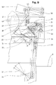
- the actuating roller 49 of the car door latch 46 is not moved and the car door lock remains locked. Any trapped passenger cannot open the cabin door by hand (see Fig. 8).
- FIGS. 1, 2 and 3 a telescopic sliding door with three door leaves is shown. It is readily possible to equip any other type of sliding door with the door drive device according to the invention, for example also a centrally opening telescopic sliding door.
- a belt-shaped drive means for transmitting the opening and closing movements, from the door drive to the door leaf
- another drive means for example a push crank drive, could also be provided.
Abstract
Description
Die vorliegende Erfindung betrifft eine Türantriebsvorrichtung mit Verriegelungsmechanismus für Aufzüge, bei welcher im Bereich der Etagen eine mit einer Schachttür durch einen Kupplungsmechanismus verbindbare Kabinentür Von einem Türantrieb bewegbar ist, wobei der Kupplungsmechanismus aus einem an einem Kabinentürflügel gelagerten Mitnehmerparallelogramm und zwei jeweils an jeder Schachttür angeordneten Kupplungsrollen besteht und der Türantrieb ein über der Kabine angeordneter Antriebsmotor, ein Vorgelege und ein bandförmiges Antriebsmittel aufweist, welches mit der Kabinentür durch ein Betätigungsorgan verbunden ist und die Kabinentür in der geschlossenen und in der offenen Stellung fixiert und der Verriegelungsmechanismus einen durch einen Sicherheitskontakt überwachten schwenkbar gelagerten an einem Anschlag arretierbaren Kabinentürriegel aufweist, welcher durch das Eigengewicht in einer Haltestellung verriegelt und durch eine Betätigungseinrichtung in eine Freigabestellung drückbar ist.The present invention relates to a door drive device with a locking mechanism for lifts, in which a car door, which can be connected to a shaft door by a coupling mechanism, can be moved by a door drive in the area of the floors, the coupling mechanism comprising a driver parallelogram mounted on a car door leaf and two coupling rollers each arranged on each shaft door there is and the door drive has a drive motor arranged above the cabin, a countershaft and a band-shaped drive means which is connected to the cabin door by an actuating member and fixes the cabin door in the closed and in the open position and the locking mechanism a pivotally mounted monitored by a safety contact has a lockable car door latch at a stop, which locks in a holding position due to its own weight and into a release by an actuating device position can be pressed.
Mit der EP-PS 0 164 581 ist eine derartige Türantriebsvorrichtung mit Verriegelngsmachanismus für Aufzüge bekanntgeworden, bei welcher für das Ankuppeln der Kabinentür mit einer Schachttür ein an der Kabinentür angeordnetes Mitnehmerparallelogramm mit zwei jeweils an jeder Schachttür befestigten Rollenzapfen zusammenarbeitet. Eine durch das Mitnehmerparallelogramm und einen Winkelhebel gesteuerte Klinke hält die Kabinentür in einer verriegelten Stellung, einerseits bei geschlossenem Mitnehmerparallelogramm für die freie Durchfahrt durch eine nicht angesteuerte Etage und anderseits bei ganz geöffnetem Mitnehmerparallelogramm, beispielsweise bei Stromausfall, ausserhalb eines Stockwerkes. Die Klinke wird geöffnet, wenn sich die Kabine im Bereich einer Etage befindet, indem eine am Winkelhebel angeordnete Steuerrolle auf eine an der Schachttür angeordnete Steuerkurve aufläuft und den Winkelhebel dreht, wobei die Klinke aus der Verriegelung geführt wird. Diese Entriegelung erfolgt in jeder angesteuerten Etage, oder bei Stromausfall dann, wenn sich die Aufzugskabine innerhalb der Türöffnungszone einer Etage befindet. Die Kabinentür und die angekuppelte Schachttür werden, je nach dem Zustand, entweder durch den Türantrieb automatisch geöffnet, oder können von Hand aufgedrückt werden. Die Kabinentür bleibt aber verriegelt, wenn sich die Aufzugskabine, beispielsweise bei Stromausfall, ausserhalb der Türöffnungszone einer Etage befindet.EP-PS 0 164 581 has disclosed such a door drive device with a locking mechanism for elevators, in which, for coupling the cabin door to a landing door, a driver parallelogram arranged on the cabin door cooperates with two roller journals fastened to each landing door. A pawl controlled by the driver parallelogram and an angle lever holds the cabin door in a locked position, on the one hand when the driver parallelogram is closed for free passage through an uncontrolled floor and on the other hand when the driver parallelogram is fully open, for example, in the event of a power failure, outside a floor. The pawl is opened when the cabin is in the area of a floor, in that a control roller arranged on the angle lever runs onto a control curve arranged on the shaft door and rotates the angle lever, the pawl being guided out of the lock. This unlocking takes place on each controlled floor, or in the event of a power failure when the elevator car is located within the door opening zone of a floor. Depending on the condition, the cabin door and the coupled shaft door are either opened automatically by the door operator or can be pushed open by hand. However, the car door remains locked when the elevator car is outside the door opening zone on one floor, for example in the event of a power failure.
Ein Nachteil dieser Vorrichtung liegt darin, dass in jeder Etage eine Steuerkurve für die Entriegelung der Kabinentürverriegelung erforderlich ist, welche in jeder Etage genau mit der an der Kabine angeordneten Antriebsvorrichtung zusammenarbeiten muss und deshalb auf der Baustelle genaue und aufwendige Regulierarbeiten erfordert.A disadvantage of this device is that a control curve is required for unlocking the cabin door lock on each floor, which cam must cooperate precisely with the drive device arranged on the cabin on each floor and therefore requires precise and complex regulation work on the construction site.
Eine weitere Türantriebsvorrichtung mit Verriegelungsmechanismus für Aufzüge ähnlicher Bauart ist mit der EP-A-0 332 841 bekanntgeworden. Bei dieser Vorrichtung ist die Kabinentür im Bereich der Etagen ebenfalls durch einen Kupplungsmechanismus mit der Schachttür verbindbar, wobei wiederum ein an einem Kabinentürflügel angeordnetes Mitnehmerparallelogramm und jeweils zwei an einem Schachttürflügel angeordnete Kupplungsrollen zusammenarbeiten. Das geschlossene Mitnehmerparallelogramm fährt bei freier Fahrt zwischen den Kupplungsrollen einer Schachttür hindurch, in einer Zieletage kuppelt es durch das Öffnen des Mitnehmerparallelogrammes an den Kupplungsrollen an. Das Schliessen des Mitnehmerparallelogrammes erfolgt im Normalfall durch die Türantriebsvorrichtung, wobei ein gelenkig mit einem bandförmigen Antriebsmittel der Türantriebsvorrichtung und dem Mitnehmerparallelogramm verbundener, zwischen zwei fest plazierten elastischen Anschlägen hin- und herschwenkbarer Betätigungshebel das Mitnehmerparallelogramm durch eine Schwenkbewegung im Gegenuhrzeigersinn schliesst. Das Öffnen des Mitnehmerparallelogrammes wird durch die Kraft einer am Betätigungshebel und an der Grundplatte des Mitnehmerparallelogrammes angreifenden Zugfeder ausgeführt, entweder bei stromlosem Antriebsmotor oder beim Umschalten des durch einen Mikroprozessor geregelten Antriebsmotors in die Öffnungsrichtung. Erfolgt diese Öffnung innerhalb der Türöffnungszone einer Etage, wird das Mitnehmerparallelogramm durch die Kupplungsrollen der Schachttür in einer Mittellage gehalten, bei welcher eine Auflaufkurve des Mitnehmerparallelogrammes parallel zusammengedrückt wird und dabei eine an der Auflaufkurve angeordnete Steuerkurve die Kabinentürverriegelung entriegelt. Gleichzeitig wird das Mitnehmerparallelogramm durch eine zusätzliche Verriegelungseinrichtung in dieser Mittellage verriegelt.Another door drive device with a locking mechanism for elevators of a similar design has become known from EP-A-0 332 841. In this device, the cabin door in the area of the floors can also be connected to the shaft door by means of a coupling mechanism, a driver parallelogram arranged on a cabin door wing and two clutch rollers arranged on a shaft door wing in turn working together. The closed driver parallelogram travels between the clutch rollers of a shaft door when it is free to move, on a target floor it couples to the clutch rollers by opening the driver parallelogram. The driver parallelogram is normally closed through the door drive device, wherein an actuating lever pivotally connected to a band-shaped drive means of the door drive device and the driver parallelogram and pivotable back and forth between two firmly placed elastic stops closes the driver parallelogram by a pivoting movement in the counterclockwise direction. The opening of the driver parallelogram is carried out by the force of a tension spring acting on the actuating lever and on the base plate of the driver parallelogram, either when the drive motor is currentless or when the drive motor controlled by a microprocessor is switched in the opening direction. If this opening takes place within the door opening zone of a floor, the driver parallelogram is held in a central position by the coupling rollers of the shaft door, in which a run-up curve of the driver parallelogram is compressed in parallel and a control curve arranged on the run-up curve unlocks the car door lock. At the same time, the driver parallelogram is locked in this central position by an additional locking device.
Ein Nachteil dieser Vorrichtung liegt darin, dass für eine einwandfreie Türbetätigung eine aufwendige und teure Regelung für den Türantriebsmotor erforderlich ist, dass das Mitnehmerparallelogramm und die Kabinentürverriegelung räumlich beieinander angeordnet sind und die Türantriebsvorrichtung nur bedingt einsetzbar ist, wenn beim gleichen Aufzug verschieden hohe Schachttüren betätigt werden müssen, und dass für die Öffnungsbewegung der Türen mit der Türantriebsvorrichtung eine zusätzliche Verriegelung für das offene Mitnehmerparallelogramm erforderlich ist.A disadvantage of this device is that a faultless and expensive control for the door drive motor is required for proper door operation, that the driver parallelogram and the car door lock are spatially arranged and that the door drive device can only be used to a limited extent if shaft heights of different heights are operated on the same elevator and that for the opening movement of the doors with the door drive device, an additional locking for the open driver parallelogram is required.
Der Erfindung liegt die Aufgabe zugrunde, eine Türantriebsvorrichtung vorzuschlagen, bei welcher an den einzelnen Schachttüren keine Steuerkurven für die Entriegelung der Kabinentürverriegelung anzuordnen sind, und welche geringere Qualitätsansprüche an die Türmotor-Steuerung und -Regelung stellt und welche keine zusätzliche Verriegelung für das Mitnehmerparallelogramm erfordert.The invention is based on the object of proposing a door drive device in which there are no control cams for unlocking the individual shaft doors the cabin door locking must be arranged, and which places lower quality demands on the door motor control and regulation and which does not require any additional locking for the driver parallelogram.
Diese Aufgabe wird durch die im Anspruch 1 gekennzeichnete Erfindung gelöst.This object is achieved by the invention characterized in claim 1.
Die durch die Erfindung erreichten Vorteile sind im wesentlichen darin zu sehen, dass durch die räumlich getrennte Anordnung der Verriegelung und des Mitnehmerparallelogrammes es möglich ist, das Mitnehmerparallelogramm durch einfache Verlängerung der die beiden Teile miteinander verbindenden Zugstange nach unten zu verschieben. Dies gestattet eine einfache Anpassung für die Kupplung zwischen Kabinentür und Schachttür bei unterschiedlichen Schachttürhöhen am gleichen Aufzug. Mit dieser Anordnung ist es auch einfach möglich spezielle Mitnehmerparallelogramme auszuführen, welche zur Vergrösserung des kritischen Durchlaufspieles während der Fahrt von der Schachttürschwelle weggezogen werden.The advantages achieved by the invention are essentially to be seen in the fact that the spatially separate arrangement of the lock and the driver parallelogram makes it possible to move the driver parallelogram downward by simply extending the connecting rod connecting the two parts. This allows simple adaptation for the coupling between the car door and the shaft door with different shaft door heights on the same elevator. With this arrangement it is also easily possible to carry out special driver parallelograms which are pulled away from the shaft door sill to increase the critical cycle play during the journey.
Ein weiterer Vorteil liegt auch darin, dass die Betätigung des Mitnehmerparallelogrammes, sowie der Beginn der Türbewegung durch eine Steuerkurve und einen Kniehebel ein ruckarmes Öffnen und Schliessen des Mitnehmerparallelogrammes und der Tür auf der Schliesseite ermöglicht. Damit kann die Türmotor-Steuerung und -Regelung vergleichsweise ähnlicher Türantriebe wesentlich vereinfacht und verbilligt werden.Another advantage is that the actuation of the driver parallelogram and the start of the door movement by means of a control curve and a toggle lever enable the driver parallelogram and the door to be opened and closed smoothly on the closing side. The door motor control and regulation of comparatively similar door drives can thus be considerably simplified and made cheaper.
Auf beiliegenden Zeichnungen ist ein Ausführungsbeispiel der Erfindung dargestellt, das im folgenden näher erläutert wird. Es zeigen:
- Fig. 1
- eine Ansicht einer Türantriebsvorrichtung mit einer dreiflügeligen Teleskop-Kabinenschiebetür, den Türaufhängungen und dem Mitnehmerparallelogramm;
- Fig. 2
- einen Grundriss der dreiflügeligen Teleskop-Kabinenschiebetür mit den Türaufhängungen und angedeutet das Mitnehmerparallelogramm und die Kupplungsrollen einer Schachttür;
- Fig. 3
- einen Seitenriss der Türantriebsvorrichtung mit den Türaufhängungen und den Türflügeln zu der Teleskop-Kabinenschiebetür;
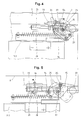
- Fig. 4
- einen Ausschnitt einer Steuerkurve für die Betätigung des Mitnehmerparallelogrammes, als Bindeglied zwischen dem Türantrieb und der Teleskop-Kabinentür, in einer geschlossenen Stellung;
- Fig. 5
- einen Ausschnitt der Steuerkurve für die Betätigung des Mitnehmerparallelogrammes in einer offenen Stellung;
- Fig. 6
- eine Ansicht des Mitnehmerparallelogrammes in einer geschlossenen Stellung mit einem verriegelten Kabinentürriegel, strichpunktiert angedeutet, die beiden anderen möglichen Stellungen des Mitnehmerparallelogrammes, in einer offenen und in einer durch die Kupplungsrollen einer Schachttür begrenzten halboffenen Stellung;
- Fig. 7
- einen Seitenriss des Mitnehmerparallelogrammes gemäss Fig. 6;
- Fig. 8
- eine Ansicht der Kabinentürverriegelung in verriegelter Stellung, mit der Steuerkurve und einer Zugstange für die Betätigung des angedeuteten Mitnehmerparallelogrammes und
- Fig. 9
- eine Ansicht der Kabinentürverriegelung in entriegelter Stellung, mit der Steuerkurve, der Zugstange für die Betätigung des angedeuteten Mitnehmerparallelogrammes und einer Einrichtung für die Entriegelung der Kabinentürverriegelung.
- Fig. 1
- a view of a door drive device with a three-leaf telescopic cabin sliding door Door suspensions and the driver parallelogram;
- Fig. 2
- a floor plan of the three-wing telescopic cabin sliding door with the door suspensions and indicated the driving parallelogram and the clutch rollers of a shaft door;
- Fig. 3
- a side elevation of the door drive device with the door suspensions and the door wings to the telescopic cabin sliding door;
- Fig. 4
- a section of a control curve for the actuation of the driver parallelogram, as a link between the door drive and the telescopic cabin door, in a closed position;
- Fig. 5
- a section of the control curve for the actuation of the driver parallelogram in an open position;
- Fig. 6
- a view of the driver parallelogram in a closed position with a locked car door latch, indicated by dash-dotted lines, the two other possible positions of the driver parallelogram, in an open and in a semi-open position limited by the coupling rollers of a shaft door;
- Fig. 7
- a side elevation of the driver parallelogram according to FIG. 6;
- Fig. 8
- a view of the cabin door lock in the locked position, with the control curve and a pull rod for the actuation of the indicated parallelogram and
- Fig. 9
- a view of the car door lock in the unlocked position, with the control curve, the pull rod for actuating the indicated parallelogram and a device for unlocking the car door lock.
In den Figuren 1, 2 und 3 ist mit 1 ein Türantrieb einer Aufzugsanlage bezeichnet. Der Türantrieb 1 besteht aus einem Antriebsmotor 2, einem Vorgelege 3, einem Antriebsriemen 4, einer Antriebsrolle 5, einer spannbaren Umlenkrolle 6 und einem bandförmigen Antriebsmittel 7. Der Türantrieb 1 ist über einer Türöffnung 8 auf einem am Dach einer Aufzugskabine angeordneten Blechträger 9 aufgebaut. Am gleichen Blechträger 9 sind auch Führungsschienen 10.1, 10.2, 10.3 angeordnet, für die Aufnahme von Schiebewagen 11.1, 11.2, 11.3, welche je einen einzelnen Türflügel 12.1, 12.2, 12.3 tragen. Der erste Schiebewagen 11.1 ist mit einem Klemmelement 13, über einen Kniehebel 14 und eine Steuerkurve 15 gelenkig mit dem bandförmigen Antriebsmittel 7 verbunden. Diese Verbindung ist in den Fig. 4 und 5, in einem grösseren Massstab dargestellt, besser ersichtlich. Die beiden anderen Schiebewagen 11.2, 11.3 sind mit an sich bekannten Seilzügen 16, 17 für die Mitnahme miteinander und mit dem ersten Schiebewagen 11.1 verbunden. Die Lage eines am ersten Schiebewagen 11.1 angeordneten Mitnehmerparallelogrammes 18 und eines schwenkbar gelagerten Kabinentürriegels 46, sowie einer festen und einer beweglichen Kupplungsrolle 19, 20 der jeweiligen Schachttür ist strichpunktiert dargestellt.Das Klemmelement 13 ist auf einer am ersten Schiebewagen 11.1 angeordneten Gleitführung 21, innerhalb eines begrenzten Weges gleitend geführt. Die Steuerkurve 15 ist ebenfalls am ersten Schiebewagen 11.1 des ersten Türflügels 12.1 an einer Drehachse 22 eines Haltebleches 23 drehbar gelagert und ragt mit einem Gelenkzapfen 24, in eine Aussparung 25 eines Haltebleches 23 hinein. Sie wird vom Türantrieb 1 über das bandförmige Antriebsmittel 7 durch eine Zugkraft 54 in einer geschlossenen Stellung gehalten (Fig. 4) und durch eine Zugfeder 26 in eine offene Stellung gezogen (Fig. 5). Dabei dient eine am Blechträger 9 angeordnete Rolle 27 als Abwälzrolle für die Kontur der Steuerkurve 15.In Figures 1, 2 and 3, 1 denotes a door drive of an elevator system. The door drive 1 consists of a
In den Fig. 6 bis 9 sind die verschiedenen Stellungen des Mitnehmerparallelogrammes 18 und der Kabinentürverriegelung dargestellt. Das Mitnehmerparallelogramm 18 ist auf einem Tragblech 28 am ersten Schiebewagen 11.1 angeordnet. Es besteht aus zwei Kurven 29, 30, welche gelenkig mit einem oberen 31 und einem unteren Hebel 32 verbunden sind, die ihrerseits auf Gelenkzapfen 33, 34 des Tragbleches 28 drehbar gelagert sind. Am unteren Hebel ist auf einer Achse 35 eine Zugstange 36 angelenkt, welche das Mitnehmerparallelogramm 18 mit der Steuerkurve 15 verbindet. Die Zugstange 36 ist mit einem Längenausgleich 37 ausgerüstet und weist einen Anschlag 38 für einen Doppelhebel 39 und eine Auflaufkurve 40 für eine am Blechträger 23 fest angeordnete Stützrolle 41 auf. Der Doppelhebel 39 ist an einem Ende mit einem Zapfen 42 mit der Zugstange 36 gelenkig verbunden und ruht mit dem mittleren Drehlager auf der in die Aussparung 25 des Haltebleches 23 hineinragenden Achse 24 der Steuerkurve 15. Durch die Kraft einer Zugfeder 43 wird der Doppelhebel 39 in einer Ruhelage an den Anschlag 38 der Zugstange 36 gezogen. An der Achse 24 der Steuerkurve 15 ist ein elastischer Puffer 44 vorgesehen, um die Öffnungsbewegung der Steuerkurve 15 am Ende der Aussparung 25 zu dämpfen. Am oberen Ende des Haltebleches 23 ist ein Drehzapfen 45 vorgesehen, an dem ein Kabinentürriegel 46 schwenkbar gelagert ist. Am vorderen Teil des Kabinentürriegels 46 ist ein Ende einer Betätigungslasche 47 angelenkt, dessen anderes Ende eine in einer Kulisse 48 des Haltebleches 23 geführte Betätigungsrolle 49 aufweist. Am hinteren Teil des Kabinentürriegels 46 ist eine Verriegelungsrolle 50 und eine Kontaktbrücke 51 angeordnet, welche mit einer am Blechträger 9 der Aufzugskabine befestigten Verriegelungskurve 52 und einem, die verriegelte Position der Kabinentürverriegelung überwachenden elektrischen Sicherheitskontakt 53 zusammenarbeiten.6 to 9, the different positions of the
Die vorstehend beschriebene Einrichtung arbeitet wie folgt:
Die in den Fig. 1, 2 und 3 beispielsweise dargestellte dreiflügelige Teleskop-Kabinenschiebetür besteht aus drei Türflügeln 12.1, 12.2, 12.3, welche an drei auf parallel angeordneten Führungsschienen 10.1, 10.2, 10,3 laufenden Schiebewagen 11.1, 11.2, 11.3 angehängt sind. Das Antriebsmittel 7 des Türantriebes 1 ist mit dem Türflügel 12.1 verbunden, welcher den grössten Weg zum Öffnen oder Schliessen der Türöffnung 8 zurücklegen muss. Die beiden anderen Türflügel 12.2, 12.3 sind über, an sich bekannte, Seilzüge 16, 17 indirekt angetrieben, derart, dass gleichzeitig der mittlere Türflügel 12.2, 2/3 und der dritte Türflügel 12.3, 1/3 des Weges des direkt angetriebenen Türflügels 12.1 zurücklegt und beispielsweise bei offener Kabinentür alle drei Türflügel 12.1, 12.2, 12.3 gleichzeitig seitlich ausserhalb der Kabinentüröffnung genau deckend hintereinander liegen. Im geschlossenen Zustand liegen die drei Türflügel 12.1, 12.2, 12.3 gestaffelt hintereinander und decken die Türöffnung 8 gänzlich ab. Der eingeschaltete Kabinentürantrieb 1 wirkt dabei über das bandförmige Antriebsmittel 7 mit der Zugkraft 54 auf den angetriebenen Türflügel 12.1 und bringt die Kabinenschiebetür in die beiden Stellungen.The device described above works as follows:
1, 2 and 3, for example shown three-wing telescopic sliding door consists of three door leaves 12.1, 12.2, 12.3 , which are attached to three sliding carriages 11.1, 11.2, 11.3 running on parallel guide rails 10.1, 10.2, 10.3 . The drive means 7 of the door drive 1 is connected to the door leaf 12.1 , which has to cover the greatest distance for opening or closing the
Die Türantriebsvorrichtung, das Mitnehmerparallelogramm und der Verriegelungsmechanismus haben die Aufgabe, die Kabinentür während der Fahrt der Kabine verriegelt zu halten, in einer Zieletage die Kabinentür und die Schachttür zu entriegeln und zusammenzukuppeln, damit die Schachttür gemeinsam mit der von der Türantriebsvorrichtung betätigten Kabinentür geöffnet und geschlossen wird und beide Türen vor einer Weiterfahrt wieder zu verriegeln. Zusätzlich sind die Vorschriften zu erfüllen, dass bei Stromausfall die Kabinentür ausserhalb des Türöffnungsbereiches einer Etage verriegelt bleiben muss, bzw. im Türöffnungsbereich der Etage die Kabinentür und die entsprechende Schachttür automatisch entriegelt werden, dass beide Türen gemeinsam von einem eingeschlossenen Fahrgast von Hand geöffnet werden können.The function of the door drive device, the driver parallelogram and the locking mechanism are to keep the cabin door locked while the cabin is moving, to unlock and couple the cabin door and the landing door on a target floor so that the landing door opens and closes together with the cabin door operated by the door drive device and both doors again before continuing to lock. In addition, the regulations must be met that, in the event of a power failure, the cabin door must remain locked outside the door opening area of a floor, or in the door opening area of the floor, the cabin door and the corresponding landing door must be unlocked automatically so that both doors can be opened by an enclosed passenger by hand .
In der geschlossenen Endstellung wird die Kabinentür mit dem angetriebenen Türflügel 12.1 verriegelt, siehe dazu die Fig. 1, 4, 6 und 8. Die am bandförmigen Antriebsmittel 7 angreifende Zugkraft 54 wirkt sich über das Klemmelement 13 und den Kniehebel 14, auch auf die Steuerkurve 15 aus, welche, gegen die Kraft der Zugfeder 26, mit ihrer Kontur an die am Blechträger 9 fest angeordnete Rolle 27 gedrückt wird. Dabei nimmt die Zugstange 36 die tiefste Stellung ein und drückt über den unteren Hebel 32 die beiden Kurven 29, 30 des Mitnehmerparallelogrammes 18 in die geschlossene Stellung. Die Kurven 29, 30 des Mitnehmerparallelogrammes 18 entfernen sich von der festen und der beweglichen Kupplungsrolle 19, 20 der Schachttür, wobei sich die bewegliche Kupplungsrolle 20 verschiebt und die Schachttür verriegelt. Ein nicht dargestelter Sicherheitskontakt überwacht die Verriegelung der Schachttür elektrisch. Gleichzeitig wird der schwenkbar gelagerte Kabinentürriegel 46 mit seiner Verriegelungsrolle 50 über die Verriegelungskurve 52 geführt, die Kabinentür verriegelt und der elektrische Sicherheitskontakt 53 durch die Kontaktbrücke 51 geschlossen. In diesem Zustand ist die Aufzugskabine bereit für die Weiterfahrt.In the closed end position, the cabin door is locked with the driven door leaf 12.1 , see FIGS. 1, 4, 6 and 8. The
In einer Zieletage angekommen, wird die Türantriebsvorrichtung 1 umgeschaltet, wobei die Zugkraft 54 am bandförmigen Antriebsmittel 7 ihre Richtung ändert, (siehe dazu Fig. 5, 6 und 9). Bevor die Schiebetür eine Bewegung ausführt, wird das Klemmelement 13 längs der Gleitführung 21 in öffnender Richtung gezogen, wobei die Steuerkurve 15 über den Kniehebel 14 um die Drehachse 22 gedreht wird und sich die Kontur der Steuerkurve 15 an der am Blechträger 9 fest angeordneten Rolle 27 abwälzt. Die Kontur der Steuerkurve 15 ist so ausgeführt, dass ein ruckarmes Öffnen und Schliessen des Mitnehmerparallelogrammes 18 und der Türen auf der Schliesseite gewährleistet ist. Die Steuerkurve dreht sich, bis der elastische Puffer 44 an der in die Aussparung 25 des Haltebleches 23 ragenden Achse 24 am Ende der Aussparung 25 ansteht. In der Zwischenzeit öffnet sich das Mitnehmerparallelogramm 18, betätigt durch die, über den Doppelhebel 39 mit der Steuerkurve 15 verbundene Zugstange 36, bis die beiden Kurven 29, 30 des Mitnehmerparallelogrammes 18 an der festen und an der beweglichen Kupplungsrolle 19, 20 der anwesenden Schachttür anstehen. Dabei wird die bewegliche Kupplungsrolle 20 um eine gewisse Distanz weggedrückt und dadurch die Schachttür entriegelt. Das Mitnehmerparallelogramm 18 nimmt die in Fig. 6 strichpunktiert angedeutete Mittelstellung ein, bei welcher die leicht schräggestellte Zugstange 36 mit der Auflaufkurve 40 an der Stützrolle 41 aufsteht und der Doppelhebel 39 gegen die Kraft der Feder 43 hochgedrückt wird und der Doppelhebel 25 seinerseits die Betätigungsrolle 49 des Kabinentürriegels 46 hochdrückt. Dabei wird der Kabinentürriegel 46 über die Betätigungslasche 47 um den Drehzapfen 45 geschwenkt und die Verriegelungsrolle 50 aus der Verriegelung geführt. Die Kabinentür kann nun vom Türantrieb 1 gänzlich geöffnet werden.Arrived on a target floor, the door drive device 1 is switched over, the
Befindet sich eine Aufzugskabine bei Stromausfall innerhalb des Türöffnungsbereiches einer Etage, erfolgt die Entriegelung der Schachttürverriegelung und der Kabinentürverriegelung in der gleichen, oben dargestellten Weise, mit der Ausnahme, dass an die Stelle der Zugkraft 54, welche vom Türantrieb 1 auf die Steuerkurve 15 wirkt, die Kraft der Zugfeder 26 tritt, welche die Steuerkurve 15 dreht, das Klemmelement 13 mit dem bandförmigen Antriebsmittel 7 in der Gleitführung 21 verschiebt, das Mitnehmerparallelogramm 18 öffnet und die Schachttürverriegelung und die Kabinentürverriegelung entriegelt. Ein eventuell eingeschlossener Fahrgast hat dann die Möglichkeit, die Kabinentür und die angekuppelte Schachttür gemeinsam von Hand zu öffnen.If an elevator car is located within the door opening area of one floor in the event of a power failure, the shaft door lock and the car door lock are unlocked in the same manner as shown above, with the exception that the
Befindet sich eine Aufzugskabine bei Stromausfall ausserhalb der Türöffnungszone einer Etage, erfolgt keine Entriegelung der Kabinentürverriegelung. Bei Stromausfall entfällt wiederum die Zugkraft 54 auf die Steuerkurve 15. Die Kraft der Zugfeder 26 zieht an der Steuerkurve 15 und dreht sie um ihre Drehachse 22, wobei die Kontur der Steuerkurve 15 sich an der am Blechträger 9 fest angeordneten Rolle 27 abwälzt bis der elastische Puffer 44 an der in die Aussparung 25 des Haltebleches 23 ragenden Achse 24 am Ende der Aussparung 25 ansteht. Dabei wird das Klemmelement 13 mit dem bandförmigen Antriebsmittel 7 über den Kniehebel 14 auf der Gleitführung 21 in öffnender Richtung verschoben und das Mitnehmerparallelogramm 18 über die Zugstange 36 geöffnet. Da keine Kupplungsrollen 19, 20 einer Schachttür anwesend sind, öffnet sich das Mitnehmerparallelogramm 18 maximal, wobei die Zugstange 36 die höchste Stellung einnimmt, bei welcher der Doppelhebel 39 um die Achse 24 auf der Zugstangenseite hochgedrückt und auf der Entriegelungsseite nach unten gedrückt wird. Die Betätigungsrolle 49 des Kabinentürriegels 46 wird nicht verschoben und die Kabinentürverriegelung bleibt verriegelt. Ein eventuell eingeschlossener Fahrgast kann die Kabinentür nicht von Hand öffnen, (siehe dazu Fig. 8).If there is an elevator car outside the door opening zone on one floor in the event of a power failure, the car door lock is not unlocked. In the event of a power failure, the
In vorstehender Beschreibung und in den Fig. 1, 2 und 3 ist eine Teleskopschiebetür mit drei Türflügeln dargestellt. Es ist ohne weiteres möglich, mit der erfindungsgemässen Türantriebsvorrichtung jede andere Schiebetürart auszurüsten, beispielsweise auch eine zentral öffnende Teleskopschiebetür.In the above description and in FIGS. 1, 2 and 3, a telescopic sliding door with three door leaves is shown. It is readily possible to equip any other type of sliding door with the door drive device according to the invention, for example also a centrally opening telescopic sliding door.
Anstelle eines bandförmigen Antriebsmittel für die Übertragung der Öffnungs- und Schliessbewegungen, vom Türantrieb auf die Türflügel, könnte auch ein anderes Antriebsmittel, beispielsweise ein Schubkurbelantrieb vorgesehen werden.Instead of a belt-shaped drive means for transmitting the opening and closing movements, from the door drive to the door leaf, another drive means, for example a push crank drive, could also be provided.
Es kommt vor, dass beim gleichen Aufzug ungleich hohe Schachttüren mit einer Türantriebsvorrichtung für die Kabinentür gekuppelt und betätigt werden müssen, beispielsweise höhere Schachttüren im Erdgeschoss und niedrigere Schachttüren in den übrigen Etagen. Kabine und Kabinentür werden dabei für die höchste Schachttür ausgelegt. Mit der erfindungsgemässen Türantriebsvorrichtung ist es ohne weiteres möglich, die Höhenlage des Mitnehmerparallelogrammes für das Ankuppeln der Schachttüren, an die niedrigste Schachttür anzupassen und für die Bedienung der am oberen Ende eines Kabinentürflügels angeordneten Kabinentürverriegelung bzw. der Entriegelungsbetätigung dieser Kabinentürverriegelung, einzig die Zugstange 36 zu verlängern.It happens that, for the same elevator, shaft doors of different heights have to be coupled and actuated with a door drive device for the car door, for example higher shaft doors on the ground floor and lower shaft doors on the other floors. The cabin and cabin door are designed for the highest shaft door. With the door drive device according to the invention, it is readily possible to adapt the height of the driver parallelogram for coupling the shaft doors to the lowest shaft door and for the operation of the car door lock arranged at the upper end of a car door wing or the unlocking actuation of this car door lock, only to extend the
Claims (6)
dadurch gekennzeichnet, dass das an der Kabinentür angeordnete Betätigungsorgan eine das Mitnehmerparallelogramm (18) über eine Zugstange (36) betätigende Steuerkurve (15) ist, welche an einem Schiebewagen (11.1) eines Schiebetürflügels (12.1) drehbar gelagert und über einen Kniehebel (14) gelenkig mit dem Antriebsmittel (7) verbunden ist, und dass auf der Schliesseite am Blechträger (9) eine unverschieblich und drehbar gelagerte Rolle (27) angeordnet ist, auf welcher sich die Kontur der Steuerkurve (15) abwälzt.Door drive device with locking mechanism for lifts, in which a car door that can be connected to a shaft door by a coupling mechanism can be moved by a door drive ( 1 ) in the area of the floors, the coupling mechanism consisting of a driver parallelogram ( 18 ) mounted on a car door leaf ( 11.1 ) and two each Each shaft door arranged clutch rollers ( 19, 20 ) and the door drive ( 1 ) has a drive motor ( 2 ) arranged above the cabin, a countershaft ( 3 ) and a belt-shaped drive means ( 7 ) which is connected to the cabin door by an actuator and the car door in the closed and in the open position is fixed and the locking mechanism a monitored by a safety contact (53) pivotally mounted lockable against a stop cage door latch (46) which is locked by its own weight in a retaining position and a Press shutter can be pressed into a release position,
characterized in that the actuating element arranged on the cabin door is a control cam ( 15 ) actuating the driver parallelogram ( 18 ) via a pull rod ( 36 ), which is rotatably mounted on a sliding carriage ( 11.1 ) of a sliding door leaf ( 12.1 ) and via a toggle lever ( 14 ) is articulated to the drive means ( 7 ), and that on the closing side on the sheet metal support ( 9 ) there is a non-displaceable and rotatably mounted roller ( 27 ) on which the contour of the control cam ( 15 ) rolls.
dadurch gekennzeichnet, dass an der Steuerkurve (15) eine in eine Aussparung (25) eines Haltebleches (23) ragende Achse (24) angeordnet ist, welche einen die Drehung der Steuerkurve (15) in öffnender Richtung begrenzenden am Ende der Aussparung (25) anstehenden elastischen Puffer (44) aufweist.Door drive device according to claim 1
characterized in that on the control cam ( 15 ) projects into a recess ( 25 ) of a holding plate ( 23 ) Axis ( 24 ) is arranged, which has an elastic buffer ( 44 ), which limits the rotation of the control cam ( 15 ) in the opening direction and is present at the end of the recess ( 25 ).
dadurch gekennzeichnet, dass die Betätigungseinrichtung für den Kabinentürriegel (46) ein in einer Kulisse (48) des Haltebleches (23) geführte eine Betätigungsrolle (49) aufweisende gelenkig mit dem Kabinentürriegel (46) verbundene Betätigungslasche (47) ist, welche durch einen auf der Achse (24) der Steuerkurve (15) gelagerten und mit der Zugstange (36) gelenkig verbundenen auf die Betätigungsrolle (49) wirkenden Doppelhebel (39) hochdrückbar ist.Door drive device according to claim 1
characterized in that the actuating device for the car door latch ( 46 ) is an actuating lug ( 47 ) which is guided in a link ( 48 ) of the holding plate ( 23 ) and has an actuating roller ( 49 ) which is articulated to the car door latch ( 46 ) and which is actuated by a Axle ( 24 ) of the control cam ( 15 ) mounted and articulated with the pull rod ( 36 ) on the actuating roller ( 49 ) acting double lever ( 39 ) can be pushed up.
dadurch gekennzeichnet, dass die Zugstange (36) eine in einer Offenstellung des Mitnehmerparallelogrammes (18) auf eine am Tragblech (23) fest angeordnete Stützrolle (41) auflaufende Auflaufkurve (40) aufweist.Door drive device according to claim 1
characterized in that the pull rod ( 36 ) has a run-up curve ( 40 ) running in an open position of the driver parallelogram ( 18 ) onto a support roller ( 41 ) fixedly arranged on the support plate ( 23 ).
dadurch gekennzeichnet, dass die Zugstange (36) einen eine genaue Länge einstellbaren Längenausgleich (37) aufweist.Door drive device according to claim 1
characterized in that the pull rod ( 36 ) has a length compensation ( 37 ) which can be adjusted to an exact length.
dadurch gekennzeichnet, dass die Zugstange (36) einen den Doppelhebel (39) durch die Kraft einer Zugfeder (43) in einer Ruhelage haltenden Anschlag (38) aufweist.Door drive device according to claim 3
characterized in that the pull rod ( 36 ) has a stop ( 38 ) holding the double lever ( 39 ) in a rest position by the force of a tension spring ( 43 ).
Applications Claiming Priority (2)
| Application Number | Priority Date | Filing Date | Title |
|---|---|---|---|
| CH1436/91 | 1991-05-14 | ||
| CH143691 | 1991-05-14 |
Publications (2)
| Publication Number | Publication Date |
|---|---|
| EP0513509A1 true EP0513509A1 (en) | 1992-11-19 |
| EP0513509B1 EP0513509B1 (en) | 1995-11-22 |
Family
ID=4210425
Family Applications (1)
| Application Number | Title | Priority Date | Filing Date |
|---|---|---|---|
| EP92105573A Expired - Lifetime EP0513509B1 (en) | 1991-05-14 | 1992-04-01 | Elevator |
Country Status (20)
| Country | Link |
|---|---|
| US (1) | US5246089A (en) |
| EP (1) | EP0513509B1 (en) |
| JP (1) | JP3192474B2 (en) |
| KR (1) | KR960001526B1 (en) |
| CN (1) | CN1028743C (en) |
| AT (1) | ATE130581T1 (en) |
| AU (1) | AU647921B2 (en) |
| CA (1) | CA2065588C (en) |
| DE (1) | DE59204394D1 (en) |
| DK (1) | DK0513509T3 (en) |
| ES (1) | ES2083012T3 (en) |
| FI (1) | FI101529B (en) |
| GR (1) | GR3018752T3 (en) |
| HK (1) | HK25097A (en) |
| HU (1) | HU209748B (en) |
| MX (1) | MX9202212A (en) |
| NO (1) | NO302878B1 (en) |
| RU (1) | RU2035374C1 (en) |
| TR (1) | TR25720A (en) |
| ZA (1) | ZA923464B (en) |
Cited By (12)
| Publication number | Priority date | Publication date | Assignee | Title |
|---|---|---|---|---|
| FR2717166A1 (en) * | 1994-03-10 | 1995-09-15 | Mitsubishi Electric Corp | Lift door structure and its adjustment |
| EP0701961A1 (en) * | 1994-09-16 | 1996-03-20 | Thyssen Ascenseurs | Driving device for door leaf of elevator car |
| DE29508499U1 (en) * | 1995-05-22 | 1996-09-26 | Meiller Fahrzeuge | Actuator for an elevator door combination |
| WO1997037923A1 (en) * | 1996-04-10 | 1997-10-16 | Otis Elevator Company | Elevator evacuation deterrent device |
| US5918706A (en) * | 1997-11-24 | 1999-07-06 | Otis Elevator Company | Hold closed feature for elevator car doors |
| US6021871A (en) * | 1996-10-29 | 2000-02-08 | Inventio Ag | Apparatus for opening and closing a car door and a shaft door of an elevator installation |
| US6513628B2 (en) | 1996-08-13 | 2003-02-04 | Inventio Ag | Support for lift door drive |
| EP1541517A1 (en) * | 2003-12-08 | 2005-06-15 | Inventio Ag | Device on an elevator car for temporaly coupling a car door panel with a landing door panel and for actuating a car door locking mechanism |
| CN100383030C (en) * | 2003-12-08 | 2008-04-23 | 因温特奥股份公司 | Door drive device for an elevator |
| EP1930285A1 (en) * | 2006-09-28 | 2008-06-11 | Inventio Ag | Lift facility with a safety device fitted on the lift doors |
| DE112010003974B4 (en) * | 2009-10-09 | 2014-05-15 | Mitsubishi Electric Corporation | Door engagement device for a lift |
| CN104003269A (en) * | 2014-03-27 | 2014-08-27 | 昆山御广峰机械有限公司 | Elevator retiring cam drive device |
Families Citing this family (40)
| Publication number | Priority date | Publication date | Assignee | Title |
|---|---|---|---|---|
| US5538106A (en) * | 1994-04-08 | 1996-07-23 | Otis Elevator Company | Rotationally stiff elevator car door coupling |
| EP0679602A1 (en) * | 1994-04-25 | 1995-11-02 | Inventio Ag | Engaging device for elevator doors |
| ES2119650B1 (en) * | 1995-08-04 | 1999-05-16 | Technoresearch Promotion Sa | AUTOMATIC OPENING AND CLOSING DEVICE FOR CABIN DOOR AND LIFT FILLING LEAVES. |
| FI101784B1 (en) * | 1995-09-13 | 1998-08-31 | Kone Corp | A method for moving an elevator level door and a taker |
| FI100517B (en) * | 1995-09-13 | 1997-12-31 | Kone Oy | Method of closing the elevator level door and the participant |
| US6173815B1 (en) * | 1997-02-28 | 2001-01-16 | Kone Corporation | Door coupler and locking device |
| KR100303010B1 (en) * | 1998-12-07 | 2002-05-09 | 장병우 | Elevator clutch device |
| KR100286356B1 (en) * | 1998-12-15 | 2001-05-02 | 장병우 | Engagement device of elevator door |
| IT1313630B1 (en) * | 1999-09-27 | 2002-09-09 | Prisma S R L | OPENING / CLOSING DEVICE FOR LIFT DOORS. |
| KR100347171B1 (en) * | 2000-06-01 | 2002-08-03 | 현대엘리베이터주식회사 | Structure of elevator door opening and shutting apparatus |
| MY137162A (en) * | 2001-06-14 | 2009-01-30 | Inventio Ag | Equipment for connecting a cage door with a shaft door |
| AT412339B (en) * | 2002-04-22 | 2005-01-25 | Wittur Gmbh | DEVICE FOR OPERATING AND LOCKING OF LIFTING DOORS WITH PICKING FEET |
| JP4245371B2 (en) * | 2003-02-21 | 2009-03-25 | 東芝エレベータ株式会社 | Elevator door equipment |
| ZA200406978B (en) * | 2003-09-17 | 2005-06-20 | Inventio Ag | Device for connecting a cage door with a shaft door and for locking and unlocking the doors, a device for emergency unlocking of a cage door and a method for emergency unlocking of a cage door. |
| JP4544887B2 (en) * | 2004-03-26 | 2010-09-15 | 東芝エレベータ株式会社 | Elevator door device |
| AT414115B (en) * | 2004-09-17 | 2006-09-15 | Knorr Bremse Gmbh | BOTTOM LOCK |
| ITMI20042249A1 (en) * | 2004-11-19 | 2005-02-19 | Sematic Italia Spa | ACTIVE SLIDE FOR LIFT CABIN DOORS |
| EP1841682B1 (en) * | 2005-01-28 | 2014-03-19 | Mitsubishi Denki Kabushiki Kaisha | Elevator car door locking apparatus |
| JP2006290566A (en) * | 2005-04-12 | 2006-10-26 | Toshiba Elevator Co Ltd | Door device for elevator |
| EA008456B1 (en) * | 2006-03-31 | 2007-06-29 | Республиканское Унитарное Предприятие Завод "Могилевлифтмаш" | Device for moving an elevator door |
| US7398862B2 (en) * | 2006-06-02 | 2008-07-15 | The Peelle Company Ltd. | Car door lock |
| CN101161581B (en) * | 2006-10-13 | 2011-06-15 | 意大利思迈特迪克公司 | Movable sliding pieces for elevator car door |
| EP2138442A1 (en) * | 2008-06-25 | 2009-12-30 | Inventio Ag | Elevator door system with cabin door locking |
| JP5403327B2 (en) * | 2009-01-27 | 2014-01-29 | 富士電機株式会社 | Sliding door opening and closing device for vehicles |
| EP2287104B1 (en) * | 2009-08-21 | 2013-08-28 | Wittur Deutschland Holding GmbH | Door coupler and locking mechanism |
| JP2011088720A (en) * | 2009-10-23 | 2011-05-06 | Toshiba Elevator Co Ltd | Elevator door device |
| EP2459476B1 (en) * | 2009-12-16 | 2013-06-05 | ThyssenKrupp Elevator AG | Device for entraining a shaft door by means of an elevator car door |
| WO2013036176A2 (en) * | 2011-09-09 | 2013-03-14 | Lukyanov Pavel Evgenievich | Opening/closing mechanism for sliding doors |
| CN102502382B (en) * | 2011-12-26 | 2013-08-14 | 日立电梯(中国)有限公司 | Heavy punch type lift car door lock mechanism |
| BR112014030335B1 (en) * | 2012-06-18 | 2021-04-06 | Sematic S.P.A. | ELEVATOR CAB DOOR WITH A LOCKING / RELEASE DEVICE FOR THE MECHANISMS |
| TR201903994T4 (en) * | 2014-03-19 | 2019-04-22 | Wittur Holding Gmbh | Blocking system and group for elevator doors. |
| JP6250190B2 (en) * | 2014-10-15 | 2017-12-20 | 三菱電機株式会社 | Elevator car door device |
| CN104787651B (en) * | 2015-02-13 | 2016-06-22 | 西子奥的斯电梯有限公司 | A kind of elevator synchronous door knife |
| EP3187452B1 (en) * | 2016-01-04 | 2021-01-27 | Otis Elevator Company | Elevator door coupler assembly |
| EP3759041A4 (en) * | 2018-02-28 | 2021-09-08 | KONE Corporation | Elevator landing door assembly and its installation method |
| US11390492B2 (en) | 2018-05-01 | 2022-07-19 | Otis Elevator Company | Method and assembly for positioning an elevator door interlock |
| CN113544076B (en) * | 2019-03-18 | 2023-01-03 | 三菱电机株式会社 | Elevator car door device |
| KR102294066B1 (en) * | 2020-01-28 | 2021-08-26 | (주)에이엔티 | Device for elevator door simulation |
| JP7204051B2 (en) * | 2020-06-09 | 2023-01-13 | 三菱電機株式会社 | elevator car door device |
| CN113942913B (en) * | 2021-09-27 | 2023-05-30 | 日立电梯(中国)有限公司 | Elevator car door machine, elevator car and elevator door opening and closing control method |
Citations (4)
| Publication number | Priority date | Publication date | Assignee | Title |
|---|---|---|---|---|
| US3605952A (en) * | 1969-09-30 | 1971-09-20 | Otis Elevator Co | Door coupling apparatus for elevator systems |
| FR2461674A1 (en) * | 1979-07-21 | 1981-02-06 | Haushahn C Gmbh Co | DOOR CONTROL DEVICE, ESPECIALLY ELEVATOR DOOR |
| FR2625991A1 (en) * | 1988-01-14 | 1989-07-21 | Soretex | Device for driving a lift car door |
| EP0332841A1 (en) * | 1988-03-18 | 1989-09-20 | Inventio Ag | Door actuating apparatus with a locking mechanism for lifts |
Family Cites Families (2)
| Publication number | Priority date | Publication date | Assignee | Title |
|---|---|---|---|---|
| US2816625A (en) * | 1956-09-21 | 1957-12-17 | Westinghouse Electric Corp | Elevator system having door operators |
| CH663406A5 (en) * | 1984-05-28 | 1987-12-15 | Inventio Ag | DOOR DRIVE DEVICE WITH LOCKING MECHANISM FOR ELEVATORS. |
-
1992
- 1992-04-01 ES ES92105573T patent/ES2083012T3/en not_active Expired - Lifetime
- 1992-04-01 DE DE59204394T patent/DE59204394D1/en not_active Expired - Lifetime
- 1992-04-01 EP EP92105573A patent/EP0513509B1/en not_active Expired - Lifetime
- 1992-04-01 DK DK92105573.7T patent/DK0513509T3/en not_active Application Discontinuation
- 1992-04-01 AT AT92105573T patent/ATE130581T1/en not_active IP Right Cessation
- 1992-04-08 CA CA002065588A patent/CA2065588C/en not_active Expired - Fee Related
- 1992-05-08 RU SU5011595/11A patent/RU2035374C1/en not_active IP Right Cessation
- 1992-05-12 JP JP11902492A patent/JP3192474B2/en not_active Expired - Fee Related
- 1992-05-12 TR TR92/0468A patent/TR25720A/en unknown
- 1992-05-12 HU HU9201574A patent/HU209748B/en not_active IP Right Cessation
- 1992-05-13 MX MX9202212A patent/MX9202212A/en active IP Right Grant
- 1992-05-13 AU AU16214/92A patent/AU647921B2/en not_active Ceased
- 1992-05-13 ZA ZA923464A patent/ZA923464B/en unknown
- 1992-05-13 CN CN92103531A patent/CN1028743C/en not_active Expired - Lifetime
- 1992-05-13 FI FI922162A patent/FI101529B/en not_active IP Right Cessation
- 1992-05-13 NO NO921882A patent/NO302878B1/en unknown
- 1992-05-14 US US07/882,700 patent/US5246089A/en not_active Expired - Lifetime
- 1992-05-14 KR KR1019920008107A patent/KR960001526B1/en not_active IP Right Cessation
-
1996
- 1996-01-19 GR GR960400141T patent/GR3018752T3/en unknown
-
1997
- 1997-02-27 HK HK25097A patent/HK25097A/en not_active IP Right Cessation
Patent Citations (4)
| Publication number | Priority date | Publication date | Assignee | Title |
|---|---|---|---|---|
| US3605952A (en) * | 1969-09-30 | 1971-09-20 | Otis Elevator Co | Door coupling apparatus for elevator systems |
| FR2461674A1 (en) * | 1979-07-21 | 1981-02-06 | Haushahn C Gmbh Co | DOOR CONTROL DEVICE, ESPECIALLY ELEVATOR DOOR |
| FR2625991A1 (en) * | 1988-01-14 | 1989-07-21 | Soretex | Device for driving a lift car door |
| EP0332841A1 (en) * | 1988-03-18 | 1989-09-20 | Inventio Ag | Door actuating apparatus with a locking mechanism for lifts |
Cited By (20)
| Publication number | Priority date | Publication date | Assignee | Title |
|---|---|---|---|---|
| FR2717166A1 (en) * | 1994-03-10 | 1995-09-15 | Mitsubishi Electric Corp | Lift door structure and its adjustment |
| EP0701961A1 (en) * | 1994-09-16 | 1996-03-20 | Thyssen Ascenseurs | Driving device for door leaf of elevator car |
| FR2724643A1 (en) * | 1994-09-16 | 1996-03-22 | Thyssen Ascenseurs | DRIVE DEVICE FOR ELEVATOR CAB DOOR LEAF |
| DE29508499U1 (en) * | 1995-05-22 | 1996-09-26 | Meiller Fahrzeuge | Actuator for an elevator door combination |
| EP0744373A2 (en) * | 1995-05-22 | 1996-11-27 | Franz Xaver Meiller Fahrzeug- und Maschinenfabrik-GmbH & Co KG | Operating device for elevator door |
| EP0744373A3 (en) * | 1995-05-22 | 1997-01-22 | Franz Xaver Meiller Fahrzeug- und Maschinenfabrik-GmbH & Co KG | Operating device for elevator door |
| WO1997037923A1 (en) * | 1996-04-10 | 1997-10-16 | Otis Elevator Company | Elevator evacuation deterrent device |
| US5819877A (en) * | 1996-04-10 | 1998-10-13 | Otis Elevator Company | Elevator evacuation deterrent device |
| US6513628B2 (en) | 1996-08-13 | 2003-02-04 | Inventio Ag | Support for lift door drive |
| US6021871A (en) * | 1996-10-29 | 2000-02-08 | Inventio Ag | Apparatus for opening and closing a car door and a shaft door of an elevator installation |
| US5918706A (en) * | 1997-11-24 | 1999-07-06 | Otis Elevator Company | Hold closed feature for elevator car doors |
| EP1541517A1 (en) * | 2003-12-08 | 2005-06-15 | Inventio Ag | Device on an elevator car for temporaly coupling a car door panel with a landing door panel and for actuating a car door locking mechanism |
| US7100745B2 (en) | 2003-12-08 | 2006-09-05 | Inventio Ag | Equipment at an elevator car for temporarily coupling a car door leaf with a shaft door leaf for actuation of a car door unlocking means |
| CN100379672C (en) * | 2003-12-08 | 2008-04-09 | 因温特奥股份公司 | Equipment at a lift cage for temporarily coupling a cage door leaf with a shaft door leaf and for actuation of a cage door unlocking means |
| CN100383030C (en) * | 2003-12-08 | 2008-04-23 | 因温特奥股份公司 | Door drive device for an elevator |
| EP1930285A1 (en) * | 2006-09-28 | 2008-06-11 | Inventio Ag | Lift facility with a safety device fitted on the lift doors |
| US7637356B2 (en) | 2006-09-28 | 2009-12-29 | Inventio Ag | Elevator system with safety device on elevator doors |
| DE112010003974B4 (en) * | 2009-10-09 | 2014-05-15 | Mitsubishi Electric Corporation | Door engagement device for a lift |
| US8973714B2 (en) | 2009-10-09 | 2015-03-10 | Mitsubishi Electric Corporation | Door engagement device for elevator |
| CN104003269A (en) * | 2014-03-27 | 2014-08-27 | 昆山御广峰机械有限公司 | Elevator retiring cam drive device |
Also Published As
| Publication number | Publication date |
|---|---|
| ATE130581T1 (en) | 1995-12-15 |
| FI922162A (en) | 1992-11-15 |
| US5246089A (en) | 1993-09-21 |
| TR25720A (en) | 1993-09-01 |
| KR920021430A (en) | 1992-12-18 |
| MX9202212A (en) | 1992-11-01 |
| KR960001526B1 (en) | 1996-02-01 |
| AU647921B2 (en) | 1994-03-31 |
| NO921882D0 (en) | 1992-05-13 |
| CN1028743C (en) | 1995-06-07 |
| DK0513509T3 (en) | 1996-03-18 |
| ES2083012T3 (en) | 1996-04-01 |
| GR3018752T3 (en) | 1996-04-30 |
| JPH05178569A (en) | 1993-07-20 |
| RU2035374C1 (en) | 1995-05-20 |
| HK25097A (en) | 1997-02-27 |
| HU9201574D0 (en) | 1992-08-28 |
| CN1068544A (en) | 1993-02-03 |
| ZA923464B (en) | 1993-01-27 |
| FI101529B1 (en) | 1998-07-15 |
| NO921882L (en) | 1992-11-16 |
| NO302878B1 (en) | 1998-05-04 |
| AU1621492A (en) | 1992-11-19 |
| HUT61243A (en) | 1992-12-28 |
| JP3192474B2 (en) | 2001-07-30 |
| CA2065588A1 (en) | 1992-11-15 |
| CA2065588C (en) | 2003-10-28 |
| FI101529B (en) | 1998-07-15 |
| EP0513509B1 (en) | 1995-11-22 |
| FI922162A0 (en) | 1992-05-13 |
| HU209748B (en) | 1994-10-28 |
| DE59204394D1 (en) | 1996-01-04 |
Similar Documents
| Publication | Publication Date | Title |
|---|---|---|
| EP0513509B1 (en) | Elevator | |
| EP0332841B1 (en) | Door actuating apparatus with a locking mechanism for lifts | |
| EP0164581B1 (en) | Door drive device with a lock mechanism for a lift | |
| EP0383086B1 (en) | Lift car with a modified door coupling | |
| EP1516847B1 (en) | Device to couple car and landing doors and device for emergency unlocking of the car door | |
| EP0196488B1 (en) | Swinging and sliding door, especially for railway carriages | |
| EP2287104B1 (en) | Door coupler and locking mechanism | |
| EP1541517A1 (en) | Device on an elevator car for temporaly coupling a car door panel with a landing door panel and for actuating a car door locking mechanism | |
| EP1541518B1 (en) | Door drive device for an elevator | |
| DE602004012327T2 (en) | CONSUMERS FOR LIFT CABINS AND BAY DOORS | |
| DE69633978T2 (en) | DEVICE FOR OPENING AND CLOSING AUTOMATIC DOORS OF AN ELEVATOR | |
| DE1104985B (en) | Roller plate device for closing openings in open-topped rooms in fixed or mobile systems in vehicles | |
| EP1266860A1 (en) | Device for connecting a car door and a shaft door | |
| DE69632957T2 (en) | METHOD FOR OPERATING AN ELEVATOR SHAFT DOOR AND DOOR COUPLING DEVICE | |
| EP1794399B1 (en) | Floor lock | |
| EP3663158A1 (en) | Step system for a vehicle | |
| EP0839753B1 (en) | Device for opening and closing a car door and a hatchway door of an elevator | |
| EP0679602A1 (en) | Engaging device for elevator doors | |
| DE4441929A1 (en) | Access platform for low floor omnibus | |
| EP0829446A1 (en) | Engaging device for elevator doors | |
| EP0094607A2 (en) | Inclined lift for a wheel chair or the like mounted on a vehicle | |
| DE4221493C2 (en) | Combined unlocking and locking mechanism for an emergency exit door located on the front of a local rail vehicle | |
| EP3924285B1 (en) | Elevator system | |
| DE10261157A1 (en) | Automatic folding door system for escape and rescue routes has emergency release fitting enabling panels to be partly opened in emergency by separating linear guide device and inner door panel | |
| DE60032698T2 (en) | Device for opening and closing elevator door wings |
Legal Events
| Date | Code | Title | Description |
|---|---|---|---|
| PUAI | Public reference made under article 153(3) epc to a published international application that has entered the european phase |
Free format text: ORIGINAL CODE: 0009012 |
|
| AK | Designated contracting states |
Kind code of ref document: A1 Designated state(s): AT BE CH DE DK ES FR GB GR IT LI LU NL PT SE |
|
| 17P | Request for examination filed |
Effective date: 19930420 |
|
| 17Q | First examination report despatched |
Effective date: 19940719 |
|
| GRAA | (expected) grant |
Free format text: ORIGINAL CODE: 0009210 |
|
| AK | Designated contracting states |
Kind code of ref document: B1 Designated state(s): AT BE CH DE DK ES FR GB GR IT LI LU NL PT SE |
|
| REF | Corresponds to: |
Ref document number: 130581 Country of ref document: AT Date of ref document: 19951215 Kind code of ref document: T |
|
| REF | Corresponds to: |
Ref document number: 59204394 Country of ref document: DE Date of ref document: 19960104 |
|
| GBT | Gb: translation of ep patent filed (gb section 77(6)(a)/1977) |
Effective date: 19951216 |
|
| ITF | It: translation for a ep patent filed |
Owner name: MODIANO & ASSOCIATI S.R.L. |
|
| ET | Fr: translation filed | ||
| REG | Reference to a national code |
Ref country code: DK Ref legal event code: T3 |
|
| REG | Reference to a national code |
Ref country code: GR Ref legal event code: FG4A Free format text: 3018752 |
|
| REG | Reference to a national code |
Ref country code: ES Ref legal event code: FG2A Ref document number: 2083012 Country of ref document: ES Kind code of ref document: T3 |
|
| SC4A | Pt: translation is available |
Free format text: 960117 AVAILABILITY OF NATIONAL TRANSLATION |
|
| PLBE | No opposition filed within time limit |
Free format text: ORIGINAL CODE: 0009261 |
|
| STAA | Information on the status of an ep patent application or granted ep patent |
Free format text: STATUS: NO OPPOSITION FILED WITHIN TIME LIMIT |
|
| 26N | No opposition filed | ||
| REG | Reference to a national code |
Ref country code: GB Ref legal event code: IF02 |
|
| PGFP | Annual fee paid to national office [announced via postgrant information from national office to epo] |
Ref country code: PT Payment date: 20070330 Year of fee payment: 16 |
|
| PGFP | Annual fee paid to national office [announced via postgrant information from national office to epo] |
Ref country code: DK Payment date: 20070412 Year of fee payment: 16 Ref country code: LU Payment date: 20070412 Year of fee payment: 16 Ref country code: SE Payment date: 20070412 Year of fee payment: 16 |
|
| PGFP | Annual fee paid to national office [announced via postgrant information from national office to epo] |
Ref country code: NL Payment date: 20070413 Year of fee payment: 16 Ref country code: AT Payment date: 20070413 Year of fee payment: 16 |
|
| PGFP | Annual fee paid to national office [announced via postgrant information from national office to epo] |
Ref country code: BE Payment date: 20070502 Year of fee payment: 16 |
|
| PGFP | Annual fee paid to national office [announced via postgrant information from national office to epo] |
Ref country code: CH Payment date: 20070718 Year of fee payment: 16 |
|
| PGFP | Annual fee paid to national office [announced via postgrant information from national office to epo] |
Ref country code: GR Payment date: 20070420 Year of fee payment: 16 |
|
| REG | Reference to a national code |
Ref country code: PT Ref legal event code: MM4A Free format text: LAPSE DUE TO NON-PAYMENT OF FEES Effective date: 20081001 |
|
| BERE | Be: lapsed |
Owner name: *INVENTIO A.G. Effective date: 20080430 |
|
| REG | Reference to a national code |
Ref country code: CH Ref legal event code: PL |
|
| REG | Reference to a national code |
Ref country code: DK Ref legal event code: EBP |
|
| EUG | Se: european patent has lapsed | ||
| NLV4 | Nl: lapsed or anulled due to non-payment of the annual fee |
Effective date: 20081101 |
|
| PG25 | Lapsed in a contracting state [announced via postgrant information from national office to epo] |
Ref country code: NL Free format text: LAPSE BECAUSE OF NON-PAYMENT OF DUE FEES Effective date: 20081101 Ref country code: LI Free format text: LAPSE BECAUSE OF NON-PAYMENT OF DUE FEES Effective date: 20080430 Ref country code: PT Free format text: LAPSE BECAUSE OF NON-PAYMENT OF DUE FEES Effective date: 20081001 Ref country code: CH Free format text: LAPSE BECAUSE OF NON-PAYMENT OF DUE FEES Effective date: 20080430 |
|
| PG25 | Lapsed in a contracting state [announced via postgrant information from national office to epo] |
Ref country code: AT Free format text: LAPSE BECAUSE OF NON-PAYMENT OF DUE FEES Effective date: 20080401 |
|
| PG25 | Lapsed in a contracting state [announced via postgrant information from national office to epo] |
Ref country code: BE Free format text: LAPSE BECAUSE OF NON-PAYMENT OF DUE FEES Effective date: 20080430 |
|
| PG25 | Lapsed in a contracting state [announced via postgrant information from national office to epo] |
Ref country code: DK Free format text: LAPSE BECAUSE OF NON-PAYMENT OF DUE FEES Effective date: 20080430 |
|
| PG25 | Lapsed in a contracting state [announced via postgrant information from national office to epo] |
Ref country code: GR Free format text: LAPSE BECAUSE OF NON-PAYMENT OF DUE FEES Effective date: 20081104 |
|
| PG25 | Lapsed in a contracting state [announced via postgrant information from national office to epo] |
Ref country code: LU Free format text: LAPSE BECAUSE OF NON-PAYMENT OF DUE FEES Effective date: 20080401 |
|
| PG25 | Lapsed in a contracting state [announced via postgrant information from national office to epo] |
Ref country code: SE Free format text: LAPSE BECAUSE OF NON-PAYMENT OF DUE FEES Effective date: 20080402 |
|
| PGFP | Annual fee paid to national office [announced via postgrant information from national office to epo] |
Ref country code: FR Payment date: 20110510 Year of fee payment: 20 Ref country code: ES Payment date: 20110426 Year of fee payment: 20 Ref country code: DE Payment date: 20110421 Year of fee payment: 20 |
|
| PGFP | Annual fee paid to national office [announced via postgrant information from national office to epo] |
Ref country code: GB Payment date: 20110421 Year of fee payment: 20 |
|
| PGFP | Annual fee paid to national office [announced via postgrant information from national office to epo] |
Ref country code: IT Payment date: 20110422 Year of fee payment: 20 |
|
| REG | Reference to a national code |
Ref country code: DE Ref legal event code: R071 Ref document number: 59204394 Country of ref document: DE |
|
| REG | Reference to a national code |
Ref country code: DE Ref legal event code: R071 Ref document number: 59204394 Country of ref document: DE |
|
| REG | Reference to a national code |
Ref country code: GB Ref legal event code: PE20 Expiry date: 20120331 |
|
| PG25 | Lapsed in a contracting state [announced via postgrant information from national office to epo] |
Ref country code: GB Free format text: LAPSE BECAUSE OF EXPIRATION OF PROTECTION Effective date: 20120331 |
|
| PG25 | Lapsed in a contracting state [announced via postgrant information from national office to epo] |
Ref country code: DE Free format text: LAPSE BECAUSE OF EXPIRATION OF PROTECTION Effective date: 20120402 |
|
| REG | Reference to a national code |
Ref country code: ES Ref legal event code: FD2A Effective date: 20130717 |
|
| PG25 | Lapsed in a contracting state [announced via postgrant information from national office to epo] |
Ref country code: ES Free format text: LAPSE BECAUSE OF EXPIRATION OF PROTECTION Effective date: 20120402 |