EP0513421A1 - Device for measuring the volume of blood treated during haemodialysis - Google Patents
Device for measuring the volume of blood treated during haemodialysis Download PDFInfo
- Publication number
- EP0513421A1 EP0513421A1 EP91108005A EP91108005A EP0513421A1 EP 0513421 A1 EP0513421 A1 EP 0513421A1 EP 91108005 A EP91108005 A EP 91108005A EP 91108005 A EP91108005 A EP 91108005A EP 0513421 A1 EP0513421 A1 EP 0513421A1
- Authority
- EP
- European Patent Office
- Prior art keywords
- pump
- blood
- unit
- hose
- determined
- Prior art date
- Legal status (The legal status is an assumption and is not a legal conclusion. Google has not performed a legal analysis and makes no representation as to the accuracy of the status listed.)
- Withdrawn
Links
Images
Classifications
-
- A—HUMAN NECESSITIES
- A61—MEDICAL OR VETERINARY SCIENCE; HYGIENE
- A61M—DEVICES FOR INTRODUCING MEDIA INTO, OR ONTO, THE BODY; DEVICES FOR TRANSDUCING BODY MEDIA OR FOR TAKING MEDIA FROM THE BODY; DEVICES FOR PRODUCING OR ENDING SLEEP OR STUPOR
- A61M1/00—Suction or pumping devices for medical purposes; Devices for carrying-off, for treatment of, or for carrying-over, body-liquids; Drainage systems
- A61M1/36—Other treatment of blood in a by-pass of the natural circulatory system, e.g. temperature adaptation, irradiation ; Extra-corporeal blood circuits
- A61M1/3621—Extra-corporeal blood circuits
- A61M1/3663—Flow rate transducers; Flow integrators
-
- A—HUMAN NECESSITIES
- A61—MEDICAL OR VETERINARY SCIENCE; HYGIENE
- A61M—DEVICES FOR INTRODUCING MEDIA INTO, OR ONTO, THE BODY; DEVICES FOR TRANSDUCING BODY MEDIA OR FOR TAKING MEDIA FROM THE BODY; DEVICES FOR PRODUCING OR ENDING SLEEP OR STUPOR
- A61M5/00—Devices for bringing media into the body in a subcutaneous, intra-vascular or intramuscular way; Accessories therefor, e.g. filling or cleaning devices, arm-rests
- A61M5/14—Infusion devices, e.g. infusing by gravity; Blood infusion; Accessories therefor
- A61M5/168—Means for controlling media flow to the body or for metering media to the body, e.g. drip meters, counters ; Monitoring media flow to the body
- A61M5/16886—Means for controlling media flow to the body or for metering media to the body, e.g. drip meters, counters ; Monitoring media flow to the body for measuring fluid flow rate, i.e. flowmeters
-
- F—MECHANICAL ENGINEERING; LIGHTING; HEATING; WEAPONS; BLASTING
- F04—POSITIVE - DISPLACEMENT MACHINES FOR LIQUIDS; PUMPS FOR LIQUIDS OR ELASTIC FLUIDS
- F04B—POSITIVE-DISPLACEMENT MACHINES FOR LIQUIDS; PUMPS
- F04B43/00—Machines, pumps, or pumping installations having flexible working members
- F04B43/12—Machines, pumps, or pumping installations having flexible working members having peristaltic action
Definitions
- the invention relates to a method for determining the effective flow of a liquid and device for carrying out the method according to the preamble of claim 1 and claim 4.
- Gotch and Sargent (FA Gotch, JA Sargent: A mechanistic analysis of the National Cooperative Dialysis Study NCDS), Kidney International 28, pages 526-534 (1985) is widely recognized today.
- the treatment parameters should now be prescribed and controlled so that this treatment goal is achieved. This can be done, for example, by taking the urea clearenace that is achieved with the prescribed blood flow for a particular dialyzer from the table of the dialyzer manufacturer and thereby dividing the patient's whole body water volume. From this you get the necessary treatment time.
- the whole body water volume can be assumed either using known methods or approximately 60% of the body weight.
- the urea clearance itself results from the blood flow for a certain dialyzer and a given dialysis fluid flow. Multiplying the blood flow by the time calculated above gives the blood volume. To a good approximation, it can be assumed that the treatment goal has been achieved when the blood volume calculated in this way has been pumped through the dialyzer.
- the blood treated during homemodialysis should be recorded as precisely as possible.
- This delivery rate can now be integrated over time, resulting in a blood volume. This is possible with the pump that the applicant offers for hemodiafiltration with its A2008D or A2008E hemodialysis machines. If the flow is interrupted with this pump, the volume count is also interrupted.
- the invention is therefore based on the object of improving the method and the device of the type mentioned at the outset in such a way that the calculated volume of liquid essentially corresponds to the actually pumped liquid volume, in particular the blood volume.
- the delivery rate of the hose by a certain form factor corrected which is specific for each hose type.
- hoses of peristaltic pumps collapse under the influence of the suction vacuum, as a result of which the effective pump cross section and thus the pumping rate are reduced.
- the deformation of the hose is dependent on the pressure, ie the hose material, the thickness of the hose wall, the temperature of the liquid to be conveyed and the like determine the rigidity of the material and thus also the deformability. If these parameters are now taken into account in a table as a function of the pressure, a form factor determined in this way can be used to correct the pump volume.
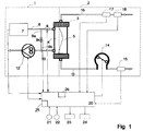
- FIG. 1 An exemplary embodiment of the invention is explained in more detail below with reference to the drawing, a hemodialysis device being shown in FIG.
- the hemodialysis device essentially consists of a dialysis fluid part 1 and an extracorporeal blood circuit part 2, between which there is a dialyzer 3 which is divided by a semipermeable membrane 39 into a dialysis fluid chamber 4 and a blood chamber 5.
- the dialysis fluid chamber 4 is connected upstream of the dialyzer 3 to a dialysis fluid source 7 via a dialysis fluid supply line 6.
- the feed line 6 also has an activated dialyzer valve 8.
- a drain line 10 leads from the dialysis fluid chamber 4, into which a dialysis fluid pump 12 is switched on.
- a by-pass line 9 extends from the supply line 6 to the drain line 10 between the dialysis fluid source 7 and the dialyzer valve 8. This by-pass line 9 is divided into the line sections 9a and 9b by the switched-on by-pass valve 9c.
- the extracorporeal blood circuit 2 has a blood supply line 13, into which a blood pump 14 is switched on. Upstream of this blood pump 14, the blood supply line 13 is connected to an arterial pressure sensor 15.
- a blood drain line 16 continues from the dialyzer 3, into which a venous pressure sensor 17 and an optical sensor 18 are switched on.
- Other commonly available devices such as drip chambers and shut-off clamps, are not shown in the drawing.
- the blood pump 14, the dialysis fluid pump 12, the dialysis fluid source 7, the dialyzer valve 8 and the by-pass valve 9c as well as the pressure sensors 15, 17 and the optical detector 18 are connected to a control unit 20 via corresponding electrical lines.
- This control unit 20 is furthermore equipped with an input unit 21 which enables the input of parameters, for example the inner tube diameter of the blood tube used and the tube type, serves and connected to a further input unit 22, with which the pumping rate of the blood pump can be predetermined.
- the control unit 20 also has display units 23 and 24 with which the effective blood flow or the accumulated blood volume can be displayed.
- the input unit 21 can have, for example, a switch device which enables the selection of a specific hose type, the inner diameter and the compliance behavior, that is to say the change in the cross section and the influence of the pressure present, being determinable at the same time.
- a barcode reader or another device can be used instead of such an input unit 21, which recognizes a marking connected to the tube, which is input into the control unit 20 and further processed there.
- the input unit 21 can also be designed as a device that determines the inner tube diameter.
- a device that determines the inner tube diameter.
- the hose inner diameter is determined with the aid of a force-displacement measuring device, from which a parameter proportional to the flexibility of the hose can be derived.
- an automatic adjustment can also take place, for example as a function of the pressure on the pressure sensor 15.
- the input unit can then be used to specify the target pressure.
- pressure control of the Blood pump is described for example in EP 0154681, to which reference is made.
- the control unit 20 also has a storage unit 25, in which data about the change in cross-section of different hose types under the influence of the upstream pressure are stored or can be stored.
- This data can either be in the form of a table or an equation.
- This table or equation yields a form factor, the value of which is zero at pressure and whose value becomes less than 1 for underpressures and greater than 1 for overpressures.
- This form factor is also included in the hose parameters.
- a typical value for a negative pressure of minus 100 mmHg is, for example, 0.9 for a typical hose made of silicone material with a nominal inner diameter of 8 mm, i.e. the cross-section changes by a factor of 0.9 at this negative pressure, which means that 10% less liquid is conveyed through the hose.
- the effective blood flow for a rotating peristaltic pump is determined by multiplying the speed of rotation of the pump (rpm) by the pump constant, which corresponds to the circumference of the pump tube axis (cm / rev), the nominal cross section of the tube, which is calculated from the inside diameter can (cm2) and the dimensionless form factor mentioned above, which takes the pressure dependence into account.
- the product of the dimensions given above consequently gives cm3 / min.
- This effective blood flow can be controlled by a integrate more facility over time.
- the integration begins at that moment when the optical sensor 18 registers the color change from light to dark, which indicates that blood is now being treated, whereas previously the tube system was previously only filled with physiological saline in a known manner.
- the integration is interrupted whenever the by-pass valve 9c is open or the dialyzer valve 8 is closed. This takes place in a known manner whenever the dialysis liquid has the wrong composition or the wrong temperature.
- the dialyzer valve 8 can also be closed for periodic recalibration or testing of devices of the dialysis fluid system.
- the above-mentioned input device 21 or a further input device can serve to record and enter the dialyzer type, the patient weight or the patient identifier.
- an additional storage device can also contain the whole body water or weight belonging to a specific patient identifier (name, number).
- the dialysis fluid flow (which can be determined by connecting the pump 12 to the control and evaluation unit 20) and the dialyzer data field thus calculate the clearance and integrate it over time, which gives kT. If, in addition, as mentioned, the patient's weight or the patient's whole body water is recorded, the size kT / V can be calculated and displayed on one of the mentioned display devices 23, 24.
- the end of dialysis can be forecast in advance or the achievement of the target value can be indicated by a suitable signal.
- the clearance measurement is repeated and the result is compared with the value from the corrected clearance performance field. If there is a difference that is greater than the measurement tolerance (typically +/- 5%), the clearance performance field is corrected and from then on integrated with the new clearance value.
- the measurement tolerance typically +/- 5%
- Peristaltic pumps are usually designed so that the pumping rate in the working area is independent of the pressure downstream of the pump. If, in exceptional cases, there is a dependency of the pumping rate on the pressure downstream of the pump for a specific pump type, the device according to the invention can also be used in this case.
- a further pressure sensor is provided downstream of the blood pump 14, the factor then being determined using a two-dimensional data field (pressure upstream, pressure downstream).
- the invention is not limited to rotating, peristaltic pumps, but rather can also be adapted to other pumps if their delivery rate depends on the pressure. Only the above-mentioned pump constant (nominal rate / number of revolutions) then has to be adapted accordingly to the pump design.
- the invention is not limited to dialysis devices, but rather can be used with all blood treatment devices in which there is a connection between the amount of blood pumped and the effectiveness of treatment.
- These include e.g. Devices for irradiating blood with light.
- the integration of the blood flow is then not interrupted by a by-pass line, as in the case of the interruption of the dialysis fluid flow, but - according to the treatment method - by interrupting the light irradiation.
- the device according to the invention is also suitable for hemofiltration or plasma filtration, but with these treatments the amount exchanged by filtration is advantageously used to assess the treatment effectiveness.
Abstract
Description
Die Erfindung betrifft ein Verfahren zur Bestimmung des effektiven Flusses einer Flüssigkeit sowie Vorrichtung zur Durchführung des Verfahrens gemäß dem Oberbegriff des Anspruchs 1 bzw. Anspruchs 4.The invention relates to a method for determining the effective flow of a liquid and device for carrying out the method according to the preamble of claim 1 and claim 4.
Die Behandlung der chronischen Niereninsuffizienz durch die Hämodialyse ist ein weitverbreitetes Verfahren, dem weltweit mehr als 300.000 Patienten das Überleben verdanken.The treatment of chronic renal failure by hemodialysis is a widespread procedure that has helped more than 300,000 patients worldwide to survive.
Die damit verbundenen Kosten sind für die Öffentlichkeit beachtlich, da die Patienten mit einem erheblichen Aufwand ca. 3 x pro Woche behandelt werden müssen.The associated costs are considerable for the public, since the patients have to be treated approximately 3 times a week with considerable effort.
Insofern wurde daher bereits seit längerem die Frage gestellt, welche "Behandlungsdosis" notwendig bzw. hinreichend ist.In this respect, the question of which "treatment dose" is necessary or sufficient has long been asked.
In der sogenannten "National Cooperative Dialysis Study", die in der ersten Hälfte der 80-er Jahre in den USA durchgeführt worden ist, hat man diese Frage an einer größeren Anzahl von Patienten unter gezielten Randbedingungen untersucht.In the so-called "National Cooperative Dialysis Study", which was carried out in the USA in the first half of the 1980s, this question was examined in a large number of patients under specific boundary conditions.
Die von Gotch und Sargent (F.A. Gotch, J.A. Sargent:
A mechanistic analysis of the National Cooperative Dialysis Study NCDS), Kidney International 28, Seite 526-534 (1985) durchgeführte Interpretation der Ergebnisse ist heute weitgehend anerkannt. Gotch und Sargent kommen zu dem Schluß, daß bei einer dreimaligen Behandlung pro Woche eine hinreichende Behandlungsqualität erzielt wird, wenn das Produkt aus Clearance x Behandlungszeit dem Ganzkörperwasservolumen des Patienten entspricht:
![]()
A mechanistic analysis of the National Cooperative Dialysis Study NCDS), Kidney International 28, pages 526-534 (1985) is widely recognized today. Gotch and Sargent conclude that treatment three times a week provides adequate treatment quality if the product of clearance x treatment time is the same Whole body water volume of the patient corresponds to:
![]()
In der Praxis sollen nun die Behandlungsparameter so vorgeschrieben und kontrolliert werden, daß dieses Behandlungsziel erreicht wird. Das kann beispielsweise so erfolgen, daß die Harnstoffclearenace, die mit dem vorgeschriebenen Blutfluß erzielt wird, für einen bestimmten Dialysator aus der Tabelle des Dialysator-Herstellers entnommen und das Ganzkörperwasservolumen des Patienten dadurch geteilt wird. Hieraus erhält man dann die notwendige Behandlungszeit. Das Ganzkörperwasservolumen kann dabei entweder mit Hilfe bekannter Verfahren oder näherungsweise mit 60 % des Körpergewichts angenommen werden.In practice, the treatment parameters should now be prescribed and controlled so that this treatment goal is achieved. This can be done, for example, by taking the urea clearenace that is achieved with the prescribed blood flow for a particular dialyzer from the table of the dialyzer manufacturer and thereby dividing the patient's whole body water volume. From this you get the necessary treatment time. The whole body water volume can be assumed either using known methods or approximately 60% of the body weight.
Die Harnstoffclearance selbst ergibt sich bei einem bestimmten Dialysator und vorgegebenem Dialysierflüssigkeitsfluß aus dem Blutfluß. Multipliziert man den Blutfluß mit der oben errechneten Zeit, so erhält man das Blutvolumen. In guter Näherung kann man davon ausgehen, daß das Behandlungsziel erreicht wurde, wenn das so errechnete Blutvolumen durch den Dialysator gepumpt worden ist.The urea clearance itself results from the blood flow for a certain dialyzer and a given dialysis fluid flow. Multiplying the blood flow by the time calculated above gives the blood volume. To a good approximation, it can be assumed that the treatment goal has been achieved when the blood volume calculated in this way has been pumped through the dialyzer.
Nachdem die Behandlungszeit in den letzten 10 Jahren von durchschnittlich 6 auf durchschnittlich 3 Stunden verkürzt worden ist, wirken sich Einflüsse, die den Blutfluß während der Behandlungszeit temporär verringern, nunmehr relativ stärker auf die Effektivität der Dialyse aus.After the treatment time has been reduced from an average of 6 hours to an average of 3 hours in the last 10 years, influences that temporarily reduce the blood flow during the treatment time are now having a relatively greater effect on the effectiveness of dialysis.
Insofern soll das behandelte Blut bei der Hömodialyse möglichst genau erfaßt werden.In this respect, the blood treated during homemodialysis should be recorded as precisely as possible.
Das Blut wird heute nahezu ausschließlich mit Hilfe von peristaltischen Schlauchpumpen im extrakorporalen Kreislauf gefördert. Aus der DE-OS 25 35 650 läßt sich entnehmen, wie aus dem Innendurchmesser des Pumpenschlauchs und der Pumpendrehzahl die Förderrate der Pumpe errechnet und angezeigt werden kann.Today, the blood is almost exclusively pumped with the help of peristaltic peristaltic pumps in the extracorporeal circuit. From DE-OS 25 35 650 it can be seen how the pump delivery rate can be calculated and displayed from the inside diameter of the pump hose and the pump speed.
Diese Förderrate kann nun über die Zeit integriert werden, wobei man als Resultat ein Blutvolumen erhält. Ein solches ist mit der Pumpe, die von der Anmelderin für die Hämodiafiltration mit ihren Hämodialysegeräten A2008D bzw. A2008E anbietet, möglich. Wird bei dieser Pumpe der Fluß unterbrochen, so wird auch die Volumenzählung unterbrochen.This delivery rate can now be integrated over time, resulting in a blood volume. This is possible with the pump that the applicant offers for hemodiafiltration with its A2008D or A2008E hemodialysis machines. If the flow is interrupted with this pump, the volume count is also interrupted.
Obwohl dabei bereits ein Fortschritt bei der Beurteilung der Effektivität der Hämodialyse erzielt worden ist, stimmt das ermittelte Blutvolumen immer noch nicht mit dem tatsächlich geförderten Blutvolumen überein.Although progress has been made in assessing the effectiveness of hemodialysis, the blood volume determined still does not match the blood volume actually delivered.
Der Erfindung liegt daher die Aufgabe zugrunde, das Verfahren und die Vorrichtung der eingangs erwähnten Art so zu verbessern, daß das errechnete Flüssigkeitsvolumen im wesentlichen mit dem tatsächlich geförderten Flüssigkeitsvolumen, insbesondere dem Blutvolumen übereinstimmt.The invention is therefore based on the object of improving the method and the device of the type mentioned at the outset in such a way that the calculated volume of liquid essentially corresponds to the actually pumped liquid volume, in particular the blood volume.
Die Lösung der Aufgabe erfolgt durch die kennzeichnenden Merkmale des Anspruchs 1 bzw. Anspruchs 4.The object is achieved by the characterizing features of claim 1 and claim 4.
Durch die Lehre der Erfindung wird die Förderrate des Schlauchs um einen bestimmten Formfaktor korrigiert, der für jede Schlauchart spezifisch ist. Bekanntlich kollabieren Schläuche von peristaltischen Pumpen unter dem Einfluß des Ansaugunterdrucks, wodurch der effektive Pumpquerschnitt und damit die Pumprate heruntergesetzt werden. Dabei ist die Verformung des Schlauchs vom Druck abhängig, d.h. das Schlauchmaterial, die Dicke der Schlauchwand, die Temperatur der zu fördernden Flüssigkeit und dergleichen bestimmen die Steifigkeit des Materials und damit auch die Verformbarkeit. Werden da nun diese Parameter in einer Tabelle in Abhängigkeit vom Druck berücksichtigt, so kann ein derart ermittelter Formfaktor zur Korrektur des Pumpvolumens herangezogen werden.Through the teaching of the invention, the delivery rate of the hose by a certain form factor corrected, which is specific for each hose type. As is known, hoses of peristaltic pumps collapse under the influence of the suction vacuum, as a result of which the effective pump cross section and thus the pumping rate are reduced. The deformation of the hose is dependent on the pressure, ie the hose material, the thickness of the hose wall, the temperature of the liquid to be conveyed and the like determine the rigidity of the material and thus also the deformability. If these parameters are now taken into account in a table as a function of the pressure, a form factor determined in this way can be used to correct the pump volume.
Ausgestaltungen des Verfahrens und der Vorrichtung sind in den Unteransprüchen angegeben.Embodiments of the method and the device are specified in the subclaims.
Nachfolgend wird ein Ausführungsbeispiel der Erfindung anhand der Zeichnung näher erläutert, wobei in der Figur 1 eine Hämodialysevorrichtung dargestellt ist.An exemplary embodiment of the invention is explained in more detail below with reference to the drawing, a hemodialysis device being shown in FIG.
Die Hömodialysevorrichtung besteht im wesentlichen aus einem Dialysierflüssigkeitsteil 1 und einem extrakorporalen Blutkreislaufteil 2, zwischen denen sich ein Dialysator 3 befindet, der durch eine semipermeable Membran 39 in eine Dialysierflüssigkeitskammer 4 und eine Blutkammer 5 geteilt ist. Die Dialysierflüssigkeitskammer 4 ist stromauf des Dialysators 3 über eine Dialysierflüssigkeitszuleitung 6 mit einer Dialysierflüssigkeitsquelle 7 verbunden. Die Zuleitung 6 weist weiterhin ein eingeschaltetes Dialysatorventil 8 auf.The hemodialysis device essentially consists of a dialysis fluid part 1 and an extracorporeal
Stromab des Dialysators 3 geht von der Dialysierflüssigkeitskammer 4 eine Abflußleitung 10 ab, in die eine Dialysierflüssigkeitspumpe 12 eingeschaltet ist. Zwischen der Dialysierflüssigkeitsquelle 7 und dem Dialysatorventil 8 erstreckt sich eine By-pass-Leitung 9 von der Zuleitung 6 zur Abflußleitung 10. Diese By-pass-Leitung 9 ist in die Leitungsabschnitte 9a und 9b durch das eingeschaltete By-pass-Ventil 9c geteilt.Downstream of the
Der extrakorporale Blutkreislauf 2 weist eine Blutzuführungsleitung 13 auf, in die eine Blutpumpe 14 eingeschaltet ist. Stromauf dieser Blutpumpe 14 ist die Blutzuführungsleitung 13 mit einem arteriellen Drucksensor 15 verbunden.The
Vom Dialysator 3 geht weiterhin eine Blutabflußleitung 16 ab, in die ein venöser Drucksensor 17 und ein optischer Sensor 18 eingeschaltet sind. Weitere üblicherweise vorhandenen Einrichtungen, wie Tropfkammern und Absperrklemmen, sind in der Zeichnung nicht dargestellt.A
Die Blutpumpe 14, die Dialysierflüssigkeitspumpe 12, die Dialysierflüssigkeitsquelle 7, das Dialysatorventil 8 und das By-pass-Ventil 9c sowie die Drucksensoren 15, 17 und der optische Detektor 18 sind über entsprechende elektrische Leitungen mit einer Steuereinheit 20 verbunden.The
Diese Steuereinheit 20 ist fernerhin mit einer Eingabeeinheit 21, die der Eingabe von Parametern, beispielsweise des Schlauchinnendurchmessers des eingesetzten Blutschlauchs und des Schlauchtyps, dient und mit einer weiteren Eingabeeinheit 22 verbunden, mit der die Pumprate der Blutpumpe vorbestimmt werden kann. Die Steuereinheit 20 verfügt weiterhin über Anzeigeeinheiten 23 und 24, mit denen der effektive Blutfluß oder das kumulierte Blutvolumen angezeigt werden können.This
Die Eingabeeinheit 21 kann beispielsweise eine Schaltereinrichtung aufweisen, die die Wahl eines bestimmten Schlauchtyps ermöglicht, wobei gleichzeitig der Innendurchmesser und das Complianceverhalten, also die Veränderung des Querschnitts und der Einfluß des anliegenden Drucks bestimmbar sind. Andererseits können jedoch auch anstelle einer solchen Eingabeeinheit 21 ein Barcodeleser oder eine andere Vorrichtung eingesetzt werden, die eine mit dem Schlauch verbundene Markierung erkennt, die in die Steuereinheit 20 eingegeben und dort weiterverarbeitet wird.The
Die Eingabeeinheit 21 kann auch als eine Vorrichtung ausgebildet sein, die den Schlauchinnendurchmesser ermittelt. Eine solche Vorrichtung ist in der DE-OS 38 42 404 beschrieben, auf deren Offenbarung Bezug genommen wird. Gemäß dieser bekannten Vorrichtung wird mit Hilfe einer Kraft-Weg-Meßeinrichtung der Schlauchinnendurchmesser bestimmt, wobei sich hieraus ein der Nachgiebigkeit des Schlauchs proportionaler Parameter ableiten läßt.The
Anstelle einer manuellen Einstellung des Blutflusses über die Eingabeeinheit 22 kann auch eine selbsttätige Einstellung, beispielsweise als Funktion des Drucks am Drucksensor 15 erfolgen. Die Eingabeeinheit kann dann zur Vorgabe des Solldrucks verwendet werden. Eine solche Drucksteuerung der Blutpumpe ist beispielsweise in der EP 0154681 beschrieben, auf die Bezug genommen wird.Instead of manual adjustment of the blood flow via the
Die Steuereinheit 20 weist ferner eine Speichereinheit 25 auf, in die Daten über die Querschnittsveränderung unterschiedlicher Schlauchtypen unter Einfluß des stromauf anliegenden Drucks gespeichert sind bzw. speicherbar sind. Diese Daten können entweder in Form einer Tabelle oder einer Gleichung vorliegen. Diese Tabelle bzw. Gleichung ergibt einen Formfaktor, dessen Wert beim Druck null 1 ist und dessen Wert für Unterdrucke kleiner 1 und für Überdrucke größer 1 wird. Dieser Formfaktor ist ebenfalls zu den Schlauchparametern zu rechnen. Ein typischer Wert für einen Unterdruck von minus 100 mmHg ist beispielsweise 0,9 für einen typischen Schlauch aus Siliconmaterial mit einem nominalen Innendurchmesser von 8 mm, d.h. der Querschnitt verändert sich um den Faktor 0,9 bei diesem Unterdruck, was zur Folge hat, daß 10 % weniger Flüssigkeit durch den Schlauch gefördert werden.The
Die Ermittlung des effektiven Blutflusses für eine rotierende peristaltische Pumpe erfolgt durch die Multiplikation der Umdrehungsgeschwindigkeit der Pumpe (U/min) mit der Pumpkonstante, die dem Umfang der Pumpschlauchachse entspricht (cm/U), dem Nominalquerschnitt des Schlauchs, der aus dem Innendurchmesser berechnet werden kann (cm²) und dem oben erwähnten dimensionslosen Formfaktor, der die Druckabhängigkeit berücksichtigt. Das Produkt der oben angegebenen Dimensionen ergibt folgerichtig cm³/min.The effective blood flow for a rotating peristaltic pump is determined by multiplying the speed of rotation of the pump (rpm) by the pump constant, which corresponds to the circumference of the pump tube axis (cm / rev), the nominal cross section of the tube, which is calculated from the inside diameter can (cm²) and the dimensionless form factor mentioned above, which takes the pressure dependence into account. The product of the dimensions given above consequently gives cm³ / min.
Dieser effektive Blutfluß läßt sich durch eine weitere Einrichtung über die Zeit integrieren. Die Integration beginnt in jenem Moment, da der optische Sensor 18 den Farbumschlag von hell auf dunkel registriert, womit angezeigt wird, daß nunmehr Blut behandelt wird, während zuvor das Schlauchsystem in bekannter Weise lediglich mit physiologischer Kochsalzlösung vorgefüllt war. Die Integration wird immer dann unterbrochen, wenn das By-pass-Ventil 9c geöffnet oder das Dialysatorventil 8 geschlossen ist. Dies erfolgt in bekannter Weise immer dann, wenn die Dialysierflüssigkeit eine falsche Zusammensetzung oder eine falsche Temperatur besitzt. Andererseits kann auch das Dialysatorventil 8 zur periodischen Rekalibrierung oder Prüfung von Einrichtungen des Dialysierflüssigkeitssystems geschlossen werden.This effective blood flow can be controlled by a integrate more facility over time. The integration begins at that moment when the
In einer weiteren Ausgestaltung der Erfindung kann die oben erwähnte Eingabeeinrichtung 21 oder eine weitere Eingabeeinrichtung dazu dienen, den Dialysatortyp, das Patientengewicht oder das Patientenkennzeichen zu erfassen und einzugeben.In a further embodiment of the invention, the above-mentioned
In einer weiteren Speichereinrichtung 26 wird vorteilhaft das Datenfeld Clearance/Blutfluß und der Dialysierflüssigkeitsfluß für verschiedene Dialysatortypen gespeichert. Darüber hinaus kann eine zusätzliche Speichereinrichtung auch noch das, zu einem bestimmten Patientenkennzeichen (Name, Nummer) gehörende Ganzkörperwasser oder Gewicht enthalten.The data field clearance / blood flow and the dialysis fluid flow for various types of dialyzer are advantageously stored in a
Aus dem effektiven Blutfluß, dem Dialysierflüssigkeitsfluß (der durch die Verbindung der Pumpe 12 mit der Steuer- und Auswerteeinheit 20 erfaßbar ist) und dem Dialysatordatenfeld läßt sich somit die Clearance errechnen und diese über die Zeit integrieren, womit man k.T erhält. Wird zusätzlich, wie erwähnt, daß Patientengewicht bzw. das Patientenganzkörperwasser erfaßt, so läßt sich die Größe kT/V errechnen und über eine der erwähnten Anzeigevorrichtungen 23,24 darstellen.From the effective blood flow, the dialysis fluid flow (which can be determined by connecting the
Mit Hilfe des Verlaufs dieser Größen und durch Vergleich mit einem vorgegebenen Sollwert läßt sich beispielsweise das Dialyseende vorausschauend hochrechnen oder das Erreichen des Sollwerts durch ein geeignetes Signal angeben.With the aid of the course of these variables and by comparison with a predetermined target value, for example, the end of dialysis can be forecast in advance or the achievement of the target value can be indicated by a suitable signal.
Aus der DE-OS 39 38 662 ist die Bestimmung der Harnstoffclearance während der Hämodialyse mit Hilfe einer Leitfähigkeitsrelativmessung bekannt. Diese Bestimmung läß sich mit der vorliegenden Anordnung gemäß Figur 1 folgendermaßen kombinieren. Zu Beginn der Hämodialyse wird die Clearance bestimmt und das Resultat zur Korrektur des gespeicherten Clearance-Leistungsfelds (Clearance gegen Blut- und Dialysierflüssigkeitsfluß) bzw. der gespeicherten Clearanceformel verwendet. Die kumulierte Größe k.T wird dann erfindungsgemäß, wie weiter oben beschrieben, bestimmt.From DE-OS 39 38 662 the determination of the urea clearance during hemodialysis with the aid of a conductivity measurement is known. This determination can be combined with the present arrangement according to FIG. 1 as follows. At the beginning of hemodialysis, the clearance is determined and the result is used to correct the stored clearance performance field (clearance against blood and dialysis fluid flow) or the stored clearance formula. The accumulated size k.T is then determined according to the invention as described above.
Im Laufe der Dialyse (beispielsweise nach einer Stunde) wird die Clearancemessung wiederholt und das Resultat mit dem Wert aus dem korrigierten Clearanceleistungsfeld verglichen. Bei einer Differenz, die größer als die Meßtoleranz (typisch +/- 5 %) ist, wird das Clearanceleistungsfeld korrigiert und von da an mit dem neuen Clearancewert integriert.In the course of dialysis (for example after one hour), the clearance measurement is repeated and the result is compared with the value from the corrected clearance performance field. If there is a difference that is greater than the measurement tolerance (typically +/- 5%), the clearance performance field is corrected and from then on integrated with the new clearance value.
Üblicherweise sind peristaltisch arbeitende Pumpen so ausgelegt, daß die Pumprate im Arbeitsbereich unabhängig vom Druck stromab der Pumpe ist. Sollte im Ausnahmefall doch eine Abhängigkeit der Pumprate vom Druck stromab der Pumpe bei einem bestimmten Pumptyp vorliegen, so läßt sich die erfindungsgemäße Einrichtung ebenfalls auf diesen Fall anwenden. Dabei wird ein weiterer Drucksensor stromab der Blutpumpe 14 vorgesehen, wobei der Faktor dann über ein zweidimensionales Datenfeld (Druck stromauf, Druck stromab) ermittelt wird.Peristaltic pumps are usually designed so that the pumping rate in the working area is independent of the pressure downstream of the pump. If, in exceptional cases, there is a dependency of the pumping rate on the pressure downstream of the pump for a specific pump type, the device according to the invention can also be used in this case. A further pressure sensor is provided downstream of the
Andererseits ist die Erfindung nicht auf rotierende, peristaltisch arbeitende Pumpen beschränkt, sondern vielmehr unangepaßt auch auf andere Pumpen anwendbar, wenn deren Förderrate vom Druck abhängt. Lediglich die oben erwähnte Pumpenkonstante (Nominalrate/Undrehungszahl) muß dann der Pumpenkonstruktion entsprechend angepaßt werden.On the other hand, the invention is not limited to rotating, peristaltic pumps, but rather can also be adapted to other pumps if their delivery rate depends on the pressure. Only the above-mentioned pump constant (nominal rate / number of revolutions) then has to be adapted accordingly to the pump design.
Die Erfindung ist ferner nicht auf Dialysevorrichtungen beschränkt, sondern vielmehr bei allen Blutbehandlungseinrichtungen anwendbar, bei denen ein Zusammenhang zwischen gepumpter Blutmenge und Behandlungseffektivität besteht. Dazu gehören z.B. Einrichtungen zur Bestrahlung von Blut mit Licht. Die Unterbrechung der Integration des Blutflusses erfolgt dann nicht, wie bei der Unterbrechung des Dialysierflüssigkeitsflusses, durch eine By-pass-Leitung, sondern - der Behandlungsmethode entsprechend - durch Unterbrechung der Lichtbestrahlung.Furthermore, the invention is not limited to dialysis devices, but rather can be used with all blood treatment devices in which there is a connection between the amount of blood pumped and the effectiveness of treatment. These include e.g. Devices for irradiating blood with light. The integration of the blood flow is then not interrupted by a by-pass line, as in the case of the interruption of the dialysis fluid flow, but - according to the treatment method - by interrupting the light irradiation.
Grundsätzlich ist die erfindungsgemäße Vorrichtung auch für die Hämo- oder Plasmafiltration geeignet, wobei jedoch bei diesen Behandlungen vorteilhafterweise die durch Filtration ausgetauschte Menge zur Beurteilung der Behandlungseffektivität herangezogen wird.In principle, the device according to the invention is also suitable for hemofiltration or plasma filtration, but with these treatments the amount exchanged by filtration is advantageously used to assess the treatment effectiveness.
Bei der Hämodiafiltration (Kombination von Hämofiltration und Hämodialyse) ist schließlich eine Kombination der beiden Beurteilungsverfahren (Blutvolumen und Austauschvolumen) vorteilhaft.In hemodiafiltration (combination of hemofiltration and hemodialysis), a combination of the two assessment methods (blood volume and exchange volume) is ultimately advantageous.
Claims (10)
Priority Applications (1)
| Application Number | Priority Date | Filing Date | Title |
|---|---|---|---|
| EP91108005A EP0513421A1 (en) | 1991-05-17 | 1991-05-17 | Device for measuring the volume of blood treated during haemodialysis |
Applications Claiming Priority (1)
| Application Number | Priority Date | Filing Date | Title |
|---|---|---|---|
| EP91108005A EP0513421A1 (en) | 1991-05-17 | 1991-05-17 | Device for measuring the volume of blood treated during haemodialysis |
Publications (1)
| Publication Number | Publication Date |
|---|---|
| EP0513421A1 true EP0513421A1 (en) | 1992-11-19 |
Family
ID=8206734
Family Applications (1)
| Application Number | Title | Priority Date | Filing Date |
|---|---|---|---|
| EP91108005A Withdrawn EP0513421A1 (en) | 1991-05-17 | 1991-05-17 | Device for measuring the volume of blood treated during haemodialysis |
Country Status (1)
| Country | Link |
|---|---|
| EP (1) | EP0513421A1 (en) |
Cited By (5)
| Publication number | Priority date | Publication date | Assignee | Title |
|---|---|---|---|---|
| DE19801768A1 (en) * | 1998-01-19 | 1999-07-29 | Fresenius Medical Care De Gmbh | Method and device for providing operational dialysis fluid |
| DE102006032926A1 (en) * | 2006-07-15 | 2008-01-17 | Fresenius Medical Care Deutschland Gmbh | Method and device for prescribing treatment parameters for extracorporeal dialysis treatments |
| DE102010002133A1 (en) * | 2010-02-18 | 2011-08-18 | Fresenius Medical Care Deutschland GmbH, 61352 | Safety device for a hose roller pump |
| WO2015110437A1 (en) * | 2014-01-22 | 2015-07-30 | Fresenius Medical Care Deutschland Gmbh | Device and method for regulating and specifying the pump rate of blood pumps |
| EP3031485B1 (en) | 2014-12-10 | 2018-11-21 | B. Braun Avitum AG | Method and control apparatus for determining and adjusting a flow rate of a blood delivery pump |
Citations (3)
| Publication number | Priority date | Publication date | Assignee | Title |
|---|---|---|---|---|
| DE3842404A1 (en) * | 1988-12-16 | 1990-06-21 | Fresenius Ag | DEVICE FOR MEASURING THE INTERNAL DIAMETER OF HOSES MADE OF FLEXIBLE MATERIAL |
| EP0393354A1 (en) * | 1989-04-15 | 1990-10-24 | B. Braun Melsungen AG | Medical pump appliance |
| WO1991009229A1 (en) * | 1989-12-14 | 1991-06-27 | Baxter International Inc. | Accurate peristaltic pump |
-
1991
- 1991-05-17 EP EP91108005A patent/EP0513421A1/en not_active Withdrawn
Patent Citations (3)
| Publication number | Priority date | Publication date | Assignee | Title |
|---|---|---|---|---|
| DE3842404A1 (en) * | 1988-12-16 | 1990-06-21 | Fresenius Ag | DEVICE FOR MEASURING THE INTERNAL DIAMETER OF HOSES MADE OF FLEXIBLE MATERIAL |
| EP0393354A1 (en) * | 1989-04-15 | 1990-10-24 | B. Braun Melsungen AG | Medical pump appliance |
| WO1991009229A1 (en) * | 1989-12-14 | 1991-06-27 | Baxter International Inc. | Accurate peristaltic pump |
Cited By (9)
| Publication number | Priority date | Publication date | Assignee | Title |
|---|---|---|---|---|
| DE19801768A1 (en) * | 1998-01-19 | 1999-07-29 | Fresenius Medical Care De Gmbh | Method and device for providing operational dialysis fluid |
| DE19801768C2 (en) * | 1998-01-19 | 2001-04-19 | Fresenius Medical Care De Gmbh | Method and device for providing operational dialysis fluid |
| DE102006032926A1 (en) * | 2006-07-15 | 2008-01-17 | Fresenius Medical Care Deutschland Gmbh | Method and device for prescribing treatment parameters for extracorporeal dialysis treatments |
| DE102010002133A1 (en) * | 2010-02-18 | 2011-08-18 | Fresenius Medical Care Deutschland GmbH, 61352 | Safety device for a hose roller pump |
| DE102010002133B4 (en) * | 2010-02-18 | 2015-11-12 | Fresenius Medical Care Deutschland Gmbh | Safety device for a hose roller pump |
| WO2015110437A1 (en) * | 2014-01-22 | 2015-07-30 | Fresenius Medical Care Deutschland Gmbh | Device and method for regulating and specifying the pump rate of blood pumps |
| US10702643B2 (en) | 2014-01-22 | 2020-07-07 | Fresenius Medical Care Deutschland Gmbh | Device and method for regulating and presetting the pump rate of blood pumps |
| EP3031485B1 (en) | 2014-12-10 | 2018-11-21 | B. Braun Avitum AG | Method and control apparatus for determining and adjusting a flow rate of a blood delivery pump |
| US10610632B2 (en) | 2014-12-10 | 2020-04-07 | B. Braun Avitum Ag | Method and control apparatus for determining and adjusting a flow rate of a blood delivery pump |
Similar Documents
| Publication | Publication Date | Title |
|---|---|---|
| EP1859168B1 (en) | Method and device for determining the effective delivery rate or for adjusting the speed of a peristaltic pump | |
| DE19821534C1 (en) | Blood cleaning machine | |
| EP1539271B1 (en) | Blood treatment device for returning blood | |
| EP1020199B1 (en) | Device for the detection of stenosis during extracorporal blood treatment | |
| EP1348457B1 (en) | Method of determining of a treatment parameter on a hemofiltration apparatus and hemodialysis apparatus therefor | |
| DE69827338T2 (en) | Device for monitoring an infusion pump | |
| DE19746367C2 (en) | Method for in-vivo determination of parameters of hemodialysis and device for carrying out the method | |
| EP0373455B1 (en) | Device for continuous hemofiltration and hemodiafiltration | |
| EP2714128B1 (en) | Device and method for recognizing an operating state of an extra-corporeal blood treatment | |
| EP3034110B1 (en) | Method and device for determining the transmembrane pressure in an extracorporeal blood treatment | |
| EP0687474A1 (en) | Apparatus for peritoneal dialysis | |
| EP0720856A2 (en) | Device for on-line cleaning and filling of an extracorporal blood circuit of a dialysis apparatus | |
| EP2736561B1 (en) | Method and devices for detaching gas accumulations from a blood clot catcher of an extracorporeal blood circulation | |
| EP0161686B1 (en) | Method for filling the blood tubing system of a hemodialysing device with a saline solution | |
| DE102016117725A1 (en) | A method for removing blood from an extracorporeal blood circulation after completion of a blood treatment session, control and regulation device and treatment device for performing the same | |
| EP3955988B1 (en) | Recirculation measurement by means of diffusion equilibrium | |
| EP0513421A1 (en) | Device for measuring the volume of blood treated during haemodialysis | |
| EP3820542A1 (en) | Control and/or regulating device for removing fluid from a blood filter | |
| DE4116178C1 (en) | ||
| DE10245619B4 (en) | Method for returning blood from a blood treatment device and device for carrying out the method | |
| EP4213908A1 (en) | Method for identifying the type of a medical filter, and devices | |
| DE2629717C2 (en) | Device for controlling the fluid balance of a patient during hemodiafiltration | |
| DE102020122937A1 (en) | Automated priming and flushing of an extracorporeal blood treatment device | |
| EP3797805B1 (en) | Blood treatment device with automatic air removal |
Legal Events
| Date | Code | Title | Description |
|---|---|---|---|
| PUAI | Public reference made under article 153(3) epc to a published international application that has entered the european phase |
Free format text: ORIGINAL CODE: 0009012 |
|
| AK | Designated contracting states |
Kind code of ref document: A1 Designated state(s): DE ES FR GB IT SE |
|
| 17P | Request for examination filed |
Effective date: 19921228 |
|
| 17Q | First examination report despatched |
Effective date: 19940121 |
|
| STAA | Information on the status of an ep patent application or granted ep patent |
Free format text: STATUS: THE APPLICATION HAS BEEN WITHDRAWN |
|
| 18W | Application withdrawn |
Withdrawal date: 19940503 |