EP0513151B1 - Automatic spraygun with an indexing air cap - Google Patents
Automatic spraygun with an indexing air cap Download PDFInfo
- Publication number
- EP0513151B1 EP0513151B1 EP91903845A EP91903845A EP0513151B1 EP 0513151 B1 EP0513151 B1 EP 0513151B1 EP 91903845 A EP91903845 A EP 91903845A EP 91903845 A EP91903845 A EP 91903845A EP 0513151 B1 EP0513151 B1 EP 0513151B1
- Authority
- EP
- European Patent Office
- Prior art keywords
- spraygun
- air cap
- baffle
- collars
- seal
- Prior art date
- Legal status (The legal status is an assumption and is not a legal conclusion. Google has not performed a legal analysis and makes no representation as to the accuracy of the status listed.)
- Revoked
Links
Images

Classifications
-
- B—PERFORMING OPERATIONS; TRANSPORTING
- B05—SPRAYING OR ATOMISING IN GENERAL; APPLYING FLUENT MATERIALS TO SURFACES, IN GENERAL
- B05B—SPRAYING APPARATUS; ATOMISING APPARATUS; NOZZLES
- B05B7/00—Spraying apparatus for discharge of liquids or other fluent materials from two or more sources, e.g. of liquid and air, of powder and gas
- B05B7/02—Spray pistols; Apparatus for discharge
- B05B7/08—Spray pistols; Apparatus for discharge with separate outlet orifices, e.g. to form parallel jets, i.e. the axis of the jets being parallel, to form intersecting jets, i.e. the axis of the jets converging but not necessarily intersecting at a point
- B05B7/0807—Spray pistols; Apparatus for discharge with separate outlet orifices, e.g. to form parallel jets, i.e. the axis of the jets being parallel, to form intersecting jets, i.e. the axis of the jets converging but not necessarily intersecting at a point to form intersecting jets
- B05B7/0815—Spray pistols; Apparatus for discharge with separate outlet orifices, e.g. to form parallel jets, i.e. the axis of the jets being parallel, to form intersecting jets, i.e. the axis of the jets converging but not necessarily intersecting at a point to form intersecting jets with at least one gas jet intersecting a jet constituted by a liquid or a mixture containing a liquid for controlling the shape of the latter
- B05B7/083—Spray pistols; Apparatus for discharge with separate outlet orifices, e.g. to form parallel jets, i.e. the axis of the jets being parallel, to form intersecting jets, i.e. the axis of the jets converging but not necessarily intersecting at a point to form intersecting jets with at least one gas jet intersecting a jet constituted by a liquid or a mixture containing a liquid for controlling the shape of the latter comprising rotatable spray shaping gas jet outlets
-
- B—PERFORMING OPERATIONS; TRANSPORTING
- B05—SPRAYING OR ATOMISING IN GENERAL; APPLYING FLUENT MATERIALS TO SURFACES, IN GENERAL
- B05B—SPRAYING APPARATUS; ATOMISING APPARATUS; NOZZLES
- B05B13/00—Machines or plants for applying liquids or other fluent materials to surfaces of objects or other work by spraying, not covered by groups B05B1/00 - B05B11/00
- B05B13/02—Means for supporting work; Arrangement or mounting of spray heads; Adaptation or arrangement of means for feeding work
- B05B13/0278—Arrangement or mounting of spray heads
-
- B—PERFORMING OPERATIONS; TRANSPORTING
- B05—SPRAYING OR ATOMISING IN GENERAL; APPLYING FLUENT MATERIALS TO SURFACES, IN GENERAL
- B05B—SPRAYING APPARATUS; ATOMISING APPARATUS; NOZZLES
- B05B15/00—Details of spraying plant or spraying apparatus not otherwise provided for; Accessories
- B05B15/60—Arrangements for mounting, supporting or holding spraying apparatus
-
- B—PERFORMING OPERATIONS; TRANSPORTING
- B05—SPRAYING OR ATOMISING IN GENERAL; APPLYING FLUENT MATERIALS TO SURFACES, IN GENERAL
- B05B—SPRAYING APPARATUS; ATOMISING APPARATUS; NOZZLES
- B05B15/00—Details of spraying plant or spraying apparatus not otherwise provided for; Accessories
- B05B15/60—Arrangements for mounting, supporting or holding spraying apparatus
- B05B15/68—Arrangements for adjusting the position of spray heads
-
- B—PERFORMING OPERATIONS; TRANSPORTING
- B05—SPRAYING OR ATOMISING IN GENERAL; APPLYING FLUENT MATERIALS TO SURFACES, IN GENERAL
- B05B—SPRAYING APPARATUS; ATOMISING APPARATUS; NOZZLES
- B05B7/00—Spraying apparatus for discharge of liquids or other fluent materials from two or more sources, e.g. of liquid and air, of powder and gas
- B05B7/02—Spray pistols; Apparatus for discharge
- B05B7/08—Spray pistols; Apparatus for discharge with separate outlet orifices, e.g. to form parallel jets, i.e. the axis of the jets being parallel, to form intersecting jets, i.e. the axis of the jets converging but not necessarily intersecting at a point
- B05B7/0807—Spray pistols; Apparatus for discharge with separate outlet orifices, e.g. to form parallel jets, i.e. the axis of the jets being parallel, to form intersecting jets, i.e. the axis of the jets converging but not necessarily intersecting at a point to form intersecting jets
- B05B7/0815—Spray pistols; Apparatus for discharge with separate outlet orifices, e.g. to form parallel jets, i.e. the axis of the jets being parallel, to form intersecting jets, i.e. the axis of the jets converging but not necessarily intersecting at a point to form intersecting jets with at least one gas jet intersecting a jet constituted by a liquid or a mixture containing a liquid for controlling the shape of the latter
-
- Y—GENERAL TAGGING OF NEW TECHNOLOGICAL DEVELOPMENTS; GENERAL TAGGING OF CROSS-SECTIONAL TECHNOLOGIES SPANNING OVER SEVERAL SECTIONS OF THE IPC; TECHNICAL SUBJECTS COVERED BY FORMER USPC CROSS-REFERENCE ART COLLECTIONS [XRACs] AND DIGESTS
- Y10—TECHNICAL SUBJECTS COVERED BY FORMER USPC
- Y10T—TECHNICAL SUBJECTS COVERED BY FORMER US CLASSIFICATION
- Y10T403/00—Joints and connections
- Y10T403/70—Interfitted members
- Y10T403/7075—Interfitted members including discrete retainer
Definitions
- This invention relates to an indexing air cap for automatic sprayguns.
- Automatic sprayguns are increasingly being used in spray booths to spray e.g. paint on the bodywork of motor vehicles.
- the accuracy of mounting the spraygun on a robot has become critical as the centre of the area to be sprayed must be located within 2 mm to 5 mm of the centre axis of the spraygun nozzle when repositioning the spraygun.
- Manually operated sprayguns do not have the same disadvantage as the positioning of the spraygun is made by the eye of an experienced operator which prevents this problem.
- Indexing air caps for manually operated sprayguns are known from documents FR-A-2 527 480 and US-A-1 717 086.
- An aim of the present invention is to overcome or mitigate the above mentioned disadvantage of automatic sprayguns.
- an automatic spraygun comprising an air cap adjustably secured on the sprayhead of the automatic spraygun, a baffle located on the body of the spraygun and a seal of low density plastics material located between the baffle and the body, wherein means are provided to locate the air cap in angular increments relative to the spraygun ensuring replacement within accurately predetermined limits.
- the air cap is located in angular increments of 90°.
- the seal is made of polyethylene and has inner and outer sealing beads.
- the present invention may be provided with an automatic spraygun with a centrally located aperture passing laterally of the longitudinal axis of the spraygun, a mounting stud passing through the aperture and extending from each side of the spraygun to engage apertures in a mounting fixture, wherein the mounting stud has at least two collars located on a screw-threaded bolt, a plurality of bevelled washers being interposed between the collars such that tightening of the screw-threaded bolt expands the washers within the aperture to adjustably secure the mounting stud to the spraygun.
- the spraygun illustrated in Fig. 1 comprises a body 1 within which are mounted conventional mechanisms as described in our co-pending application No. 8914130.3 to control the flow of air to a nozzle 2.
- the fluid to be sprayed via the nozzle is metered by a needle 3 the fine adjustment of which is controlled by the control knob 4.
- Air is supplied to the gun via the inlet 5 passing along a series of passages within the gun body to an air cap (shown in Fig 2).
- the control mechanism operating the needle 3 is sealed from the air flow path by "Shamban" double delta seals 6 and is urged to the forward position by stainless steel helical springs 7 and 8.
- the air cap indexing assembly is shown on an enlarged scale in Figs. 2 to 4 and comprises an air cap 8 (see Fig. 2) mounted to rotate on the spraygun body 1 having a recess 9.
- the seal is shown in detail in Figs. 3 and 4 and comprises a central aperture 13 and inner and outer beads 14 and 15. Radially arranged between the beads 14 and 15 are a plurality of holes 16 which are so spaced from one another to allow air to transfer evenly from annular chamber 1a in the sprayhead to annular chamber 10a in the baffle 10.
- a pin 17 is located in one of the aligned holes in the baffle and seal where it locates in a blind hole 18 in the gun body 1. This pin locates the baffles and seal relative to one another and fixes them in the desired arcuate position relative to the gun body.
- the air cap 8 is mounted on the baffle 10 and has horn shaped projections 19 through which is supplied to shape the fluid to be sprayed.
- the orientation of the air cap 8 controls the position of the pattern of the spray area of the fluid.
- the air cap is located to the baffle 10 by a pin 20 and is secured to the baffle 10 by a screw-threaded collar 21. This location allows the air cap to be indexed at 90° intervals producing a repeatable and a precise targeting of the centre of the spray pattern within 2 mm to 5 mm of the previous setting.
- the spraygun body 1 has an aperture 22 (see Figs. 1 and 5) passing transversely of the longitudinal axis of the spraygun about the centre of the spraygun.
- a mounting stud 23 is adjustably secured in the aperture 22 and extends from each side of the gun body where it is located in a mounting fixture 24, shown in dotted line in Fig. 5.
- the mounting stud 23 comprises a central screw-threaded bolt 25 with three spaced collars, a central collar 26 and two outer collars 27 and 28.
- the automatic spraygun can thus be precisely adjusted about the axis of the mounting stud to position the direction of the spray nozzle.
- the mounting fixture has a pin 31 which locates in a hole 32 drilled in the bottom of the spraygun body 1 to precisely locate the lateral position of the spraygun relative to the mounting fixture 24.
Landscapes
- Nozzles (AREA)
Abstract
Description
- This invention relates to an indexing air cap for automatic sprayguns.
- Automatic sprayguns are increasingly being used in spray booths to spray e.g. paint on the bodywork of motor vehicles. The accuracy of mounting the spraygun on a robot has become critical as the centre of the area to be sprayed must be located within 2 mm to 5 mm of the centre axis of the spraygun nozzle when repositioning the spraygun.
- Existing automatic sprayguns have the disadvantage that when the air cap is removed, replacement can cause the centre of the spray pattern to diverge from its previous centre point resulting in an uneven disposition of material known as "banding" when the gun follows the predetermined movement path of a machine or robot.
- Manually operated sprayguns do not have the same disadvantage as the positioning of the spraygun is made by the eye of an experienced operator which prevents this problem. Indexing air caps for manually operated sprayguns are known from documents FR-A-2 527 480 and US-A-1 717 086.
- An aim of the present invention is to overcome or mitigate the above mentioned disadvantage of automatic sprayguns.
- According to the present invention there is provided an automatic spraygun comprising an air cap adjustably secured on the sprayhead of the automatic spraygun, a baffle located on the body of the spraygun and a seal of low density plastics material located between the baffle and the body, wherein means are provided to locate the air cap in angular increments relative to the spraygun ensuring replacement within accurately predetermined limits.
- Preferably the air cap is located in angular increments of 90°.
- In a preferred construction the seal is made of polyethylene and has inner and outer sealing beads.
- The present invention may be provided with an automatic spraygun with a centrally located aperture passing laterally of the longitudinal axis of the spraygun, a mounting stud passing through the aperture and extending from each side of the spraygun to engage apertures in a mounting fixture, wherein the mounting stud has at least two collars located on a screw-threaded bolt, a plurality of bevelled washers being interposed between the collars such that tightening of the screw-threaded bolt expands the washers within the aperture to adjustably secure the mounting stud to the spraygun.
- Conveniently, there are three collars on the screw threaded bolt with two sets of bevelled washers between two outer collars and a central collar.
- Embodiments of the present invention will now be described, by way of example only, with reference to the accompanying drawings, in which:
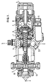
- Fig. 1 is a longitudinal cross-section of an automatic spraygun according to the present invention;
- Fig. 2 is a fragmentary axial cross-section of an air cap and indexing assembly on an enlarged scale;
- Fig. 3 is a front elevation of the seal;
- Fig. 4 is an axial section of the seal taken along the line 4-4 in Fig. 3; and
- Fig. 5 is a section taken along the line 5-5 of Fig. 1 with the addition of the mounting stud and mounting fixture.
- The spraygun illustrated in Fig. 1 comprises a body 1 within which are mounted conventional mechanisms as described in our co-pending application No. 8914130.3 to control the flow of air to a
nozzle 2. The fluid to be sprayed via the nozzle is metered by aneedle 3 the fine adjustment of which is controlled by the control knob 4. Air is supplied to the gun via theinlet 5 passing along a series of passages within the gun body to an air cap (shown in Fig 2). The control mechanism operating theneedle 3 is sealed from the air flow path by "Shamban" double delta seals 6 and is urged to the forward position by stainless steelhelical springs 7 and 8. - The air cap indexing assembly according to the present invention is shown on an enlarged scale in Figs. 2 to 4 and comprises an air cap 8 (see Fig. 2) mounted to rotate on the spraygun body 1 having a
recess 9. - A
baffle 10 made of metal axially aligned and non-rotatable on the body 1 with the interposition of aseal 11 mounted on thebaffle 10 and seated in arecess 12 in the rear face of the baffle and in therecess 9 of the body. The seal is shown in detail in Figs. 3 and 4 and comprises acentral aperture 13 and inner andouter beads beads holes 16 which are so spaced from one another to allow air to transfer evenly fromannular chamber 1a in the sprayhead toannular chamber 10a in thebaffle 10. - A
pin 17 is located in one of the aligned holes in the baffle and seal where it locates in ablind hole 18 in the gun body 1. This pin locates the baffles and seal relative to one another and fixes them in the desired arcuate position relative to the gun body. - The air cap 8 is mounted on the
baffle 10 and has horn shapedprojections 19 through which is supplied to shape the fluid to be sprayed. The orientation of the air cap 8 controls the position of the pattern of the spray area of the fluid. The air cap is located to thebaffle 10 by apin 20 and is secured to thebaffle 10 by a screw-threaded collar 21. This location allows the air cap to be indexed at 90° intervals producing a repeatable and a precise targeting of the centre of the spray pattern within 2 mm to 5 mm of the previous setting. - As the automatic sprayguns are operated remotely on robot mechanisms, the spraygun has to be critically adjusted relative to the surface to be sprayed. To facilitate this adjustment, the spraygun body 1 has an aperture 22 (see Figs. 1 and 5) passing transversely of the longitudinal axis of the spraygun about the centre of the spraygun. A
mounting stud 23 is adjustably secured in theaperture 22 and extends from each side of the gun body where it is located in a mounting fixture 24, shown in dotted line in Fig. 5. Themounting stud 23 comprises a central screw-threadedbolt 25 with three spaced collars, acentral collar 26 and twoouter collars - Located on the
bolt 25 are a plurality ofbevelled washers 29 positioned between the central and outer collars, so that by tightening-up anut 30 against the outer collars the bevelled washers are expanded in diameter to adjustably lock themounting stud 23 within theaperture 22. The automatic spraygun can thus be precisely adjusted about the axis of the mounting stud to position the direction of the spray nozzle. The mounting fixture has apin 31 which locates in ahole 32 drilled in the bottom of the spraygun body 1 to precisely locate the lateral position of the spraygun relative to the mounting fixture 24.
Claims (8)
- An automatic spraygun comprising an air cap (8) adjustably secured on the sprayhead of the automatic spraygun, a baffle (10) located on the body (1) of the spraygun and a seal (11) of low density plastics material located between the baffle (10) and the body (1),characterised in that means are provided to locate the air cap (8) in angular increments relative to the spraygun ensuring replacement within accurately predetermined limits.
- A spraygun as claimed in Claim 1, characterised in that the air cap (8) is located in angular increments of 90°.
- A spraygun as claimed in Claim 1 or 2, characterised in that the baffle (10) is made of metal.
- A spraygun as claimed in any preceding claim, characterised in that the seal (11) is made of polyethylene and has a central aperture (13) with inner (14) and outer (15) radial beads on both faces.
- A spraygun as claimed in any preceding claim, characterised in that the air cap (8) is located to the baffle (10) by a pin (17) and is adjustably secured thereto by a screw-threaded collar (21) so that the air cap (8) can be indexed to change the radial position of the spray pattern of the fluid being sprayed.
- A spraygun as claimed in any preceding claim, characterized by a centrally located aperture (22) passing laterally of the longtiudinal axis of the spraygun (1), a mounting stud (23) passing through the aperture and extending from each side of the spraygun to engage apertures in a mounting fixture (24), whereby the mounting stud (23) has at least two collars (26, 27) located on a screw-threaded bolt (25), a plurality of bevelled washers (29) being interposed between the collars (26, 27) such that tightening of the screw-threaded bolt (25) expands the washers (29) radially within the aperture (22) to adjustably secure the mounting stud (23) to the spraygun (1).
- A spraygun as claimed in Claim 6, characterised in that there are three collars (26, 27, 28) on the screw-threaded bolt (25) with two sets of bevelled washers (29) between the two outer collars (27, 28) and a central collar (26).
- A spraygun as claimed in any preceding claim, characterised in that the spraygun (1) is located relative to a mounting fixture (24) by a pin (31) located in a hole (32) in the bottom of the spraygun body (1).
Applications Claiming Priority (3)
| Application Number | Priority Date | Filing Date | Title |
|---|---|---|---|
| GB9002526 | 1990-02-05 | ||
| GB9002526A GB2240492A (en) | 1990-02-05 | 1990-02-05 | Indexing air cap. |
| PCT/GB1991/000167 WO1991011265A2 (en) | 1990-02-05 | 1991-02-05 | Indexing air cap |
Publications (2)
| Publication Number | Publication Date |
|---|---|
| EP0513151A1 EP0513151A1 (en) | 1992-11-19 |
| EP0513151B1 true EP0513151B1 (en) | 1996-07-31 |
Family
ID=10670444
Family Applications (1)
| Application Number | Title | Priority Date | Filing Date |
|---|---|---|---|
| EP91903845A Revoked EP0513151B1 (en) | 1990-02-05 | 1991-02-05 | Automatic spraygun with an indexing air cap |
Country Status (7)
| Country | Link |
|---|---|
| US (1) | US5259558A (en) |
| EP (1) | EP0513151B1 (en) |
| JP (1) | JPH04504681A (en) |
| DE (1) | DE69121193T2 (en) |
| ES (1) | ES2089191T3 (en) |
| GB (1) | GB2240492A (en) |
| WO (1) | WO1991011265A2 (en) |
Families Citing this family (7)
| Publication number | Priority date | Publication date | Assignee | Title |
|---|---|---|---|---|
| US7484676B2 (en) * | 2002-10-24 | 2009-02-03 | 3M Innovative Properties Company | Easy clean spray gun |
| US6971590B2 (en) * | 2003-12-30 | 2005-12-06 | 3M Innovative Properties Company | Liquid spray gun with manually rotatable frictionally retained air cap |
| US7201336B2 (en) * | 2003-12-30 | 2007-04-10 | 3M Innovative Properties Company | Liquid spray gun with non-circular horn air outlet passageways and apertures |
| US7032839B2 (en) * | 2003-12-30 | 2006-04-25 | 3M Innovative Properties Company | Liquid spray gun with manually separable portions |
| US7097118B1 (en) * | 2005-09-15 | 2006-08-29 | Kuan Chang Co., Ltd. | Spray paint gun with shunt control |
| US8382565B2 (en) | 2008-06-09 | 2013-02-26 | International Business Machines Corporation | System and method to redirect and/or reduce airflow using actuators |
| US12208407B2 (en) | 2021-03-05 | 2025-01-28 | Graco Minnesota Inc. | Alignment tool for a spray gun air cap |
Family Cites Families (15)
| Publication number | Priority date | Publication date | Assignee | Title |
|---|---|---|---|---|
| US1717086A (en) * | 1924-10-09 | 1929-06-11 | Binks Mfg Co | Paint spray nozzle |
| US1819116A (en) * | 1925-03-13 | 1931-08-18 | Spraco Inc | Apparatus or tool for applying coating |
| US1586010A (en) * | 1925-10-16 | 1926-05-25 | Shelburne Augustine | Air-brush nozzle |
| US1907031A (en) * | 1928-10-29 | 1933-05-02 | Edith Marie Anderson | Spray gun |
| US1873625A (en) * | 1929-09-16 | 1932-08-23 | Ernest Z Munz | Spraying device |
| US1962911A (en) * | 1932-09-06 | 1934-06-12 | Vilbiss Co | Spray gun |
| US2269057A (en) * | 1938-01-10 | 1942-01-06 | Alexander F Jenkins | Spraying device |
| US2520375A (en) * | 1946-06-24 | 1950-08-29 | Colson Corp | Adapter |
| NL290138A (en) * | 1962-03-14 | |||
| DE1805145A1 (en) * | 1968-10-25 | 1970-09-03 | Gema Ag Appbau | Set up with spray gun |
| US3930656A (en) * | 1974-02-22 | 1976-01-06 | Parker-Hannifin Corporation | Sealed joint and gasket therefor |
| DE2702191C3 (en) * | 1977-01-20 | 1989-03-16 | Bersch & Fratscher GmbH, 8757 Karlstein | Spray device for atomizing liquids |
| US4171096A (en) * | 1977-05-26 | 1979-10-16 | John Welsh | Spray gun nozzle attachment |
| FR2527480A1 (en) * | 1982-05-26 | 1983-12-02 | Hegler Irmgard | MANUAL GUN WITH LOW PRESSURE PAINT FOR INDUSTRIAL USE |
| US4899938A (en) * | 1987-10-28 | 1990-02-13 | Havrilla Jr John W | Liquid spray nozzle adapter |
-
1990
- 1990-02-05 GB GB9002526A patent/GB2240492A/en not_active Withdrawn
-
1991
- 1991-02-05 ES ES91903845T patent/ES2089191T3/en not_active Expired - Lifetime
- 1991-02-05 DE DE69121193T patent/DE69121193T2/en not_active Revoked
- 1991-02-05 WO PCT/GB1991/000167 patent/WO1991011265A2/en not_active Ceased
- 1991-02-05 EP EP91903845A patent/EP0513151B1/en not_active Revoked
- 1991-02-05 US US07/689,895 patent/US5259558A/en not_active Expired - Lifetime
- 1991-02-05 JP JP3504004A patent/JPH04504681A/en active Pending
Also Published As
| Publication number | Publication date |
|---|---|
| GB9002526D0 (en) | 1990-04-04 |
| JPH04504681A (en) | 1992-08-20 |
| ES2089191T3 (en) | 1996-10-01 |
| WO1991011265A3 (en) | 1991-11-14 |
| GB2240492A (en) | 1991-08-07 |
| DE69121193T2 (en) | 1996-11-28 |
| WO1991011265A2 (en) | 1991-08-08 |
| EP0513151A1 (en) | 1992-11-19 |
| DE69121193D1 (en) | 1996-09-05 |
| US5259558A (en) | 1993-11-09 |
Similar Documents
| Publication | Publication Date | Title |
|---|---|---|
| US5036923A (en) | Fire sprinkler with adjustable deflector | |
| EP0327296B1 (en) | Spraygun | |
| US5221170A (en) | Coated threaded fasteners | |
| US5169071A (en) | Nozzle cap for an adhesive dispenser | |
| US5071074A (en) | Angled spray gun | |
| US5765757A (en) | Quick select nozzle system | |
| EP0596939B1 (en) | Improved aircap for paint spray gun | |
| US4613082A (en) | Electrostatic spraying apparatus for robot mounting | |
| CA1147140A (en) | Air-operated spray device | |
| WO1991011265A2 (en) | Indexing air cap | |
| EP0112181B1 (en) | Reversible spray tip | |
| EP0474155A2 (en) | Nozzle cap for an adhesive dispenser | |
| EP4052797B1 (en) | Alignment tool for a spray gun air cap | |
| US4850538A (en) | Adjustable nozzle | |
| KR20180006865A (en) | Skirt for a rotary projector of coating product comprising at least three distinct series of air ejecting nozzles | |
| EP2760591B1 (en) | Spray device having curved passages | |
| US4666086A (en) | Remotely controlled spray gun | |
| CA1038622A (en) | Spray gun | |
| US4991966A (en) | Optical positioning method and system | |
| US5487781A (en) | Mastic applicator system | |
| EP2007524B1 (en) | Spray device | |
| SU973176A1 (en) | Jet nozzle | |
| SU1313450A1 (en) | Fire-hose barrel | |
| EP1270964B1 (en) | Fastening assembly for the adjustable mounting of an apparatus | |
| GB2240491A (en) | A sprayhead assembly for sprayguns |
Legal Events
| Date | Code | Title | Description |
|---|---|---|---|
| PUAI | Public reference made under article 153(3) epc to a published international application that has entered the european phase |
Free format text: ORIGINAL CODE: 0009012 |
|
| 17P | Request for examination filed |
Effective date: 19920812 |
|
| AK | Designated contracting states |
Kind code of ref document: A1 Designated state(s): BE DE ES FR GB IT SE |
|
| 17Q | First examination report despatched |
Effective date: 19940124 |
|
| GRAH | Despatch of communication of intention to grant a patent |
Free format text: ORIGINAL CODE: EPIDOS IGRA |
|
| GRAH | Despatch of communication of intention to grant a patent |
Free format text: ORIGINAL CODE: EPIDOS IGRA |
|
| GRAA | (expected) grant |
Free format text: ORIGINAL CODE: 0009210 |
|
| AK | Designated contracting states |
Kind code of ref document: B1 Designated state(s): BE DE ES FR GB IT SE |
|
| REF | Corresponds to: |
Ref document number: 69121193 Country of ref document: DE Date of ref document: 19960905 |
|
| ET | Fr: translation filed | ||
| REG | Reference to a national code |
Ref country code: ES Ref legal event code: FG2A Ref document number: 2089191 Country of ref document: ES Kind code of ref document: T3 |
|
| ITF | It: translation for a ep patent filed | ||
| REG | Reference to a national code |
Ref country code: ES Ref legal event code: FG2A Ref document number: 2089191 Country of ref document: ES Kind code of ref document: T3 |
|
| PGFP | Annual fee paid to national office [announced via postgrant information from national office to epo] |
Ref country code: FR Payment date: 19970115 Year of fee payment: 7 |
|
| PGFP | Annual fee paid to national office [announced via postgrant information from national office to epo] |
Ref country code: SE Payment date: 19970116 Year of fee payment: 7 |
|
| PGFP | Annual fee paid to national office [announced via postgrant information from national office to epo] |
Ref country code: BE Payment date: 19970128 Year of fee payment: 7 |
|
| PLBI | Opposition filed |
Free format text: ORIGINAL CODE: 0009260 |
|
| PLBQ | Unpublished change to opponent data |
Free format text: ORIGINAL CODE: EPIDOS OPPO |
|
| PLBF | Reply of patent proprietor to notice(s) of opposition |
Free format text: ORIGINAL CODE: EPIDOS OBSO |
|
| 26 | Opposition filed |
Opponent name: DUERR SYSTEMS GMBH Effective date: 19970429 |
|
| PLBF | Reply of patent proprietor to notice(s) of opposition |
Free format text: ORIGINAL CODE: EPIDOS OBSO |
|
| PLBF | Reply of patent proprietor to notice(s) of opposition |
Free format text: ORIGINAL CODE: EPIDOS OBSO |
|
| RAP2 | Party data changed (patent owner data changed or rights of a patent transferred) |
Owner name: ITW LIMITED |
|
| PGFP | Annual fee paid to national office [announced via postgrant information from national office to epo] |
Ref country code: DE Payment date: 19980123 Year of fee payment: 8 |
|
| PGFP | Annual fee paid to national office [announced via postgrant information from national office to epo] |
Ref country code: GB Payment date: 19980127 Year of fee payment: 8 |
|
| PG25 | Lapsed in a contracting state [announced via postgrant information from national office to epo] |
Ref country code: SE Free format text: LAPSE BECAUSE OF NON-PAYMENT OF DUE FEES Effective date: 19980206 |
|
| PGFP | Annual fee paid to national office [announced via postgrant information from national office to epo] |
Ref country code: ES Payment date: 19980209 Year of fee payment: 8 |
|
| PG25 | Lapsed in a contracting state [announced via postgrant information from national office to epo] |
Ref country code: BE Free format text: LAPSE BECAUSE OF NON-PAYMENT OF DUE FEES Effective date: 19980228 |
|
| RDAH | Patent revoked |
Free format text: ORIGINAL CODE: EPIDOS REVO |
|
| BERE | Be: lapsed |
Owner name: ITW LTD Effective date: 19980228 |
|
| EUG | Se: european patent has lapsed |
Ref document number: 91903845.5 |
|
| RDAG | Patent revoked |
Free format text: ORIGINAL CODE: 0009271 |
|
| STAA | Information on the status of an ep patent application or granted ep patent |
Free format text: STATUS: PATENT REVOKED |
|
| REG | Reference to a national code |
Ref country code: FR Ref legal event code: ST |
|
| 27W | Patent revoked |
Effective date: 19980827 |
|
| GBPR | Gb: patent revoked under art. 102 of the ep convention designating the uk as contracting state |
Free format text: 980827 |