EP0512666B1 - Improved knee brace - Google Patents
Improved knee brace Download PDFInfo
- Publication number
- EP0512666B1 EP0512666B1 EP92301166A EP92301166A EP0512666B1 EP 0512666 B1 EP0512666 B1 EP 0512666B1 EP 92301166 A EP92301166 A EP 92301166A EP 92301166 A EP92301166 A EP 92301166A EP 0512666 B1 EP0512666 B1 EP 0512666B1
- Authority
- EP
- European Patent Office
- Prior art keywords
- knee
- knee brace
- frame member
- user
- members
- Prior art date
- Legal status (The legal status is an assumption and is not a legal conclusion. Google has not performed a legal analysis and makes no representation as to the accuracy of the status listed.)
- Expired - Lifetime
Links
Images

Classifications
-
- A—HUMAN NECESSITIES
- A61—MEDICAL OR VETERINARY SCIENCE; HYGIENE
- A61F—FILTERS IMPLANTABLE INTO BLOOD VESSELS; PROSTHESES; DEVICES PROVIDING PATENCY TO, OR PREVENTING COLLAPSING OF, TUBULAR STRUCTURES OF THE BODY, e.g. STENTS; ORTHOPAEDIC, NURSING OR CONTRACEPTIVE DEVICES; FOMENTATION; TREATMENT OR PROTECTION OF EYES OR EARS; BANDAGES, DRESSINGS OR ABSORBENT PADS; FIRST-AID KITS
- A61F5/00—Orthopaedic methods or devices for non-surgical treatment of bones or joints; Nursing devices ; Anti-rape devices
- A61F5/01—Orthopaedic devices, e.g. long-term immobilising or pressure directing devices for treating broken or deformed bones such as splints, casts or braces
- A61F5/0102—Orthopaedic devices, e.g. long-term immobilising or pressure directing devices for treating broken or deformed bones such as splints, casts or braces specially adapted for correcting deformities of the limbs or for supporting them; Ortheses, e.g. with articulations
- A61F5/0123—Orthopaedic devices, e.g. long-term immobilising or pressure directing devices for treating broken or deformed bones such as splints, casts or braces specially adapted for correcting deformities of the limbs or for supporting them; Ortheses, e.g. with articulations for the knees
-
- A—HUMAN NECESSITIES
- A61—MEDICAL OR VETERINARY SCIENCE; HYGIENE
- A61F—FILTERS IMPLANTABLE INTO BLOOD VESSELS; PROSTHESES; DEVICES PROVIDING PATENCY TO, OR PREVENTING COLLAPSING OF, TUBULAR STRUCTURES OF THE BODY, e.g. STENTS; ORTHOPAEDIC, NURSING OR CONTRACEPTIVE DEVICES; FOMENTATION; TREATMENT OR PROTECTION OF EYES OR EARS; BANDAGES, DRESSINGS OR ABSORBENT PADS; FIRST-AID KITS
- A61F5/00—Orthopaedic methods or devices for non-surgical treatment of bones or joints; Nursing devices ; Anti-rape devices
- A61F5/01—Orthopaedic devices, e.g. long-term immobilising or pressure directing devices for treating broken or deformed bones such as splints, casts or braces
- A61F5/0102—Orthopaedic devices, e.g. long-term immobilising or pressure directing devices for treating broken or deformed bones such as splints, casts or braces specially adapted for correcting deformities of the limbs or for supporting them; Ortheses, e.g. with articulations
- A61F2005/0132—Additional features of the articulation
- A61F2005/0137—Additional features of the articulation with two parallel pivots
-
- A—HUMAN NECESSITIES
- A61—MEDICAL OR VETERINARY SCIENCE; HYGIENE
- A61F—FILTERS IMPLANTABLE INTO BLOOD VESSELS; PROSTHESES; DEVICES PROVIDING PATENCY TO, OR PREVENTING COLLAPSING OF, TUBULAR STRUCTURES OF THE BODY, e.g. STENTS; ORTHOPAEDIC, NURSING OR CONTRACEPTIVE DEVICES; FOMENTATION; TREATMENT OR PROTECTION OF EYES OR EARS; BANDAGES, DRESSINGS OR ABSORBENT PADS; FIRST-AID KITS
- A61F5/00—Orthopaedic methods or devices for non-surgical treatment of bones or joints; Nursing devices ; Anti-rape devices
- A61F5/01—Orthopaedic devices, e.g. long-term immobilising or pressure directing devices for treating broken or deformed bones such as splints, casts or braces
- A61F5/0102—Orthopaedic devices, e.g. long-term immobilising or pressure directing devices for treating broken or deformed bones such as splints, casts or braces specially adapted for correcting deformities of the limbs or for supporting them; Ortheses, e.g. with articulations
- A61F2005/0132—Additional features of the articulation
- A61F2005/0165—Additional features of the articulation with limits of movement
-
- A—HUMAN NECESSITIES
- A61—MEDICAL OR VETERINARY SCIENCE; HYGIENE
- A61F—FILTERS IMPLANTABLE INTO BLOOD VESSELS; PROSTHESES; DEVICES PROVIDING PATENCY TO, OR PREVENTING COLLAPSING OF, TUBULAR STRUCTURES OF THE BODY, e.g. STENTS; ORTHOPAEDIC, NURSING OR CONTRACEPTIVE DEVICES; FOMENTATION; TREATMENT OR PROTECTION OF EYES OR EARS; BANDAGES, DRESSINGS OR ABSORBENT PADS; FIRST-AID KITS
- A61F5/00—Orthopaedic methods or devices for non-surgical treatment of bones or joints; Nursing devices ; Anti-rape devices
- A61F5/01—Orthopaedic devices, e.g. long-term immobilising or pressure directing devices for treating broken or deformed bones such as splints, casts or braces
- A61F5/0102—Orthopaedic devices, e.g. long-term immobilising or pressure directing devices for treating broken or deformed bones such as splints, casts or braces specially adapted for correcting deformities of the limbs or for supporting them; Ortheses, e.g. with articulations
- A61F2005/0132—Additional features of the articulation
- A61F2005/0172—Additional features of the articulation with cushions
Definitions
- the present invention relates to braces for supporting joints, and more particularly to a knee brace specifically adapted for use in athletic, i.e. sports, applications as specified in the preamble of Claim 1.
- a knee brace is known e.g. from EP-A-0 382 976.
- the knee joint although frequently considered a hinge joint, actually comprises two joints, lateral and medial, between the femur and tibia, and one arthrodial joint between the patella and femur.
- the primary movements of the knee comprise flexion, i.e., rearward rotational movement of the tibia relative the femur, and extension, i.e. forward rotational movement of the tibia relative the femur.
- the flexion and extension movements of the knee joint are not simply pivotal movements about a fixed axis.
- the axis around which movement takes place shifts backward, and during extension it shifts forward. This is different from a more typical hinge joint, such as an elbow, where the axis of rotation does not shift.
- the tibia is rotated inward or rearward and the joint in effect is disposed in a "locked" position with the ligaments taut. This gives the joint greater stability in the extended position.
- the tibia initially lowers or moves downwardly with the small external rotation of the tibia which "unlocks" the joint and subsequently the tibia rotates or rolls about the joint to full flexion. Accordingly, the initial unlocking of the knee joint during flexion precedes actual full rotation of the knee.
- a knee brace Due to the above complexity of knee movement, for a knee brace to more fully support the knee joint of the user and facilitate rehabilitation and/or prevent re-injury of an injured knee joint, the brace must more closely analogize the movement of the knee than a simple hinge mechanism. Additionally, with specific relation to athletic or sports applications, the requirement for such analogized movement becomes acute. Further, for such sports applications, a knee brace must be relatively lightweight to avoid over-constriction which reduces success in the athletic endeavor, yet possess sufficient structural strength to adequately support the knee joint during impact thereupon.
- knee braces In recognizing the need for an effective sports knee brace, various knee braces have been introduced into the marketplace. Such contemporary knee braces, however, have generally failed to provide the precise simulation of knee joint movement as described above or have comprised relatively heavy, bulky apparatus, thereby detracting from the user's athletic endeavor. Further, such contemporary designs have typically failed to possess sufficient structural integrity to prevent re-injury of the knee joint as may be occasioned by impact to the knee joint during physical sport endeavors.
- most contemporary sports braces have further been deficient in that the brace is not constructed in a manner so as to provide a consistently firm interface between the knee brace and the portion of the knee joint adjacent the crest of the tibia. This particular area of the knee joint typically becomes swollen after surgery or the occurrence of other trauma to the knee. As such, when the user is initially fitted with a knee brace, the knee brace is typically sized to conform to the shape of the knee at the time of the fitting. Thus, as the swelling of the knee subsides, oftentimes a gap is formed between the brace and the knee thereby necessitating that remedial measures be taken on the knee brace to alleviate the gap and achieve a more precise fit of the brace to the knee. Finally, most contemporary sports braces have further been deficient in their lack of providing suitable protection to the patella portion of the knee joint.
- EP-A-0382976 proposes a knee brace of the kind comprising an upper frame member positionable above the knee joint of a user and a lower frame member positionable below the knee joint of the user, each of said frame members being configured to provide a body portion disposed adjacent the front of the user's leg when the knee brace is attached thereto and side portions extending laterally on opposite sides of the knee joint when the knee brace is attached to the user's leg, a pair of hinge members disposed substantially adjacent the knee joint when the knee brace is attached to the user's leg and connected to corresponding side portions of said frame members to pivot said frame members about the knee joint, and a tibia pad attached to the inner surface of the body portion of said lower frame member to provide a firm interface between said lower frame member and the portion of the knee joint adjacent the crest of the tibia; a similar knee brace is described in International Patent Specification W089/04155.
- a knee brace of the kind referred to above is characterised by said tibia pad comprising a central part which is attached to a central portion of said inner surface of the body portion of said lower frame member and laterally extending portions which are not secured to said inner surface of the body portion of said lower frame member such that they can be pulled away from said inner surface, and by removable means being provided which are interposed between the laterally extending portions of the tibia pad and said inner surface of the body portion of said lower frame member for adjusting the position of said tibia pad relative to the portion of the knee joint adjacent the crest of the tibia.
- the positioning of the tibia pad relative to the knee joint can be readily adjusted so that the tibia pad is always firmly interfaced thereto, irrespective of the degree of knee swelling, without the necessity of performing time-consuming and costly remedial operations to the structure of the brace.
- said removable means for adjusting the tibia pad comprises at least one wedge pad, which conveniently is held in position by hook and loop patches.
- the present invention additionally incorporates a patella cup which is removably attachable to the upper portion of the tibia pad.
- the patella cup is oriented within the knee brace in a manner so as to cover the knee cap of the knee joint, thereby protecting it during sports endeavors.
- the brace of the present invention incorporates a unique stop mechanism into the ratio-swing hinges of the frame members.
- the stop mechanism comprises differing sized stop members which may be rapidly inserted into the hinges to restrict extension without restricting flexion of the knee joint.
- the stop members are formed as progressively sized elements which serve to limit extension in varying degree segments, such as five degrees, ten degrees, fifteen degrees, and twenty degrees.
- differing stop members may be progressively utilized to allow greater extension as desired.
- condylar pads may be connected to the hinge members for providing a cushion between the lateral and medial aspects of the knee joint and the hinge members.
- strap members are provided which are attached directly to the upper and lower frame members.
- the knee brace 10 of the present invention specifically adapted for athletic, i.e. sports, applications, is depicted.
- the knee brace 10 is illustrated in a left-leg embodiment which is adapted to be worn upon the left leg of a user.
- the invention is additionally applicable to right-leg embodiments with the structure of the brace 10 being the same but reversed in orientation.
- the knee brace 10 is composed of an upper frame member 12 and a lower frame member 14.
- Upper frame member 12 and lower frame member 14 each have a generally Y-shaped configuration and are disposed in an inverted relative orientation and positionable on opposite sides of the knee joint of a user.
- upper frame member 12 and lower frame member 14 are formed from a fiber reinforced composite material having sufficient rigidity to withstand impact forces encountered during physical sport endeavors yet be sufficiently light in weight so as not to impair the physical sport activity.
- a fiber reinforced composite material having sufficient rigidity to withstand impact forces encountered during physical sport endeavors yet be sufficiently light in weight so as not to impair the physical sport activity.
- other materials possessing sufficient strength and rigidity are contemplated herein.
- upper frame member 12 and the lower frame member 14 are pivotally connected to one another by a pair of ratio-swing hinges 16, each composed generally of an upper hinge component 18 and a lower hinge component 20 which are interconnected by an exterior plate member 22.
- upper hinge component 18 includes an upper insert portion 24 formed thereon and a first aperture 26 disposed therein.
- lower hinge component 20 includes a lower insert portion 28 formed thereon and a second aperture 30 disposed therein.
- the fiber-reinforced composite materials comprising upper frame member 12 are laminated directly to and about the upper insert portion 24 of upper hinge component 18.
- upper insert portion 24 is received within and integrally connected to upper frame member 12.
- FIGS. 9 and 10 This method of interconnection is particularly illustrated in FIGS. 9 and 10.
- the lower insert portion 28 of lower hinge component 20 is received within and integrally connected to the lower frame member 14 in the same manner as previously described with respect to upper hinge component 18.
- this manner of interfacing upper hinge component 18 and lower hinge component 20 to upper frame member 12 and lower frame member 14, respectively provides knee brace 10 with substantially increased structural rigidity.
- Disposed within the plate member 22 is a third aperture 32 and a fourth aperture 34.
- Elate member 22 is pivotally mounted to upper hinge component 18 and lower hinge component 20 and hence upper frame member 12 and lower frame member 14 via pivot pins 36 and 38, respectively.
- pivot pin 36 is received into the coaxially aligned apertures 26 and 32 and pivot pin 38 is received into the coaxially aligned apertures 30 and 34. Due to the positioning of the pivot pins 36 and 38 upon the plate member 22 and frame members 12 and 14, the hinges 16 provide a ratio-swing movement between the frame members 12 and 14 as the frame members 12 and 14 are articulated relative one another.
- condylar pads 40 are attached to upper hinge component 18 and lower hinge component 20 to provide a cushion between the lateral and medial aspects of the knee joint and the hinges 16. Additionally, the ratio-swing hinges 16 are specifically designed to mount a stop member insert 42 between the upper hinge component 18 and the lower hinge component 20.
- the stop member insert 42 comprises an elongate member which is retained between exterior plate member 22 and a condylar pad 40 by way of a threaded aperture 44 disposed therein which is adapted to receive a screw extending through a condylar pad 40.
- the effective width of the stop member 42 is sized as desired to form a physical stop or barrier which prohibits relative movement between the upper frame member 12 and the lower frame member 14 in extension movement of the knee yet insures free movement between the frame members 12 and 14 in flexion.
- the effective width of the stop member insert 42 may be varied by supplying differing-sized stop member inserts 42 with the brace 10, with the differing-sized stop member inserts 42 being sized to progressively limit the degree of extension of the knee, i.e. five-degree extension, ten-degree extension, fifteen-degree extension, etc.
- stop member 42 is removed simply by removing the screw from condylar pad 40.
- the present invention accommodates rehabilitation and prevents hyperextension of the knee by allowing a user to progressively increase the extension allowed by the knee brace 10 merely by inserting differing-sized stop member inserts 42 within the ratio-swing hinges 16.
- ratio-swing hinges 16 allows relative movement of the upper frame member 12 and lower frame member 14 in a regulated manner varying pivot axis which simulates normal knee movement wherein during initial movement of the tibia relative the femur in flexion, the tibia slightly lowers to "unlock” the knee joint and once "unlocked” subsequently pivots rapidly backward in flexion.
- the upper hinge component 18, lower hinge component 20, and stop members 42 are formed of plastic, though it will be appreciated that other materials may be utilized.
- the plate member 22 is preferably formed of stainless steel.
- Tibia pad 46 Attached to the inner surface 14a of lower frame member 14 is a tibia pad 46.
- Tibia pad 46 which is preferably constructed from foam rubber material, has a generally T-shaped configuration. Tibia pad 46 is used to provide a firm interface between the lower frame member 14 and the portion of the knee joint adjacent the crest of the tibia. As previously discussed, oftentimes the knee of the user is affected with post-surgical or post-trauma swelling when the knee brace 10 is fitted thereto. During the initial fitting of the knee brace 10 to the user, tibia pad 46 is firmly abutted against the swollen knee.
- a gap between tibia pad 46 and the portion of the knee joint adjacent the crest of the tibia will eventually be formed.
- the formation of such a gap diminishes the snug fit of the knee brace 10 against the leg of a user, thereby decreasing the effectiveness of the knee brace 10.
- means are provided to adjust the position of the tibia pad 46 relative to the portion of the knee joint adjacent the crest of the tibia so as to provide a consistently firm interface between the lower frame member 14 and knee joint.
- lateral portions 48, 50 of tibia pad 46 are not secured to inner surface 14a.
- lateral portions 48, 50 may be pulled away from inner surface 14a.
- the outer surfaces of lateral portions 48, 50 which normally come in contact with inner surface 14a, are covered with hook and loop "Velcro" (Registered Trade Mark) patches 52.
- Velcro Registered Trade Mark
- one or more wedge members 54 may be inserted between lateral portion 48 and/or lateral portion 50 and inner surface 14a. As seen in FIG.
- each of wedge members 54 includes a "Velcro"patch 56 thereon.
- wedge members 54 are maintained in position between lateral portion 48 and/or lateral portion 50 and inner surface 14a through the interconnection of "Velcro"patches 56 to"Velcro”patches 52.
- the further wedge members 54 are inserted toward the vertical portion of tibia pad 46, the greater the degree of separation between lateral portions 48, 50 and inner surface 14a.
- the tibia pad 46 may be incrementally adjusted as desired so as to stay in firm, abutting contact with the portion of the knee joint adjacent the crest of the tibia.
- the wedge members 54 may be inserted between one or both of the lateral portions 48, 50 so as to retain contact of the tibia pad 46 against the knee.
- Wedge members 54 are preferably constructed from foam rubber though other materials may be utilized.
- upper frame member 12 is formed to include a first laterally extending portion 58 which is adapted to conform to the lateral aspect of the lower portion of the user's thigh when knee brace 10 is placed upon the leg of the user.
- first laterally extending portion 58 Disposed on the inner surface of first laterally extending portion 58 is a first foam rubber pad 60.
- lower frame member 14 is formed to include a second laterally extending portion 62 which is adapted to conform to the lateral aspect of the upper portion of the user's calf when knee brace 10 is attached to the leg of the user.
- second laterally extending portion 62 includes a second foam rubber pad 64 attached to the inner surface thereof.
- the knee brace 10 of the present invention is preferably attached to the user's leg via strap members 66, 68, 70, and 72.
- strap members 66, 68 are attached directly to upper frame member 12 and are adapted to extend about the soft tissue of the user adjacent the femur.
- Strap members 70 and 72 are preferably attached directly to lower frame member 14 and adapted to extend about the soft tissue of the user adjacent the tibia.
- an adjustment member and clasp may be provided on such strap members.
- Patella cup 74 is removably attachable to tibia pad 46 and used to cover the knee cap portion of the knee joint when knee brace 10 is attached to the leg of the user.
- a cup pad 76 Secured to the inner surface of patella cup 74 is a cup pad 76 preferably constructed from foam rubber.
- the attachment of patella cup 74 to tibia pad 46 is preferably facilitated by snaps 78 positioned on the outer surface of patella cup 74. Snaps 78 are adapted to be interfaced to snaps 80 connected to tibia pad 46 adjacent the upper edge thereof.
- patella cup 74 is an optional component of knee brace 10 and need not necessarily be included therewith.
- Patella cup 74 further includes a cup strap 82 attached to the outer surface thereof. Though not shown, in those instances when a patella cup 74 is included with the knee brace 10, cup strap 82 is secured to strap member 68 to aid in maintaining the patella cup 74 over the knee cap of a user.
- the knee brace 10 of the present invention may be described.
- the knee brace 10 is positioned about the user's leg.
- Initial sizing of the knee brace 10 for the user is facilitated by insuring that the distance between the ratio-swing hinge members 16 is slightly greater than the medial lateral width of the knee joint such that the hinges 16 are disposed on opposite sides of the knee joint in close proximity thereto.
- Such sizing of the knee brace 10 is preferably facilitated by the specification formation of the upper frame member 12 and lower frame member 14 to conform to the leg of a particular user.
- the strap members 66 and 68 are firmly affixed about the soft tissue of the user adjacent the femur. Subsequently, the strap members 70 and 72 are tightened in an analogous manner whereby they are securely fastened about the sort tissue of the user's leg adjacent the tibia. Additionally, if a patella cup 74 is provided within the knee brace 10, the cup strap 82 is then secured to the strap member 68.
- the position of the tibia pad 46 is then adjusted relative to lower frame member 14 so as to be in firm contact with the portion of the knee joint adjacent the crest of the tibia. As such, this particular operation insures a snug fit between the lower frame member 14 and leg of the user.
- the distance into which the wedge members 54 are inserted between the tibia pad 46 and lower frame member 14 depends upon the desired degree of separation between the tibia pad 46 and lower frame member 14.
Landscapes
- Health & Medical Sciences (AREA)
- Nursing (AREA)
- Orthopedic Medicine & Surgery (AREA)
- Engineering & Computer Science (AREA)
- Biomedical Technology (AREA)
- Heart & Thoracic Surgery (AREA)
- Vascular Medicine (AREA)
- Life Sciences & Earth Sciences (AREA)
- Animal Behavior & Ethology (AREA)
- General Health & Medical Sciences (AREA)
- Public Health (AREA)
- Veterinary Medicine (AREA)
- Orthopedics, Nursing, And Contraception (AREA)
- Transition And Organic Metals Composition Catalysts For Addition Polymerization (AREA)
- Pharmaceuticals Containing Other Organic And Inorganic Compounds (AREA)
- Prostheses (AREA)
Abstract
Description
- The present invention relates to braces for supporting joints, and more particularly to a knee brace specifically adapted for use in athletic, i.e. sports, applications as specified in the preamble of Claim 1. Such a knee brace is known e.g. from EP-A-0 382 976.
- As is well known, the knee joint, although frequently considered a hinge joint, actually comprises two joints, lateral and medial, between the femur and tibia, and one arthrodial joint between the patella and femur. The primary movements of the knee comprise flexion, i.e., rearward rotational movement of the tibia relative the femur, and extension, i.e. forward rotational movement of the tibia relative the femur.
- The flexion and extension movements of the knee joint are not simply pivotal movements about a fixed axis. During flexion, the axis around which movement takes place shifts backward, and during extension it shifts forward. This is different from a more typical hinge joint, such as an elbow, where the axis of rotation does not shift. As full extension is reached, the tibia is rotated inward or rearward and the joint in effect is disposed in a "locked" position with the ligaments taut. This gives the joint greater stability in the extended position. As flexion is initiated, the tibia initially lowers or moves downwardly with the small external rotation of the tibia which "unlocks" the joint and subsequently the tibia rotates or rolls about the joint to full flexion. Accordingly, the initial unlocking of the knee joint during flexion precedes actual full rotation of the knee.
- Due to the above complexity of knee movement, for a knee brace to more fully support the knee joint of the user and facilitate rehabilitation and/or prevent re-injury of an injured knee joint, the brace must more closely analogize the movement of the knee than a simple hinge mechanism. Additionally, with specific relation to athletic or sports applications, the requirement for such analogized movement becomes acute. Further, for such sports applications, a knee brace must be relatively lightweight to avoid over-constriction which reduces success in the athletic endeavor, yet possess sufficient structural strength to adequately support the knee joint during impact thereupon.
- In recognizing the need for an effective sports knee brace, various knee braces have been introduced into the marketplace. Such contemporary knee braces, however, have generally failed to provide the precise simulation of knee joint movement as described above or have comprised relatively heavy, bulky apparatus, thereby detracting from the user's athletic endeavor. Further, such contemporary designs have typically failed to possess sufficient structural integrity to prevent re-injury of the knee joint as may be occasioned by impact to the knee joint during physical sport endeavors.
- Additionally, most contemporary sports braces have further been deficient in that the brace is not constructed in a manner so as to provide a consistently firm interface between the knee brace and the portion of the knee joint adjacent the crest of the tibia. This particular area of the knee joint typically becomes swollen after surgery or the occurrence of other trauma to the knee. As such, when the user is initially fitted with a knee brace, the knee brace is typically sized to conform to the shape of the knee at the time of the fitting. Thus, as the swelling of the knee subsides, oftentimes a gap is formed between the brace and the knee thereby necessitating that remedial measures be taken on the knee brace to alleviate the gap and achieve a more precise fit of the brace to the knee. Finally, most contemporary sports braces have further been deficient in their lack of providing suitable protection to the patella portion of the knee joint.
- Applicants Patent Specification EP-A-0382976 proposes a knee brace of the kind comprising an upper frame member positionable above the knee joint of a user and a lower frame member positionable below the knee joint of the user, each of said frame members being configured to provide a body portion disposed adjacent the front of the user's leg when the knee brace is attached thereto and side portions extending laterally on opposite sides of the knee joint when the knee brace is attached to the user's leg, a pair of hinge members disposed substantially adjacent the knee joint when the knee brace is attached to the user's leg and connected to corresponding side portions of said frame members to pivot said frame members about the knee joint, and a tibia pad attached to the inner surface of the body portion of said lower frame member to provide a firm interface between said lower frame member and the portion of the knee joint adjacent the crest of the tibia; a similar knee brace is described in International Patent Specification W089/04155. Although these arrangements alleviate the above-referenced deficiencies, problems may still arise in adjusting the tibia pad to provide a firm application.
- According to the present invention a knee brace of the kind referred to above is characterised by said tibia pad comprising a central part which is attached to a central portion of said inner surface of the body portion of said lower frame member and laterally extending portions which are not secured to said inner surface of the body portion of said lower frame member such that they can be pulled away from said inner surface, and by removable means being provided which are interposed between the laterally extending portions of the tibia pad and said inner surface of the body portion of said lower frame member for adjusting the position of said tibia pad relative to the portion of the knee joint adjacent the crest of the tibia.
- Thus, in accordance with the invention, the positioning of the tibia pad relative to the knee joint can be readily adjusted so that the tibia pad is always firmly interfaced thereto, irrespective of the degree of knee swelling, without the necessity of performing time-consuming and costly remedial operations to the structure of the brace.
- Preferably, said removable means for adjusting the tibia pad comprises at least one wedge pad, which conveniently is held in position by hook and loop patches.
- The present invention additionally incorporates a patella cup which is removably attachable to the upper portion of the tibia pad. The patella cup is oriented within the knee brace in a manner so as to cover the knee cap of the knee joint, thereby protecting it during sports endeavors.
- So as not to hamper the physical endeavor yet prevent any hyper-extension of the knee joint during use, the brace of the present invention incorporates a unique stop mechanism into the ratio-swing hinges of the frame members. In a preferred embodiment, the stop mechanism comprises differing sized stop members which may be rapidly inserted into the hinges to restrict extension without restricting flexion of the knee joint. Preferably, the stop members are formed as progressively sized elements which serve to limit extension in varying degree segments, such as five degrees, ten degrees, fifteen degrees, and twenty degrees.
- During rehabilitation of the knee, differing stop members may be progressively utilized to allow greater extension as desired.
- Conveniently, condylar pads may be connected to the hinge members for providing a cushion between the lateral and medial aspects of the knee joint and the hinge members.
- To maintain the knee brace upon the leg of the user, strap members are provided which are attached directly to the upper and lower frame members.
- These as well as other features of the present invention will become more apparent upon reference to the drawings wherein:
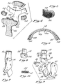
- FIG. 1 is a front perspective view of the knee brace of the present invention;
- FIG. 2 is a rear perspective view of the knee brace of the present invention;
- FIG. 3 is a front perspective view of the tibia pad and patella cup of the present invention, illustrating the manner in which they are interfaced to each other;
- FIG. 4 is an exploded view illustrating the components used to adjust the position of the tibia pad relative to the knee joint;
- FIG. 5 is a perspective view of a wedge pad illustrated in FIG. 4;
- FIG. 6 is a cross-sectional view taken along line 6-6 of FIG. 2;
- FIG. 7 is partial perspective view of a ratio-swing hinge as interfaced to the frame members;
- FIG. 8 is a perspective view of the upper hinge component of a ratio-swing hinge;
- FIG. 9 is an exploded view illustrating the components comprising a ratio-swing hinge and further depicting the manner in which the upper and lower hinge components are received into the upper and lower frame members; and
- FIG. 10 is a cross-sectional view taken along line 10-10 of FIG. 9.
- The description set forth below in connection with the appended drawings is intended merely as a description of the presently preferred embodiment of the invention, and is not intended to represent the only form in which the present invention may be utilized. Thus, the description sets forth, by way of example, the functions and structural elements of the preferred embodiment within the scope of the Claims.
- Referring to the drawings, the
knee brace 10 of the present invention, specifically adapted for athletic, i.e. sports, applications, is depicted. For purposes of illustration, theknee brace 10 is illustrated in a left-leg embodiment which is adapted to be worn upon the left leg of a user. However, it will be recognized that the invention is additionally applicable to right-leg embodiments with the structure of thebrace 10 being the same but reversed in orientation. As best shown in FIGS. 1 and 2, theknee brace 10 is composed of anupper frame member 12 and alower frame member 14.Upper frame member 12 andlower frame member 14 each have a generally Y-shaped configuration and are disposed in an inverted relative orientation and positionable on opposite sides of the knee joint of a user. In the preferred embodiment,upper frame member 12 andlower frame member 14 are formed from a fiber reinforced composite material having sufficient rigidity to withstand impact forces encountered during physical sport endeavors yet be sufficiently light in weight so as not to impair the physical sport activity. However, other materials possessing sufficient strength and rigidity are contemplated herein. - The
upper frame member 12 and thelower frame member 14 are pivotally connected to one another by a pair of ratio-swing hinges 16, each composed generally of an upper hinge component 18 and a lower hinge component 20 which are interconnected by anexterior plate member 22. Referring now to FIGS. 7-10, upper hinge component 18 includes anupper insert portion 24 formed thereon and afirst aperture 26 disposed therein. Similarly, lower hinge component 20 includes alower insert portion 28 formed thereon and asecond aperture 30 disposed therein. In the preferred embodiment, during the construction ofupper frame member 12, the fiber-reinforced composite materials comprisingupper frame member 12 are laminated directly to and about theupper insert portion 24 of upper hinge component 18. Thus,upper insert portion 24 is received within and integrally connected toupper frame member 12. This method of interconnection is particularly illustrated in FIGS. 9 and 10. Likewise, thelower insert portion 28 of lower hinge component 20 is received within and integrally connected to thelower frame member 14 in the same manner as previously described with respect to upper hinge component 18. As can be appreciated, this manner of interfacing upper hinge component 18 and lower hinge component 20 toupper frame member 12 andlower frame member 14, respectively, providesknee brace 10 with substantially increased structural rigidity. Disposed within theplate member 22 is athird aperture 32 and afourth aperture 34.Elate member 22 is pivotally mounted to upper hinge component 18 and lower hinge component 20 and henceupper frame member 12 andlower frame member 14 via pivot pins 36 and 38, respectively. In this regard,pivot pin 36 is received into the coaxially alignedapertures pivot pin 38 is received into the coaxially alignedapertures plate member 22 andframe members hinges 16 provide a ratio-swing movement between theframe members frame members - As seen in FIGS. 1 and 2, attached to upper hinge component 18 and lower hinge component 20 are
condylar pads 40. In the preferred embodiment,condylar pads 40 are connected to thehinges 16 to provide a cushion between the lateral and medial aspects of the knee joint and thehinges 16. Additionally, the ratio-swing hinges 16 are specifically designed to mount astop member insert 42 between the upper hinge component 18 and the lower hinge component 20. In the preferred embodiment, thestop member insert 42 comprises an elongate member which is retained betweenexterior plate member 22 and acondylar pad 40 by way of a threadedaperture 44 disposed therein which is adapted to receive a screw extending through acondylar pad 40. The effective width of thestop member 42 is sized as desired to form a physical stop or barrier which prohibits relative movement between theupper frame member 12 and thelower frame member 14 in extension movement of the knee yet insures free movement between theframe members stop member insert 42 may be varied by supplying differing-sized stop member inserts 42 with thebrace 10, with the differing-sized stop member inserts 42 being sized to progressively limit the degree of extension of the knee, i.e. five-degree extension, ten-degree extension, fifteen-degree extension, etc. In this respect, stopmember 42 is removed simply by removing the screw fromcondylar pad 40. As such, the present invention accommodates rehabilitation and prevents hyperextension of the knee by allowing a user to progressively increase the extension allowed by theknee brace 10 merely by inserting differing-sized stop member inserts 42 within the ratio-swing hinges 16. - A more thorough description of the structure and operation of the ratio-swing hinges 16 is disclosed in United States Letters Patent No. 4,940,044, issued July 10, 1990, assigned to the assignee of the subject application, and corresponding to EP-A-0 382 976.
- The use of the ratio-swing hinges 16 allows relative movement of the
upper frame member 12 andlower frame member 14 in a regulated manner varying pivot axis which simulates normal knee movement wherein during initial movement of the tibia relative the femur in flexion, the tibia slightly lowers to "unlock" the knee joint and once "unlocked" subsequently pivots rapidly backward in flexion. In the preferred embodiment, the upper hinge component 18, lower hinge component 20, and stopmembers 42 are formed of plastic, though it will be appreciated that other materials may be utilized. Additionally, theplate member 22 is preferably formed of stainless steel. Although in the preferred embodiment, the present invention utilizes the ratio-swing hinges 16, those skilled in the art will recognize that other hinge designs may be substituted therefor and are contemplated herein. - Attached to the inner surface 14a of
lower frame member 14 is atibia pad 46.Tibia pad 46, which is preferably constructed from foam rubber material, has a generally T-shaped configuration.Tibia pad 46 is used to provide a firm interface between thelower frame member 14 and the portion of the knee joint adjacent the crest of the tibia. As previously discussed, oftentimes the knee of the user is affected with post-surgical or post-trauma swelling when theknee brace 10 is fitted thereto. During the initial fitting of theknee brace 10 to the user,tibia pad 46 is firmly abutted against the swollen knee. However, as the swelling of the knee decreases, a gap betweentibia pad 46 and the portion of the knee joint adjacent the crest of the tibia will eventually be formed. As can be appreciated, the formation of such a gap diminishes the snug fit of theknee brace 10 against the leg of a user, thereby decreasing the effectiveness of theknee brace 10. To alleviate this problem, in accordance with the present invention, means are provided to adjust the position of thetibia pad 46 relative to the portion of the knee joint adjacent the crest of the tibia so as to provide a consistently firm interface between thelower frame member 14 and knee joint. - Referring now to FIGS. 4-6, in attaching
tibia pad 46 tolower frame member 14, the laterally extendingportions tibia pad 46 are not secured to inner surface 14a. Thus,lateral portions lateral portions patches 52. When it is desired to maintain either or both oflateral portions more wedge members 54 may be inserted betweenlateral portion 48 and/orlateral portion 50 and inner surface 14a. As seen in FIG. 5, each ofwedge members 54 includes a "Velcro"patch 56 thereon. Thus,wedge members 54 are maintained in position betweenlateral portion 48 and/orlateral portion 50 and inner surface 14a through the interconnection of "Velcro"patches 56 to"Velcro"patches 52. As can be appreciated, thefurther wedge members 54 are inserted toward the vertical portion oftibia pad 46, the greater the degree of separation betweenlateral portions wedge members 54, thetibia pad 46 may be incrementally adjusted as desired so as to stay in firm, abutting contact with the portion of the knee joint adjacent the crest of the tibia. In this respect, as the swelling of the knee goes down, thewedge members 54 may be inserted between one or both of thelateral portions tibia pad 46 against the knee.Wedge members 54 are preferably constructed from foam rubber though other materials may be utilized. - As seen in FIGS. 1 and 2,
upper frame member 12 is formed to include a first laterally extendingportion 58 which is adapted to conform to the lateral aspect of the lower portion of the user's thigh whenknee brace 10 is placed upon the leg of the user. Disposed on the inner surface of first laterally extendingportion 58 is a firstfoam rubber pad 60. Similarly,lower frame member 14 is formed to include a second laterally extendingportion 62 which is adapted to conform to the lateral aspect of the upper portion of the user's calf whenknee brace 10 is attached to the leg of the user. Additionally, second laterally extendingportion 62 includes a second foam rubber pad 64 attached to the inner surface thereof. - As shown, the
knee brace 10 of the present invention is preferably attached to the user's leg viastrap members strap members upper frame member 12 and are adapted to extend about the soft tissue of the user adjacent the femur.Strap members lower frame member 14 and adapted to extend about the soft tissue of the user adjacent the tibia. Though not shown, to allow adjustment of thestrap members - Attached to the upper portion of
tibia pad 46 is apatella cup 74.Patella cup 74 is removably attachable totibia pad 46 and used to cover the knee cap portion of the knee joint whenknee brace 10 is attached to the leg of the user. Secured to the inner surface ofpatella cup 74 is acup pad 76 preferably constructed from foam rubber. The attachment ofpatella cup 74 totibia pad 46 is preferably facilitated bysnaps 78 positioned on the outer surface ofpatella cup 74.Snaps 78 are adapted to be interfaced tosnaps 80 connected totibia pad 46 adjacent the upper edge thereof. As can be appreciated from the aforementioned interconnection method,patella cup 74 is an optional component ofknee brace 10 and need not necessarily be included therewith.Patella cup 74 further includes acup strap 82 attached to the outer surface thereof. Though not shown, in those instances when apatella cup 74 is included with theknee brace 10,cup strap 82 is secured tostrap member 68 to aid in maintaining thepatella cup 74 over the knee cap of a user. - With the structure defined, the operation of the
knee brace 10 of the present invention may be described. Initially, theknee brace 10 is positioned about the user's leg. Initial sizing of theknee brace 10 for the user is facilitated by insuring that the distance between the ratio-swing hinge members 16 is slightly greater than the medial lateral width of the knee joint such that thehinges 16 are disposed on opposite sides of the knee joint in close proximity thereto. Such sizing of theknee brace 10 is preferably facilitated by the specification formation of theupper frame member 12 andlower frame member 14 to conform to the leg of a particular user. - With the proper
sized brace 10 chosen and positioned upon the user's leg, thestrap members strap members patella cup 74 is provided within theknee brace 10, thecup strap 82 is then secured to thestrap member 68. - The position of the
tibia pad 46 is then adjusted relative to lowerframe member 14 so as to be in firm contact with the portion of the knee joint adjacent the crest of the tibia. As such, this particular operation insures a snug fit between thelower frame member 14 and leg of the user. The distance into which thewedge members 54 are inserted between thetibia pad 46 andlower frame member 14 depends upon the desired degree of separation between thetibia pad 46 andlower frame member 14.
Claims (14)
- A knee brace comprising:
an upper frame member (12) positionable above the knee joint of a user and a lower frame member (14) positionable below the knee joint of the user, each of said frame members being configured to provide a body portion disposed adjacent the front of the user's leg when the knee brace is attached thereto and side portions extending laterally on opposite sides of the knee joint when the knee brace is attached to the user's leg, a pair of hinge members (16) disposed substantially adjacent the knee joint when the knee brace is attached to the user's leg and connected to corresponding side portions of said frame members to pivot said frame members about the knee joint, and a tibia pad (46) attached to the inner surface of the body portion of said lower frame member to provide a firm interface between said lower frame member and the portion of the knee joint adjacent the crest of the tibia, characterised in that said tibia pad (46) comprises a central part which is attached to a central portion of said inner surface of the body portion of said lower frame member and laterally extending portions (48, 50) which are not secured to said inner surface of the body portion of said lower frame member such that they can be pulled away from said inner surface, and in that removable means (54) are provided which are interposed between the laterally extending portions (48, 50) of the tibia pad (46) and said inner surface of the body portion of said lower frame member for adjusting the position of said tibia pad (46) relative to the portion of the knee joint adjacent the crest of the tibia. - A knee brace according to Claim 1, characterised in that said removable means for adjusting the tibia pad (46) comprises at least one wedge pad (54).
- A knee brace according to Claim 1, or 2, characterised in that the or each wedge pad (54) is held in position by hook and loop patches (52, 56).
- A knee brace according to Claim 1, 2 or 3, and further comprising a patella cup (74) for covering the knee cap portion of the knee joint, characterised in that said patella cup is supported in position by being removably attachable to said tibia pad.
- A knee brace according to any one of Claims 1 to 4, characterised in that said upper and lower frame members (12,14) are shaped and sized generally to conform to the corresponding curved parts of the user's leg above and below the knee joint.
- A knee brace according to Claim 5, characterised in that said upper frame member includes a first extension (58) formed thereon to conform to the lateral aspect of the lower portion of the user's thigh.
- A knee brace according to Claim 5, or 6, characterised in that said lower frame member includes a second extension (62) formed thereon to conform to the lateral aspect of the upper portion of the user's calf.
- A knee brace according to any one of Claims 5 to 7, characterised in that said frame members are formed from a fiber-reinforced composite material.
- A knee brace according to any preceding Claim, characterised in that first and second strap members (66, 68) are mounted to said upper frame member (12) and extensible about the back of the user's thigh.
- A knee brace according to any preceding Claim, characterised in, that third and fourth strap members (70, 72) are mounted to said lower frame member (14) and extensible about the back of the user's calf.
- A knee brace according to Claim 8 and any preceding claim dependent thereon, characterised in that each of said pair of hinge members (16) include metal inserts (24, 28) formed thereon, and in that said inserts are secured to said frame members (12, 14) via direct lamination to their respective side portions thus increasing the structural integrity of the knee brace.
- A knee brace according to Claim 11, characterised in that each of said pair of hinge members (16) is pivoted via its metal inserts to a plate (22) at spaced positions for regulating the relative pivotal movement of said frame members.
- A knee brace according to any preceding Claim, characterised in that a stop member (42) is provided on each of said pair of hinge members (16) for limiting the degree of extension of said pair of frame members and hence the knee of the user.
- A knee brace according to any preceding Claim, characterised in that a condylar pad (40) is connected to each of said pair or hinge members (16) for providing a cushion between the lateral and medial aspects of the knee joint and the respective pair of hinge members.
Applications Claiming Priority (2)
| Application Number | Priority Date | Filing Date | Title |
|---|---|---|---|
| US07/694,681 US5230697A (en) | 1991-05-02 | 1991-05-02 | Knee brace |
| US694681 | 1991-05-02 |
Publications (2)
| Publication Number | Publication Date |
|---|---|
| EP0512666A1 EP0512666A1 (en) | 1992-11-11 |
| EP0512666B1 true EP0512666B1 (en) | 1996-10-16 |
Family
ID=24789832
Family Applications (1)
| Application Number | Title | Priority Date | Filing Date |
|---|---|---|---|
| EP92301166A Expired - Lifetime EP0512666B1 (en) | 1991-05-02 | 1992-02-12 | Improved knee brace |
Country Status (5)
| Country | Link |
|---|---|
| US (2) | US5230697A (en) |
| EP (1) | EP0512666B1 (en) |
| JP (1) | JPH06154383A (en) |
| AT (1) | ATE144120T1 (en) |
| DE (1) | DE69214504T2 (en) |
Families Citing this family (152)
| Publication number | Priority date | Publication date | Assignee | Title |
|---|---|---|---|---|
| USD346028S (en) | 1991-12-09 | 1994-04-12 | Biedermann Motech Gmbh | Orthesis |
| USD357070S (en) | 1994-01-24 | 1995-04-04 | Castillo Edward L | Orthopedic knee brace |
| US5554105A (en) * | 1994-07-01 | 1996-09-10 | Generation Ii Orthotics, Inc | Patella stabilizer |
| US5562605A (en) * | 1994-08-10 | 1996-10-08 | Generation Ii Orthotics Inc. | Medial collateral ligament brace |
| AU4604796A (en) * | 1995-01-03 | 1996-07-24 | Smith & Nephew Donjoy Inc. | Orthopaedic brace having one-piece cuff |
| US5891071A (en) * | 1995-12-07 | 1999-04-06 | Lenox Hill, A Division Fo Dobi-Symplex | Leg brace |
| GB2342048B (en) * | 1995-12-07 | 2000-06-28 | Seattle Orthopedic Group Inc | Leg brace |
| US5693007A (en) * | 1996-02-21 | 1997-12-02 | Townsend Design | Pre-assembled custom fit knee orthosis and method of making same |
| US5873848A (en) * | 1996-06-14 | 1999-02-23 | Depuy, Inc. | Orthopedic brace |
| US6331169B1 (en) | 1996-12-19 | 2001-12-18 | Dj Orthopedics, Llc | Orthopaedic brace having one-piece cuff |
| US7473236B1 (en) | 1997-02-25 | 2009-01-06 | Mathewson Paul R | Variably adjustable bi-directional derotation bracing system |
| US6142965A (en) * | 1997-02-25 | 2000-11-07 | Mathewson; Paul R. | Variably adjustable bi-directional derotation bracing system |
| US6074355A (en) | 1998-02-06 | 2000-06-13 | Bartlett; Edwin Clary | Knee brace |
| US6066110A (en) | 1998-10-23 | 2000-05-23 | Nauert; Richard S. | User customizable knee brace |
| US6402711B1 (en) | 1999-08-10 | 2002-06-11 | Richard S. Nauert | Knee brace operating hinge |
| USD433756S (en) * | 1999-11-02 | 2000-11-14 | Castillo Edward L | Osteoarthritis knee brace |
| US6875187B2 (en) * | 2000-01-18 | 2005-04-05 | Innovation Sports, Inc. | Osteo-arthritis knee brace |
| US6689080B2 (en) | 2000-05-24 | 2004-02-10 | Asterisk.Asterisk Llc | Joint brace with limb-conforming arcuately adjustable cuffs |
| US6464657B1 (en) | 2000-05-24 | 2002-10-15 | James D. Castillo | Anatomical joint brace field of the invention |
| US6551264B1 (en) * | 2000-09-22 | 2003-04-22 | Breg, Inc. | Orthosis for dynamically stabilizing the patello-femoral joint |
| US7060045B2 (en) | 2000-09-22 | 2006-06-13 | Breg, Inc. | Orthosis providing dynamic tracking of the patello-femoral joint |
| US7059329B2 (en) | 2000-09-22 | 2006-06-13 | Breg, Inc. | Knee brace providing dynamic tracking of the patello-femoral joint |
| US6461318B2 (en) | 2001-01-29 | 2002-10-08 | Brad Freeman | Anatomical brace with rapid-release securement members |
| US6796951B2 (en) | 2001-02-02 | 2004-09-28 | Asterisk.Asterisk. Llc | Anatomical joint brace with adjustable joint extension limiter |
| US6793641B2 (en) * | 2001-01-29 | 2004-09-21 | Asterisk.Asterisk, Llc | Joint brace with rapid-release securement members |
| US6962571B2 (en) | 2001-02-02 | 2005-11-08 | Asterisk.Asterisk, Llc | Joint brace with multi-planar pivoting assembly and infinitely adjustable limb extension regulator |
| DE10132754A1 (en) * | 2001-07-10 | 2003-01-30 | Wws Ideen Aus Pu Gmbh | Orthesis consists of interlinked plastic casings lined inside with foam layer of cellulose rubber with protuberances and support layer |
| US6796952B2 (en) | 2001-08-31 | 2004-09-28 | Dj Orthopedics, Llc | Knee brace skin pinch guard |
| US6890314B2 (en) | 2001-08-31 | 2005-05-10 | Dj Orthopedics, Llc | Knee brace hinge deflector |
| US6623439B2 (en) * | 2001-08-31 | 2003-09-23 | Dj Orthopedics, Llc | Contoured knee brace frame |
| US6425166B1 (en) | 2001-08-31 | 2002-07-30 | Dj Orthopedics, Llc | Strap tab cap for a knee brace |
| US7488300B2 (en) | 2002-02-15 | 2009-02-10 | Thusane | Bicentric hinge for use in a brace |
| US6969363B2 (en) * | 2002-02-15 | 2005-11-29 | Thuasne | Bicentric hinge for use in a brace |
| WO2004002376A1 (en) * | 2002-06-28 | 2004-01-08 | Generation Ii Usa, Incorporated | Anatomically designed orthopedic knee brace |
| US6969364B2 (en) * | 2002-06-28 | 2005-11-29 | Shane Sterling | Anatomically designed orthopedic knee brace |
| US7044925B2 (en) | 2002-12-30 | 2006-05-16 | Innovation Sports, Llc | Hinge system for regulating knee joint flexion and extension |
| US7153247B1 (en) * | 2003-05-27 | 2006-12-26 | Filkoff Larry A | Underwater exerciser apparatus |
| US7150721B2 (en) * | 2003-06-30 | 2006-12-19 | Thuasne | Knee brace with dynamic counterforce |
| WO2005058193A2 (en) * | 2003-12-12 | 2005-06-30 | The Regents Of The University Of Colorado | Non-surgically correcting abnormal knee loading |
| US8454543B2 (en) | 2004-03-10 | 2013-06-04 | Vision Quest Industries Incorporated | Electrodes for orthotic device |
| US8070703B2 (en) | 2004-03-10 | 2011-12-06 | Vision Quest Industries Incorporated | Electrically stimulating orthotic device and segmented liner |
| CA2558431C (en) | 2004-03-10 | 2013-10-29 | Robert Farrer Gilmour | Orthotic device and segmented liner |
| US8936560B2 (en) * | 2004-03-10 | 2015-01-20 | Vision Quest Industries Incorporated | Bracing and electrostimulation for arthritis |
| US7261700B2 (en) * | 2004-03-31 | 2007-08-28 | Djo, Llc | Rotatable strap tab cap |
| US20050273025A1 (en) * | 2004-05-19 | 2005-12-08 | Houser Guy M | Braces having an assembly for exerting a manually adjustable force on a limb of a user |
| US7708708B2 (en) * | 2004-07-22 | 2010-05-04 | Nordt Development Co., Ltd. | Donning potentiating support with expandable framework fastened to garment |
| US7615022B2 (en) * | 2004-07-22 | 2009-11-10 | Nordt Development Co., Llc | Potentiating support with alignment opening for joint protuberance |
| US7637884B2 (en) * | 2004-07-22 | 2009-12-29 | Nordt Development Co., Llc | Shirt, pants and jumpsuit having expandable framework |
| US7615019B2 (en) | 2004-07-22 | 2009-11-10 | Nordt Development Co., Llc | Potentiating support with side struts spanning hinge joint |
| US7615020B2 (en) | 2004-07-22 | 2009-11-10 | Nordt Development Co., Llc | Support with removable pressure/alignment ring |
| US8162867B2 (en) | 2004-07-22 | 2012-04-24 | Nordt Development Co., Llc | Body support for spanning a hinge joint of the body comprising an elastically stretchable framework |
| US7618386B2 (en) | 2004-07-22 | 2009-11-17 | Nordt Development Co., Llc | Two-component compression collar clamp for arm or leg |
| US7704219B2 (en) * | 2004-07-22 | 2010-04-27 | Nordt Development Company, Llc | Wrist support |
| USD519638S1 (en) * | 2004-07-22 | 2006-04-25 | Nordt Development Co., Inc. | Support brace member |
| US20090259156A1 (en) * | 2008-04-11 | 2009-10-15 | Nordt Iii William E | Supports including dual pivot axes for hinge joint |
| US7615021B2 (en) * | 2004-07-22 | 2009-11-10 | Nordt Development Co., Llc | Clothing having expandable framework |
| US7621881B2 (en) | 2004-07-22 | 2009-11-24 | Nordt Development Co., Llc | Donning potentiating support with expandable framework spanning hinge joint |
| US7618389B2 (en) * | 2004-07-22 | 2009-11-17 | Nordt Development Co., Llc | Potentiating support with expandable framework |
| US7615023B2 (en) * | 2004-07-22 | 2009-11-10 | Nordt Development Co., Llc | Donning support with framework fastened to garment |
| US7615027B2 (en) * | 2004-07-22 | 2009-11-10 | Nordt Development Co., Llc | Support with framework fastened to garment |
| USD517248S1 (en) | 2004-10-12 | 2006-03-14 | Asterisk.Asterisk, Llc | Patella cup protector |
| US7597675B2 (en) * | 2004-12-22 | 2009-10-06 | össur hf | Knee brace and method for securing the same |
| US8585623B2 (en) * | 2004-12-22 | 2013-11-19 | Ossur Hf | Orthopedic device |
| US7794418B2 (en) * | 2004-12-22 | 2010-09-14 | Ossur Hf | Knee brace and method for securing the same |
| US9220622B2 (en) * | 2004-12-22 | 2015-12-29 | Ossur Hf | Orthopedic device |
| US7896827B2 (en) * | 2004-12-22 | 2011-03-01 | Ossur Hf | Knee brace and method for securing the same |
| US7198610B2 (en) * | 2004-12-22 | 2007-04-03 | Ossur Hf | Knee brace and method for securing the same |
| US8216170B2 (en) * | 2004-12-22 | 2012-07-10 | Ossur Hf | Orthopedic device |
| US8231560B2 (en) * | 2004-12-22 | 2012-07-31 | Ossur Hf | Orthotic device and method for securing the same |
| US7713225B2 (en) * | 2004-12-22 | 2010-05-11 | Ossur Hf | Knee brace and method for securing the same |
| US8425441B2 (en) * | 2004-12-22 | 2013-04-23 | Ossur Hf | Spacer element for use in an orthopedic or prosthetic device |
| US7662122B2 (en) * | 2005-03-07 | 2010-02-16 | Bellacure, Inc. | Orthotic or prosthetic devices with adjustable force dosimeter and sensor |
| US7507215B2 (en) | 2005-07-08 | 2009-03-24 | Jri Development Group, Llc | Orthotic brace |
| US7431708B2 (en) * | 2005-09-19 | 2008-10-07 | Ossur Hf | Knee brace having lateral/medial width adjustment |
| US7959589B2 (en) * | 2005-09-19 | 2011-06-14 | Ossur Hf | Adjustable orthotic device |
| USD548844S1 (en) * | 2005-11-29 | 2007-08-14 | Asterisk.Asterisk, Llc | Knee brace |
| US7976487B2 (en) | 2005-12-13 | 2011-07-12 | 3M Innovative Properties Company | Fastener tabs and strapping system for orthopedic supports and method of using same |
| US7862527B2 (en) * | 2005-12-13 | 2011-01-04 | 3M Innovative Properties Company | Edge binding for orthopedic supports and method of using same |
| US7749182B2 (en) * | 2005-12-13 | 2010-07-06 | 3M Innovative Properties Company | Stay hinge for orthopedic supports and method of using same |
| FR2895668A1 (en) * | 2006-01-05 | 2007-07-06 | Charles Carsalade | Downhill skiing apparatus for e.g. alpine skiing, has knee support articulated at knee level, support with elastic device, and lever and disk lowered to release apparatus, where disk serves as pivot via handle which is integrated with disk |
| DE102006004275B3 (en) * | 2006-01-31 | 2007-08-16 | Ottleben Ohg | Leg protection device, especially for off-road drivers |
| US20080030630A1 (en) * | 2006-06-16 | 2008-02-07 | Wavien, Inc. | Multi-positional rear projection television |
| US20080108922A1 (en) * | 2006-11-02 | 2008-05-08 | Asterisk.Asterisk, Llc | Joint brace with improved adjustable limb extension regulator |
| WO2008061300A1 (en) * | 2006-11-20 | 2008-05-29 | Pod I.P. Pty Ltd | Knee brace with self-tracking patella guard |
| USD558884S1 (en) | 2007-02-12 | 2008-01-01 | Ossur Hf | Knee brace |
| US8048013B2 (en) * | 2007-02-12 | 2011-11-01 | Ossur Hf | Orthopedic brace and component for use therewith |
| USD567072S1 (en) | 2007-02-12 | 2008-04-22 | Ossur Hf | Strap retainer |
| US10842653B2 (en) | 2007-09-19 | 2020-11-24 | Ability Dynamics, Llc | Vacuum system for a prosthetic foot |
| USD588753S1 (en) | 2008-02-12 | 2009-03-17 | Ossur Hf | Patella protector assembly |
| WO2009114135A1 (en) * | 2008-03-10 | 2009-09-17 | Trident Sports, Corp. | Orthotic brace |
| US7918812B2 (en) * | 2008-11-20 | 2011-04-05 | Townsend Industries, Inc. | Compression-suspension strap assembly and knee brace equipped therewith |
| USD610689S1 (en) * | 2009-09-21 | 2010-02-23 | Garcia Jose | Knee bending rehabilitation apparatus |
| EP2605730B1 (en) | 2010-08-20 | 2015-04-29 | Össur HF | Configurable subshell components in orthopedic devices |
| USD647622S1 (en) | 2010-08-20 | 2011-10-25 | Ossur Hf | Orthopedic device |
| US9788988B2 (en) | 2010-09-08 | 2017-10-17 | Ossur Hf | Hinge for orthopedic devices |
| WO2012037275A1 (en) | 2010-09-16 | 2012-03-22 | Steadman Philippon Research Institute | Posterior cruciate ligament support brace |
| USD646790S1 (en) * | 2010-11-16 | 2011-10-11 | Asterisk.Asterisk Llc | Knee brace |
| AU335294S (en) * | 2011-02-08 | 2011-03-02 | Pod Ip Pty Ltd | Knee brace |
| CA2842852C (en) | 2011-07-27 | 2020-07-14 | Vision Quest Industries Incorporated Dba Vq Orthocare | Electrostimulation system |
| EP2755611A4 (en) * | 2011-09-16 | 2015-04-01 | Townsend Design | KNEE BRACE HAVING ADJUSTABLE CHASSIS |
| EP2773301B1 (en) | 2011-10-31 | 2016-03-16 | Ossur Hf | Orthopedic device for dynamically treating the knee |
| USD688378S1 (en) * | 2011-10-31 | 2013-08-20 | Toyota Jidosha Kabushiki Kaisha | Supportive device |
| US9345605B2 (en) | 2012-05-31 | 2016-05-24 | Ossur Hf | Hinge for an orthopedic device |
| EP2858607B1 (en) | 2012-06-08 | 2016-07-20 | Ossur Hf | Orthopedic device and components thereof |
| US8636681B1 (en) * | 2012-10-15 | 2014-01-28 | Mohamad Saad Farhan Mutairan Al-Azmi | Splint for the entire leg |
| US9474334B2 (en) | 2012-11-13 | 2016-10-25 | Ossur Hf | Fastener member for affixation to a structure in an orthopedic device and method for securing the same |
| WO2014089331A1 (en) | 2012-12-06 | 2014-06-12 | Ossur Hf | Electrical stimulation for orthopedic devices |
| CN105228564B (en) | 2013-01-07 | 2017-11-14 | 奥索有限责任公司 | Orthopedic device and fixation method thereof |
| WO2014117109A1 (en) | 2013-01-25 | 2014-07-31 | Ossur Hf | Orthopedic device having a dynamic control system |
| US10413437B2 (en) | 2013-01-25 | 2019-09-17 | Ossur Iceland Ehf | Orthopedic device having a dynamic control system and method for using the same |
| US9539135B2 (en) | 2013-01-25 | 2017-01-10 | Ossur Hf | Orthopedic device having a dynamic control system and method for using the same |
| EP2950759B1 (en) | 2013-01-31 | 2020-05-13 | Ossur Hf | Orthopedic device having detachable components for treatment stages |
| WO2014120393A1 (en) | 2013-01-31 | 2014-08-07 | Ossur Hf | Progressive force strap assembly for use with an orthopedic device |
| WO2014168910A1 (en) | 2013-04-08 | 2014-10-16 | Ossur Hf | Strap attachment system for orthopedic device |
| WO2014205103A1 (en) | 2013-06-21 | 2014-12-24 | Ossur Hf | Dynamic tension system for orthopedic device |
| WO2015021886A1 (en) | 2013-08-10 | 2015-02-19 | Huang Chen-Ming | Portable human exoskeleton system |
| EP3036068B1 (en) | 2013-08-22 | 2018-09-19 | Ossur Iceland EHF | Torque limiting tool and method for using the same |
| US9788986B2 (en) | 2014-02-11 | 2017-10-17 | Ossur Hf | Hinge for an orthopedic device |
| EP3166547B1 (en) | 2014-07-10 | 2025-12-17 | Ossur Iceland EHF | Versatile orthopedic device |
| US10512305B2 (en) | 2014-07-11 | 2019-12-24 | Ossur Hf | Tightening system with a tension control mechanism |
| US10653546B2 (en) | 2014-10-31 | 2020-05-19 | Ossur Hf | Orthopedic device having a dynamic control system |
| WO2016081797A1 (en) | 2014-11-20 | 2016-05-26 | Ossur Iceland Ehf | Patella cup |
| WO2016081688A1 (en) | 2014-11-20 | 2016-05-26 | Ossur Iceland Ehf | Polymeric polycentric hinge |
| US10052221B2 (en) | 2015-01-06 | 2018-08-21 | Ossur Iceland Ehf | Orthopedic device for treating osteoarthritis of the knee |
| US11850175B2 (en) | 2016-06-06 | 2023-12-26 | Ossur Iceland Ehf | Orthopedic device, strap system and method for securing the same |
| WO2017214091A1 (en) | 2016-06-06 | 2017-12-14 | Ossur Iceland Ehf | Orthopedic device, strap system and method for securing the same |
| USD789617S1 (en) | 2016-06-29 | 2017-06-13 | Tenacious Holdings, Inc. | Knee pad |
| USD788992S1 (en) | 2016-06-29 | 2017-06-06 | Tenacious Holdings, Inc. | Knee pad |
| USD789616S1 (en) | 2016-06-29 | 2017-06-13 | Tenacious Holdings, Inc. | Knee pad |
| USD788993S1 (en) | 2016-06-29 | 2017-06-06 | Tenacious Holdings, Inc. | Knee pad |
| WO2018106759A1 (en) | 2016-12-06 | 2018-06-14 | Ossur Iceland Ehf | Movable joint for use in a prosthetic or orthopedic system |
| CN111278390B (en) | 2017-10-06 | 2022-12-20 | 奥索冰岛有限公司 | Orthotics for knee unloading |
| WO2019104302A2 (en) | 2017-11-27 | 2019-05-31 | Ossur Iceland Ehf | Orthopedic device having a suspension element |
| DE102018106573A1 (en) | 2018-03-20 | 2019-09-26 | Otto Bock Healthcare Products Gmbh | Orthosis, orthotic or prosthetic components and methods for their preparation |
| USD882803S1 (en) | 2018-10-08 | 2020-04-28 | Ossur Iceland Ehf | Orthopedic shell |
| USD888258S1 (en) | 2018-10-08 | 2020-06-23 | Ossur Iceland Ehf | Connector assembly |
| USD908458S1 (en) | 2018-10-08 | 2021-01-26 | Ossur Iceland Ehf | Hinge cover |
| CN113453872B (en) | 2018-11-12 | 2024-05-24 | 奥索冰岛有限公司 | Additive manufacturing system, method and corresponding components for elastic materials |
| US11497642B2 (en) | 2019-01-30 | 2022-11-15 | Ossur Iceland Ehf | Orthopedic device for patellofemoral issues |
| EP3920856A1 (en) | 2019-02-06 | 2021-12-15 | Össur Iceland EHF | Orthopedic device for anterior cruciate ligament complications |
| US12178729B2 (en) | 2019-03-26 | 2024-12-31 | Ossur Iceland Ehf | Hinge assembly for an orthopedic device |
| USD871587S1 (en) * | 2019-09-13 | 2019-12-31 | Dongliang Lei | Supporting knee pad |
| EP4057947B1 (en) | 2019-11-12 | 2025-11-05 | Ossur Iceland Ehf | Ventilated prosthetic liner |
| US12121463B1 (en) | 2020-02-13 | 2024-10-22 | Preferred Prescription, Inc. | Knee/elbow brace |
| USD986422S1 (en) | 2020-03-26 | 2023-05-16 | Ossur Iceland Ehf | Orthopedic frame |
| USD986423S1 (en) | 2020-03-26 | 2023-05-16 | Ossur Iceland Ehf | Orthopedic Frame |
| US11918500B1 (en) | 2020-03-31 | 2024-03-05 | Preferred Prescription, Inc. | Hinged knee brace with double upper strap arrangement |
| US11872150B2 (en) | 2020-12-28 | 2024-01-16 | Ossur Iceland Ehf | Sleeve and method for use with orthopedic device |
| US12193915B2 (en) * | 2021-09-09 | 2025-01-14 | Stephen Eugene Juaire | Apparatus, system, and method for at least one of icing, heating, and compressing a user's body part |
| US11638468B2 (en) * | 2021-09-09 | 2023-05-02 | Stephen Eugene Juaire | Apparatus, system, and method for at least one of icing, heating, and compressing a user's body part |
| EP4547170A1 (en) | 2022-06-29 | 2025-05-07 | Ossur Iceland Ehf | Polymeric polycentric hinge |
| IT202200021537A1 (en) * | 2022-10-19 | 2024-04-19 | Mech Lab S R L | EXOSKELETON WITH KNEE JOINT |
Family Cites Families (18)
| Publication number | Priority date | Publication date | Assignee | Title |
|---|---|---|---|---|
| US4428369A (en) * | 1980-02-25 | 1984-01-31 | Arthur C. Peckham | Corrective and protective knee brace |
| US4600525A (en) * | 1982-07-21 | 1986-07-15 | Baker Nathaniel R | Hydrogen sorbent flow aid composition and containment thereof |
| US4487200A (en) * | 1983-04-25 | 1984-12-11 | Medical Designs, Inc. | Brace for knee |
| US4620532A (en) * | 1983-09-26 | 1986-11-04 | Lenox Hill Brace Shop, Inc. | Adjustment device for an articulated joint brace |
| US4697583A (en) * | 1985-01-29 | 1987-10-06 | Don Joy Orthopedic, Inc. | Four-point anterior cruciate ligament brace |
| FR2581859B1 (en) * | 1985-04-11 | 1995-10-20 | Lecante Pierre | ORTHESIS FOR MAINTAINING THE KNEE JOINT |
| US4681097A (en) * | 1986-01-23 | 1987-07-21 | Pansiera Timothy T | Orthopedic brace |
| US4803975A (en) * | 1987-03-31 | 1989-02-14 | Meyers Andrew H | Orthotic device for controlling knee instabilities |
| US4854308A (en) * | 1986-12-29 | 1989-08-08 | Drillio Robert C | Knee orthosis having offset within hinges and anti-rotation straps |
| US4791916A (en) * | 1987-05-04 | 1988-12-20 | Camp International, Inc. | Suspended knee brace having limited range of motion hinge |
| US4886054A (en) * | 1987-06-29 | 1989-12-12 | Innovation Sports, Inc. | Knee brace with cammed stop lever |
| DE3738664A1 (en) * | 1987-11-13 | 1989-05-24 | Bauerfeind Gmbh | ORTHESIS FOR THE HUMAN KNEE |
| FR2627381B1 (en) * | 1988-02-19 | 1990-08-03 | Proteor Sa | IMPROVEMENTS IN ORTHOSES OR PROSTHESES INCLUDING A JOINT |
| US4940044A (en) * | 1989-02-08 | 1990-07-10 | Innovation Sports, Inc. | Knee brace incorporating adjustment means to accommodate anatomical variations of the knee joint and leg |
| US5121742A (en) * | 1989-10-27 | 1992-06-16 | Baylor College Of Medicine | Lower extremity orthotic device |
| DE9004366U1 (en) * | 1990-04-14 | 1990-06-21 | Jauch Orthopädietechnik Sanitätshaus GmbH, 7730 Villingen-Schwenningen | Joint orthosis |
| US5063916A (en) * | 1990-06-01 | 1991-11-12 | Minnesota Mining And Manufacturing Company | Knee brace having freecentric locking hinge |
| US5259832A (en) * | 1991-03-06 | 1993-11-09 | Jeffrey H. Townsend | Multiaxis controlled motion knee brace with a four bar joint and method for producing same |
-
1991
- 1991-05-02 US US07/694,681 patent/US5230697A/en not_active Expired - Lifetime
-
1992
- 1992-02-12 AT AT92301166T patent/ATE144120T1/en not_active IP Right Cessation
- 1992-02-12 EP EP92301166A patent/EP0512666B1/en not_active Expired - Lifetime
- 1992-02-12 DE DE69214504T patent/DE69214504T2/en not_active Expired - Fee Related
- 1992-04-28 JP JP4110508A patent/JPH06154383A/en active Pending
- 1992-09-24 US US07/950,936 patent/US5288287A/en not_active Expired - Lifetime
Also Published As
| Publication number | Publication date |
|---|---|
| EP0512666A1 (en) | 1992-11-11 |
| US5288287A (en) | 1994-02-22 |
| US5230697A (en) | 1993-07-27 |
| DE69214504T2 (en) | 1997-02-27 |
| DE69214504D1 (en) | 1996-11-21 |
| ATE144120T1 (en) | 1996-11-15 |
| JPH06154383A (en) | 1994-06-03 |
Similar Documents
| Publication | Publication Date | Title |
|---|---|---|
| US5230697A (en) | Knee brace | |
| EP0382976B1 (en) | Knee brace | |
| US5135469A (en) | Post-surgical knee brace with incremental adjustment | |
| US4493316A (en) | Articulating knee stabilizer | |
| US4803975A (en) | Orthotic device for controlling knee instabilities | |
| US4271831A (en) | Knee brace | |
| EP0297766B1 (en) | Post surgical/rehabilitation knee brace | |
| US4991571A (en) | Modular knee brace for control of ligament instability | |
| US4572170A (en) | Preventive knee brace | |
| US5445603A (en) | Therapeutic ankle orthosis | |
| EP0070411B1 (en) | Knee brace | |
| US7217249B2 (en) | Adjustable hinge joint support | |
| US5538499A (en) | Orthopaedic shoulder brace having adjustable pelvic, scapulary, and arm supports | |
| US4886054A (en) | Knee brace with cammed stop lever | |
| US4873967A (en) | Knee orthosis | |
| CA1228955A (en) | Knee orthosis with swivel supracondular cuff | |
| US4793333A (en) | Knee stabilizer | |
| US4715363A (en) | Knee brace with extension angle establishing means | |
| EP0413523B1 (en) | Limb brace or immobiliser | |
| US5133341A (en) | Knee brace with posterior strut | |
| US5038763A (en) | Knee brace | |
| US6565523B1 (en) | Single jointed knee brace | |
| GB2233900A (en) | Orthopaedic brace having adjustably pivotal body support member. | |
| US20080139985A1 (en) | Patella Femoral Brace | |
| US5575763A (en) | Cervical orthosis |
Legal Events
| Date | Code | Title | Description |
|---|---|---|---|
| PUAI | Public reference made under article 153(3) epc to a published international application that has entered the european phase |
Free format text: ORIGINAL CODE: 0009012 |
|
| AK | Designated contracting states |
Kind code of ref document: A1 Designated state(s): AT BE CH DE DK ES FR GB GR IT LI LU MC NL PT SE |
|
| 17P | Request for examination filed |
Effective date: 19930401 |
|
| 17Q | First examination report despatched |
Effective date: 19950328 |
|
| GRAG | Despatch of communication of intention to grant |
Free format text: ORIGINAL CODE: EPIDOS AGRA |
|
| GRAH | Despatch of communication of intention to grant a patent |
Free format text: ORIGINAL CODE: EPIDOS IGRA |
|
| GRAH | Despatch of communication of intention to grant a patent |
Free format text: ORIGINAL CODE: EPIDOS IGRA |
|
| GRAA | (expected) grant |
Free format text: ORIGINAL CODE: 0009210 |
|
| AK | Designated contracting states |
Kind code of ref document: B1 Designated state(s): AT BE CH DE DK ES FR GB GR IT LI LU MC NL PT SE |
|
| PG25 | Lapsed in a contracting state [announced via postgrant information from national office to epo] |
Ref country code: IT Free format text: LAPSE BECAUSE OF FAILURE TO SUBMIT A TRANSLATION OF THE DESCRIPTION OR TO PAY THE FEE WITHIN THE PRESCRIBED TIME-LIMIT;WARNING: LAPSES OF ITALIAN PATENTS WITH EFFECTIVE DATE BEFORE 2007 MAY HAVE OCCURRED AT ANY TIME BEFORE 2007. THE CORRECT EFFECTIVE DATE MAY BE DIFFERENT FROM THE ONE RECORDED. Effective date: 19961016 Ref country code: GR Free format text: LAPSE BECAUSE OF FAILURE TO SUBMIT A TRANSLATION OF THE DESCRIPTION OR TO PAY THE FEE WITHIN THE PRESCRIBED TIME-LIMIT Effective date: 19961016 Ref country code: FR Effective date: 19961016 Ref country code: DK Effective date: 19961016 Ref country code: ES Free format text: THE PATENT HAS BEEN ANNULLED BY A DECISION OF A NATIONAL AUTHORITY Effective date: 19961016 |
|
| REF | Corresponds to: |
Ref document number: 144120 Country of ref document: AT Date of ref document: 19961115 Kind code of ref document: T |
|
| REF | Corresponds to: |
Ref document number: 69214504 Country of ref document: DE Date of ref document: 19961121 |
|
| PG25 | Lapsed in a contracting state [announced via postgrant information from national office to epo] |
Ref country code: SE Effective date: 19970116 Ref country code: PT Effective date: 19970116 |
|
| REG | Reference to a national code |
Ref country code: CH Ref legal event code: NV Representative=s name: CABINET ROLAND NITHARDT CONSEILS EN PROPRIETE INDU |
|
| PG25 | Lapsed in a contracting state [announced via postgrant information from national office to epo] |
Ref country code: LU Free format text: LAPSE BECAUSE OF NON-PAYMENT OF DUE FEES Effective date: 19970228 |
|
| EN | Fr: translation not filed | ||
| EN | Fr: translation not filed |
Free format text: CORRECTIONS |
|
| PLBE | No opposition filed within time limit |
Free format text: ORIGINAL CODE: 0009261 |
|
| PG25 | Lapsed in a contracting state [announced via postgrant information from national office to epo] |
Ref country code: MC Effective date: 19970831 |
|
| 26N | No opposition filed | ||
| PGFP | Annual fee paid to national office [announced via postgrant information from national office to epo] |
Ref country code: GB Payment date: 19980217 Year of fee payment: 7 |
|
| PGFP | Annual fee paid to national office [announced via postgrant information from national office to epo] |
Ref country code: DE Payment date: 19980220 Year of fee payment: 7 |
|
| PGFP | Annual fee paid to national office [announced via postgrant information from national office to epo] |
Ref country code: AT Payment date: 19980225 Year of fee payment: 7 |
|
| PGFP | Annual fee paid to national office [announced via postgrant information from national office to epo] |
Ref country code: NL Payment date: 19980228 Year of fee payment: 7 |
|
| PGFP | Annual fee paid to national office [announced via postgrant information from national office to epo] |
Ref country code: CH Payment date: 19980310 Year of fee payment: 7 |
|
| PGFP | Annual fee paid to national office [announced via postgrant information from national office to epo] |
Ref country code: BE Payment date: 19980417 Year of fee payment: 7 |
|
| PG25 | Lapsed in a contracting state [announced via postgrant information from national office to epo] |
Ref country code: AT Free format text: LAPSE BECAUSE OF NON-PAYMENT OF DUE FEES Effective date: 19990212 Ref country code: GB Free format text: LAPSE BECAUSE OF NON-PAYMENT OF DUE FEES Effective date: 19990212 |
|
| PG25 | Lapsed in a contracting state [announced via postgrant information from national office to epo] |
Ref country code: BE Free format text: LAPSE BECAUSE OF NON-PAYMENT OF DUE FEES Effective date: 19990228 Ref country code: LI Free format text: LAPSE BECAUSE OF NON-PAYMENT OF DUE FEES Effective date: 19990228 Ref country code: CH Free format text: LAPSE BECAUSE OF NON-PAYMENT OF DUE FEES Effective date: 19990228 |
|
| BERE | Be: lapsed |
Owner name: INNOVATION SPORTS INC. Effective date: 19990228 |
|
| PG25 | Lapsed in a contracting state [announced via postgrant information from national office to epo] |
Ref country code: NL Free format text: LAPSE BECAUSE OF NON-PAYMENT OF DUE FEES Effective date: 19990901 |
|
| GBPC | Gb: european patent ceased through non-payment of renewal fee |
Effective date: 19990212 |
|
| REG | Reference to a national code |
Ref country code: CH Ref legal event code: PL |
|
| PG25 | Lapsed in a contracting state [announced via postgrant information from national office to epo] |
Ref country code: DE Free format text: LAPSE BECAUSE OF NON-PAYMENT OF DUE FEES Effective date: 19991201 |