EP0509828B1 - Optical encoder with improved indux pulse - Google Patents
Optical encoder with improved indux pulse Download PDFInfo
- Publication number
- EP0509828B1 EP0509828B1 EP92303455A EP92303455A EP0509828B1 EP 0509828 B1 EP0509828 B1 EP 0509828B1 EP 92303455 A EP92303455 A EP 92303455A EP 92303455 A EP92303455 A EP 92303455A EP 0509828 B1 EP0509828 B1 EP 0509828B1
- Authority
- EP
- European Patent Office
- Prior art keywords
- detectors
- position encoder
- detector
- output
- wheel
- Prior art date
- Legal status (The legal status is an assumption and is not a legal conclusion. Google has not performed a legal analysis and makes no representation as to the accuracy of the status listed.)
- Expired - Lifetime
Links
- 230000003287 optical effect Effects 0.000 title description 6
- 230000005855 radiation Effects 0.000 claims 6
- 230000001788 irregular Effects 0.000 claims 2
- 230000008878 coupling Effects 0.000 claims 1
- 238000010168 coupling process Methods 0.000 claims 1
- 238000005859 coupling reaction Methods 0.000 claims 1
- 238000005286 illumination Methods 0.000 description 6
- 230000000903 blocking effect Effects 0.000 description 3
- 230000004044 response Effects 0.000 description 3
- 239000004065 semiconductor Substances 0.000 description 3
- 230000023077 detection of light stimulus Effects 0.000 description 2
- 230000000694 effects Effects 0.000 description 2
- 238000005516 engineering process Methods 0.000 description 2
- 238000000034 method Methods 0.000 description 2
- 108020003175 receptors Proteins 0.000 description 2
- 230000004308 accommodation Effects 0.000 description 1
- 230000002411 adverse Effects 0.000 description 1
- 230000000712 assembly Effects 0.000 description 1
- 238000000429 assembly Methods 0.000 description 1
- 238000001514 detection method Methods 0.000 description 1
- 238000010586 diagram Methods 0.000 description 1
- 230000005670 electromagnetic radiation Effects 0.000 description 1
- 239000000463 material Substances 0.000 description 1
- 238000005259 measurement Methods 0.000 description 1
- 108091008695 photoreceptors Proteins 0.000 description 1
- 238000000926 separation method Methods 0.000 description 1
- 239000007787 solid Substances 0.000 description 1
- 229910001220 stainless steel Inorganic materials 0.000 description 1
- 239000010935 stainless steel Substances 0.000 description 1
Images



Classifications
-
- G—PHYSICS
- G01—MEASURING; TESTING
- G01D—MEASURING NOT SPECIALLY ADAPTED FOR A SPECIFIC VARIABLE; ARRANGEMENTS FOR MEASURING TWO OR MORE VARIABLES NOT COVERED IN A SINGLE OTHER SUBCLASS; TARIFF METERING APPARATUS; MEASURING OR TESTING NOT OTHERWISE PROVIDED FOR
- G01D5/00—Mechanical means for transferring the output of a sensing member; Means for converting the output of a sensing member to another variable where the form or nature of the sensing member does not constrain the means for converting; Transducers not specially adapted for a specific variable
- G01D5/26—Mechanical means for transferring the output of a sensing member; Means for converting the output of a sensing member to another variable where the form or nature of the sensing member does not constrain the means for converting; Transducers not specially adapted for a specific variable characterised by optical transfer means, i.e. using infrared, visible, or ultraviolet light
- G01D5/32—Mechanical means for transferring the output of a sensing member; Means for converting the output of a sensing member to another variable where the form or nature of the sensing member does not constrain the means for converting; Transducers not specially adapted for a specific variable characterised by optical transfer means, i.e. using infrared, visible, or ultraviolet light with attenuation or whole or partial obturation of beams of light
- G01D5/34—Mechanical means for transferring the output of a sensing member; Means for converting the output of a sensing member to another variable where the form or nature of the sensing member does not constrain the means for converting; Transducers not specially adapted for a specific variable characterised by optical transfer means, i.e. using infrared, visible, or ultraviolet light with attenuation or whole or partial obturation of beams of light the beams of light being detected by photocells
- G01D5/36—Forming the light into pulses
Definitions
- This invention generally relates to position sensors or encoders, such as optical shaft angle encoders, which produce discrete electrical signals indicative of the angular position of a shaft.
- the present invention improves generation of an index pulse or index location at a consistent logical level regardless of the direction of rotation of the shaft.
- Incremental optical motion encoders are used to resolve the position and movement of an object along a particular route.
- Such encoders generally include a light source for emitting a light beam, light modulation means for modulating the light beam in response to movement of the object along the route, and detection means for receiving modulated light and for producing discrete electrical signals representing detection of light by the detectors.
- the stream of electrical signals from the detector assembly produces a continuous wave form usually resembling a square wave.
- the position of the object along its route determines the position of each signal in the wave form.
- the phase of the wave form differs depending upon the location of the object.
- signals from the detectors can be used to indicate a change in location of the object along the route.
- Two or more out-of-phase signals from separate detectors can be used to detect both change in location and change of direction of movement.
- an index pulse is generated at least once along the route.
- the incremental signals can be used to count incremental movement from the index pulse. If the position of the object is known at the time the index pulse is generated, the absolute position of the object at any place along the route can be determined.
- an incremental encoder usually requires three channels of information. Two channels are derived from two or more out-of-phase encoder signals that are produced throughout the route of the object, and the third is an index signal produced at least once along the route at a known position of the object.
- such a position encoder or movement detector is used to measure the angular position of a shaft.
- a shaft angle encoder a high degree of resolution and accuracy may be needed; for example, in automotive crankshaft angle measurement applications, a resolution of 2000 increments per revolution of the shaft may be necessary.
- Accuracy of the correlation between the signal from the encoder and the actual mechanical position of the shaft is also important. Mechanical alignment discrepancies can adversely affect accuracy as can electrical noise, due to the very small dimensions of the code wheel, the transmissive sections and the non-transmissive sections.
- a push-pull electronic arrangement may be used to determine the location of the index pulse.
- two photodetectors are arranged laterally adjacent one another in vertical alignment with a light source; a spoked circular code wheel fixed to the shaft separates the light source and the detectors.
- a logic signal of one sense such as 1
- the opposite logic signal is produced, such as a logical 0.
- one detector will generate a logic 1 of long duration, followed an instant later by a logic 1 from the second detector.
- the direction of travel of the code wheel may be determined by sensing which detector is first to generate a long-duration logic 1.
- code wheel encoders Another desirable feature of code wheel encoders is to determine the index location regardless of the direction of rotation of the code wheel or shaft. Since code wheels ordinarily can rotate both clockwise and counter-clockwise, it is desirable that the encoder apparatus produce an index pulse output at a consistent logic level regardless of the direction of rotation. In conventional code wheel encoders employing push-pull optics and electronics using two adjacent light sources and two adjacent detectors, the logical value of the index pulse is different depending on the direction of rotation. Thus, if the wheel is rotating clockwise, such conventional circuits will produce a low logic value index pulse, and when the code wheel is rotating counter-clockwise, the conventional circuit will produce a high-logic value index pulse. This feature is undesirable, because the circuitry receiving the index pulse must accommodate for both high and low logical values. Such accommodation ordinarily requires additional undesirable hardware.
- US-A-4,782,229 discloses a photoelectric measuring system which includes a plurality of photodetectors disposed adjacent one another and designed so as to reduce harmonics in the output signals and include wider photodetectors interposed between more narrow photodetectors.
- an optical encoder apparatus which produces an index pulse having the same logic value regardless of the direction of rotation of the code wheel.
- this is provided by modifying the photo receptor or photodetector assembly rather than changing external hardware, and using a conventional push-pull encoder.
- one detector has a unit width, and the other two detectors each have a one-half unit width.
- the light interruption means comprises a movable code member mounted between the illumination source and the photodetectors for alternately transmitting or blocking the illumination source upon movement.
- the code member also includes means for indexing the code member.
- the second and third photodetectors are preferably arranged to be occulted by a spoke when the first photodetector is illuminated by the light source. Each photodetector can produce a logic value in response to detection of light or the absence of light.
- the code member comprises a code wheel with a circumferential track comprising a plurality of alternating windows and spokes for alternately transmitting or blocking the illumination means upon movement of the code wheel.
- Each window and each spoke has a unit width.
- the means for indexing the code wheel comprises an index window having a three-unit width on the track.
- the index window in effect, is formed by removing a spoke from between two adjacent windows.
- the encoder preferably includes a circuit for processing the photodetector output signals.
- the circuit comprises a buffer circuit for processing the output signals, having a first input connected to the output of the second and third photodetectors, and a second input connected to the output of the first photodetector.
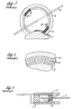
- an encoder module 1 provides a collimated light beam and has light detectors 7 to receive the light beam after modulation by a code wheel 3.
- a light emitting diode (LED) 9 provides light having a preferred wave length of approximately 700 nanometers; however, any frequency of electromagnetic radiation having a wave length substantially shorter than the relevant dimensions of the encoder may be utilized. For example, infrared light is commonly used.
- An emitter lens 11 is positioned to transmit the light from the LED 9.
- the code wheel 3 of FIGS. 1 and 2 is concentrically mounted on a shaft 5 to rotate with the shaft and modulate the light beam with an optical track 17.
- the track 17 has alternating light-transmissive sections or windows 13 and non-light-transmissive sections or spokes 15 of a unit width equal to the width of a window.
- One transmissive section and one non-transmissive section make up one pitch of the code wheel.
- the alternating sections 13, 15 block or admit light from the LED, thereby illuminating or blocking light passing to the photodetectors.
- the code wheel has 500 transmissive sections and an equal number of non-transmissive sections. These sections are trapezoidal in shape since they are located immediately adjacent to one another on a circular track.
- An exemplary nominal width of each transmissive section is 62 microns, and the radial length of each section is 750 microns.
- the code wheel is preferably made of a durable, optically opaque material, such as stainless steel, and has a diameter of approximately 22 millimeters.
- the transmissive sections may comprise holes masked and etched through the disk.
- a group of four light detectors 7 has approximately the same size and shape of one transmissive section and one non-transmissive section on the code wheel.
- Individual detectors 7a to 7b have a trapezoidal shape with an exemplary maximum width of 48 microns, a minimum width of approximately 45 microns with a gap of about 8 microns between the individual light detectors.
- the light detectors preferably comprise photodiodes fabricated on a semiconductor chip using standard bipolar semiconductor technology. As illustrated in Figure 4, a group of light detectors are placed in a one-dimensional array as close to one another as the bipolar semiconductor technology will allow.
- Dummy photodiodes 10 and 12 are located on each end of the array to minimize the effect of stray light on the functioning light detectors 7a-7d.
- the photodiodes are arranged in an arc having the same radius as the code track on the code wheel.
- an index pulse from a single track code wheel is easily achieved using this known apparatus employing photo interrupters or magnetic sensors, but is difficult using push-pull circuitry.
- the index pulse generated has a logic level which differs as the direction of rotation differs.
- Figure 5b includes a representation of a segment of a code wheel as a flat strip having alternating adjacent windows and spokes each having a unit width. Each pair of one window and one spoke represents one timing cycle of length 20 also called length T.
- An index window 19 having a width of three units is provided in the wheel.
- a light source comprising a pair of LEDs 26a, 26b which may be mounted in a housing 28.
- a pair of photodiodes 30a, 30b in a common housing 32.
- One LED 26a is vertically aligned with one photodiode 30a, and the other LED 26b is vertically aligned with the other photodiode 30b.
- first LED 26a and photodiode 30a are offset laterally from the second LED 26b and photodiode 30b by a distance 22 equal to distance T divided by four.
- the apparatus of Figure 1b thereby creates a two-channel arrangement in which the first photodiode 30a generates one data channel having a waveform output 23a, and the second photodiode 30b generates a second data channel having waveform output 23b.
- Waveform 23b is 90 electrical degrees out of phase from waveform 23a due to the lateral separation of the photodiodes 30a, 30b.
- a low level index pulse 24 is generated when the wheel passes in front of the photodiodes.
- the direction of rotation of the wheel can be determined by sensing which photodiode generates a low pulse 24 first, since in one direction the index window of the wheel will pass photodiode 30a first, while in the other direction photodiode 30b will encounter the index window 19 first.
- Push-pull circuitry may be added to the apparatus of Figure 1b, resulting in the apparatus of Figure 6a, 6b.
- the code wheel is unmodified, but the LEDs 60a, 60b are each aligned over a window or spoke, separated by a distance 64 equal to T divided by two.
- the photodiodes 62a, 62b are similarly offset by a distance 64, and each produces separate output pulses electrically connected to input lines 66a, 66b of a buffer circuit; these output pulses are of opposite logic level. That is, when a window passes the photodiodes a low signal is generated by photodiode 62a, but a high pulse is generated by photodiode 62b.
- An operational amplifier 68 combines these signals on a single output line 69.
- Figures 6c and 6d illustrate the direction of movement of the wheel and the corresponding output signals from the apparatus of Figure 6a, 6b.
- the wheel includes an index position 70.
- the wheel is traveling rightward in the direction of arrow 72. Since the index window passes photodiode 62a first, photodiode 62a conducts continuously while the index window is overhead, generating a long high-level index pulse 76.
- the wheel travels leftward in the direction of arrow 73. Therefore photodiode 62b first encounters the window, resulting in generating of a low-level index pulse 80.
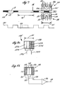
- the apparatus of Figure 7 comprising a code wheel 103, an LED assembly or illumination means 100, and a photodetector assembly or photodetector means 108.
- Code wheel 3 includes an index window 116 formed by removing a spoke 115 from wheel 103, resulting in creation of a window 116 having a length 118 of three units.
- the LED assembly 100 is preferably mounted in a single housing 100' having a length 101 of two units, that is, less than the length 118.
- the LED assembly includes a first LED 102, a second LED 104, and a third LED 106, although a single LED having a vertically collimated lens may be used.
- a collimated lens is required to ensure that light is directed straight at the photodetector assembly 108.
- the photodetector assembly 108 similarly is preferably encapsulated in a single housing 109 having a two-unit length 101.
- the housing may comprise a single integrated circuit.
- the photodetector assembly includes a first photodetector 110, a second photodetector 112, and a third photodetector 114.
- the first photodetector 110 has a unit width and is located between the other two photodetectors 112 and 114, which are each fabricated with a width of one-half unit. Thus, the combined width of the three photodetectors is two units.
- the length 118 of the index window is 1.5 times the length of the LED and photodetector assemblies.
- the photodetector assembly may be constructed in the form of a single integrated circuit having a flat, generally rectangular body 128 divided into four separate photodetectors 110a, 110b, 112, 114 each having a half-unit width.
- the center photodetectors 110a and 110b are wired together to produce a single output line 132.
- these two center photodetectors 110a, 110b form a unit-width center photodetector panel.
- Photodetectors 112, 114 are each a half unit wide.
- the outer pair of photodetectors are also connected together by a single output line 134.
- the output lines 132, 134 from the photodetectors are connected to a buffer circuit 136 in known manner which produces a single output on line 138.
- a conventional two-element push-pull photodetector assembly 108' may be constructed using a first photodetector having photodetector panels 129a, 129b and a second adjacent photodetector comprising detector panels 129c, 129d. Each panel 129a-129d has a half unit width. The total width of the photodetector assembly is two units. Output is provided on a first photodetector output line 139a connected to one pair of photodetectors 129a, 129b and a second output line 139b wired to the other pair of photodetectors 129c, 129d.
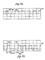
- FIG. 9a illustrates the waveform output of the side-by-side 108' of Figure 8a when the wheel is moving in a clockwise direction.
- This waveform 140 includes a low-level index pulse 142 generated when the index window 118 passes the photodetectors.
- the distance between the trailing edge 144 of the prior pulse and the leading edge 146 of the next pulse is approximately three times the unit pulse width.
- FIG 9b the output waveform 150 of clockwise rotation of the wheel past the centered photodetector assembly 108 of Figure 8b is illustrated.
- This waveform 150 includes a low level index pulse 152 separated from the trailing edge 154 and the leading edge 156 of adjacent pulses by approximately three times the unit pulse width.
- Figure 9c shows an output waveform 160 resulting from counterclockwise rotation of the wheel when used with the side-by-side assembly.
- This waveform 160 includes a high-level index pulse 162 having an overall length measured from a start point 164 to an end point 166 of approximately three times the unit pulse width.
- the pulse is high-level rather than low-level as is pulse 142 when the wheel rotates clockwise.
- Figure 9d shows a waveform 170 generated by the detector assembly 108 of Figure 8b during counterclockwise rotation of the wheel.
- the index pulse 172 remains at a low level, the same as the pulse 152 when the wheel is rotating clockwise.
- the pulse 172 measured from start point 174 to end point 176, has an overall length approximately three times the unit pulse width.
- output waveforms 150, 170 show that output of the invention apparatus remains consistent regardless of the direction of rotation of the code wheel.
- Use of the invention eliminates the need to incorporate, in an end-user product, additional circuitry to sense the direction of the code wheel and to invert the logic level of the index pulse depending on the direction of rotation of the code wheel. This results in a simplified product which can be manufactured at lower cost.
- the direction of rotation of the wheel may be determined in several ways. First, in applications in which a single microprocessor controls the direction of a motor turning a shaft on which the wheel is mounted, the microprocessor will inherently "know" the direction of rotation. Second, in applications in which the shaft is entirely independent of the photodetectors, such as automotive applications, in combination with the invention an additional push-pull direction detector is used, such as the detector of Figure 5a or 6a. This additional direction detector may use the same source of illumination as the index detector of the invention. The direction detector may also use a separate, non-indexed data track on the code wheel.
- the code wheel is referred to as being located “between” the light source and the photodetectors.
- the term “between” also extends to an arrangement in which both the light source and the photodetectors are located on the same side of the code wheel.
- the code wheel may comprise a solid disk having plural reflective regions, serving as windows, interleaved with opaque, non-reflective "spokes," so that light from the light source reflects off the reflective windows and into the photodetectors.
- the three unit wide window discussed herein is functionally the same as a missing spoke.
Landscapes
- Physics & Mathematics (AREA)
- General Physics & Mathematics (AREA)
- Optical Transform (AREA)
- Analogue/Digital Conversion (AREA)
Description
- This invention generally relates to position sensors or encoders, such as optical shaft angle encoders, which produce discrete electrical signals indicative of the angular position of a shaft. In particular, the present invention improves generation of an index pulse or index location at a consistent logical level regardless of the direction of rotation of the shaft.
- Incremental optical motion encoders are used to resolve the position and movement of an object along a particular route. Such encoders generally include a light source for emitting a light beam, light modulation means for modulating the light beam in response to movement of the object along the route, and detection means for receiving modulated light and for producing discrete electrical signals representing detection of light by the detectors. As the light is modulated in response to the movement of the object, the stream of electrical signals from the detector assembly produces a continuous wave form usually resembling a square wave. The position of the object along its route determines the position of each signal in the wave form. The phase of the wave form differs depending upon the location of the object. Thus, signals from the detectors can be used to indicate a change in location of the object along the route. Two or more out-of-phase signals from separate detectors can be used to detect both change in location and change of direction of movement.
- For an incremental motion encoder to indicate the absolute position or location of the object along its route, an index pulse is generated at least once along the route. The incremental signals can be used to count incremental movement from the index pulse. If the position of the object is known at the time the index pulse is generated, the absolute position of the object at any place along the route can be determined.
- Therefore, to provide an indication of absolute position, change in location and direction of movement, an incremental encoder usually requires three channels of information. Two channels are derived from two or more out-of-phase encoder signals that are produced throughout the route of the object, and the third is an index signal produced at least once along the route at a known position of the object.
- In a typical embodiment, such a position encoder or movement detector is used to measure the angular position of a shaft. Depending on the use of such a shaft angle encoder, a high degree of resolution and accuracy may be needed; for example, in automotive crankshaft angle measurement applications, a resolution of 2000 increments per revolution of the shaft may be necessary. Accuracy of the correlation between the signal from the encoder and the actual mechanical position of the shaft is also important. Mechanical alignment discrepancies can adversely affect accuracy as can electrical noise, due to the very small dimensions of the code wheel, the transmissive sections and the non-transmissive sections.
- To accurately detect the index pulse, a push-pull electronic arrangement may be used to determine the location of the index pulse. In such an arrangement, two photodetectors are arranged laterally adjacent one another in vertical alignment with a light source; a spoked circular code wheel fixed to the shaft separates the light source and the detectors. When one of the detectors is illuminated, a logic signal of one sense, such as 1, is produced. When a spoke on the code wheel occults the illumination, the opposite logic signal is produced, such as a logical 0. When the index window passes over the detectors, one detector will generate a logic 1 of long duration, followed an instant later by a logic 1 from the second detector. The direction of travel of the code wheel may be determined by sensing which detector is first to generate a long-duration logic 1.
- Another desirable feature of code wheel encoders is to determine the index location regardless of the direction of rotation of the code wheel or shaft. Since code wheels ordinarily can rotate both clockwise and counter-clockwise, it is desirable that the encoder apparatus produce an index pulse output at a consistent logic level regardless of the direction of rotation. In conventional code wheel encoders employing push-pull optics and electronics using two adjacent light sources and two adjacent detectors, the logical value of the index pulse is different depending on the direction of rotation. Thus, if the wheel is rotating clockwise, such conventional circuits will produce a low logic value index pulse, and when the code wheel is rotating counter-clockwise, the conventional circuit will produce a high-logic value index pulse. This feature is undesirable, because the circuitry receiving the index pulse must accommodate for both high and low logical values. Such accommodation ordinarily requires additional undesirable hardware.
- US-A-4,782,229 discloses a photoelectric measuring system which includes a plurality of photodetectors disposed adjacent one another and designed so as to reduce harmonics in the output signals and include wider photodetectors interposed between more narrow photodetectors.
- Thus, it is desirable to provide an optical encoder apparatus which produces an index pulse having the same logic value regardless of the direction of rotation of the code wheel. Preferably, this is provided by modifying the photo receptor or photodetector assembly rather than changing external hardware, and using a conventional push-pull encoder.
- According to the invention, there is provided a position encoder as specified in claim 1.
- Preferably one detector has a unit width, and the other two detectors each have a one-half unit width.
- In an exemplary embodiment, the light interruption means comprises a movable code member mounted between the illumination source and the photodetectors for alternately transmitting or blocking the illumination source upon movement. The code member also includes means for indexing the code member. The second and third photodetectors are preferably arranged to be occulted by a spoke when the first photodetector is illuminated by the light source. Each photodetector can produce a logic value in response to detection of light or the absence of light.
- In an exemplary embodiment, the code member comprises a code wheel with a circumferential track comprising a plurality of alternating windows and spokes for alternately transmitting or blocking the illumination means upon movement of the code wheel. Each window and each spoke has a unit width. The means for indexing the code wheel comprises an index window having a three-unit width on the track. The index window, in effect, is formed by removing a spoke from between two adjacent windows. The encoder preferably includes a circuit for processing the photodetector output signals. The circuit comprises a buffer circuit for processing the output signals, having a first input connected to the output of the second and third photodetectors, and a second input connected to the output of the first photodetector.
- Use of the invention eliminates the need to incorporate, in an end-user product, additional circuitry to sense the direction of the code wheel and to invert the logic level of the index pulse depending on the direction of rotation of the code wheel. This results in a simplified product which can be manufactured at lower cost.Applications for this technique include automotive equipment location sensing, photocopiers, and other light industrial equipment.
- The foregoing features of the present invention will be better understood upon consideration of the following detailed description of certain preferred embodiments taken in conjunction with the accompanying drawings in which:
- FIG. 1 is a front perspective view of an exemplary code wheel assembly;
- FIG. 2 is a partial view of the face of the code wheel of FIG. 1;
- FIG. 3 is a partial section view of the light source and receptor apparatus of FIG. 1;
- FIG. 4 is an enlarged partial view of the code wheel and receptor apparatus of FIG. 1;
- FIG. 5a is a partial schematic cross section of a prior art code wheel and detector assembly;
- FIG. 5b is a schematic representation of the code wheel of FIG. 5a and the wave form output by the apparatus of FIG. 5a;
- FIG. 6a is a schematic cross section of a second prior art encoder apparatus;
- FIG. 6b is a schematic diagram of output hardware of the apparatus of FIG. 6a;
- FIG. 6c is a schematic cross section of the apparatus of FIG. 6a in operation in a first direction of rotation;
- FIG. 6d is a schematic cross section of the apparatus of FIG. 6a operated in a second direction of rotation;
- FIG. 7 is a side elevation of the apparatus of the present invention and a corresponding output waveform;
- FIG. 8a and 8b are plan views of two embodiments of the detector of FIG. 7; and
- FIG. 9a, 9b, 9c, 9d are schematic representations of the output wave forms of the detectors of FIG. 8a and 8b.
- An optical encoder useful to understand the present invention is described in U.S. Patent No. 4,691,101 (Leonard). Other shaft angle encoders are described, for example, in U.S. Patents Nos. 4,259,570, 4,266,125, 4,451,731 and 4,691,101. Figures 1-4 herein relate most particularly to the Leonard patent and the subject therein. Figure 4 is representative of the prior art as disclosed in the Leonard patent.
- In Figures 1-3, an encoder module 1 provides a collimated light beam and has light detectors 7 to receive the light beam after modulation by a
code wheel 3. A light emitting diode (LED) 9 provides light having a preferred wave length of approximately 700 nanometers; however, any frequency of electromagnetic radiation having a wave length substantially shorter than the relevant dimensions of the encoder may be utilized. For example, infrared light is commonly used. An emitter lens 11 is positioned to transmit the light from the LED 9. - The
code wheel 3 of FIGS. 1 and 2 is concentrically mounted on a shaft 5 to rotate with the shaft and modulate the light beam with anoptical track 17. Thetrack 17 has alternating light-transmissive sections orwindows 13 and non-light-transmissive sections orspokes 15 of a unit width equal to the width of a window. One transmissive section and one non-transmissive section make up one pitch of the code wheel. As the wheel rotates, the alternatingsections - In an exemplary embodiment, the code wheel has 500 transmissive sections and an equal number of non-transmissive sections. These sections are trapezoidal in shape since they are located immediately adjacent to one another on a circular track. An exemplary nominal width of each transmissive section is 62 microns, and the radial length of each section is 750 microns. The code wheel is preferably made of a durable, optically opaque material, such as stainless steel, and has a diameter of approximately 22 millimeters. The transmissive sections may comprise holes masked and etched through the disk.
- In one embodiment illustrated in Leonard and reproduced herein in Figure 4, several groups of four
light detectors 7a to 7d are provided. A group of four light detectors 7 has approximately the same size and shape of one transmissive section and one non-transmissive section on the code wheel.Individual detectors 7a to 7b have a trapezoidal shape with an exemplary maximum width of 48 microns, a minimum width of approximately 45 microns with a gap of about 8 microns between the individual light detectors. The light detectors preferably comprise photodiodes fabricated on a semiconductor chip using standard bipolar semiconductor technology. As illustrated in Figure 4, a group of light detectors are placed in a one-dimensional array as close to one another as the bipolar semiconductor technology will allow. Dummy photodiodes 10 and 12 are located on each end of the array to minimize the effect of stray light on the functioninglight detectors 7a-7d. In a shaft angle encoder, the photodiodes are arranged in an arc having the same radius as the code track on the code wheel. - Using such an arrangement of four light detectors, four output signals are produced having the same wave form shape but offset from one another by multiples of 90 electrical degrees. These four signals in quadrature are compared for determining the amount and direction of rotation of code wheel.
- In an embodiment mentioned in the Leonard patent, there are several groups of four light detectors. The signals from the "A" detectors in the groups are combined; similarly signals from the "B" detectors are summed, etc. By using plural detector groups, a larger detector area is illuminated, providing greater signal strength while maintaining high resolution. Regardless of the number of groups, there are four signals and two channels of information.
- Generating an index pulse from a single track code wheel is easily achieved using this known apparatus employing photo interrupters or magnetic sensors, but is difficult using push-pull circuitry. In particular, when a single track code wheel is used with a pair of sensors coupled using push-pull electronics, the index pulse generated has a logic level which differs as the direction of rotation differs.
- For example, one known technique for detecting the index position of a code wheel having a single track is to use the apparatus of Figure 5a which produces output waveforms shown in Figure 5b. Figure 5b includes a representation of a segment of a code wheel as a flat strip having alternating adjacent windows and spokes each having a unit width. Each pair of one window and one spoke represents one timing cycle of
length 20 also called length T. Anindex window 19 having a width of three units is provided in the wheel. Mounted above the wheel is a light source comprising a pair ofLEDs 26a, 26b which may be mounted in a housing 28. Below the wheel is a pair ofphotodiodes 30a, 30b in acommon housing 32. OneLED 26a is vertically aligned with onephotodiode 30a, and the other LED 26b is vertically aligned with the other photodiode 30b. - However, the
first LED 26a andphotodiode 30a are offset laterally from the second LED 26b and photodiode 30b by adistance 22 equal to distance T divided by four. The apparatus of Figure 1b thereby creates a two-channel arrangement in which thefirst photodiode 30a generates one data channel having awaveform output 23a, and the second photodiode 30b generates a second data channel havingwaveform output 23b.Waveform 23b is 90 electrical degrees out of phase fromwaveform 23a due to the lateral separation of thephotodiodes 30a, 30b. A lowlevel index pulse 24 is generated when the wheel passes in front of the photodiodes. - As a result, the direction of rotation of the wheel can be determined by sensing which photodiode generates a
low pulse 24 first, since in one direction the index window of the wheel will passphotodiode 30a first, while in the other direction photodiode 30b will encounter theindex window 19 first. - Push-pull circuitry may be added to the apparatus of Figure 1b, resulting in the apparatus of Figure 6a, 6b. In this arrangement, the code wheel is unmodified, but the LEDs 60a, 60b are each aligned over a window or spoke, separated by a
distance 64 equal to T divided by two. The photodiodes 62a, 62b are similarly offset by adistance 64, and each produces separate output pulses electrically connected to inputlines 66a, 66b of a buffer circuit; these output pulses are of opposite logic level. That is, when a window passes the photodiodes a low signal is generated by photodiode 62a, but a high pulse is generated by photodiode 62b. An operational amplifier 68 combines these signals on asingle output line 69. - Figures 6c and 6d illustrate the direction of movement of the wheel and the corresponding output signals from the apparatus of Figure 6a, 6b. The wheel includes an
index position 70. In Figure 6c, the wheel is traveling rightward in the direction of arrow 72. Since the index window passes photodiode 62a first, photodiode 62a conducts continuously while the index window is overhead, generating a long high-level index pulse 76. In contrast, in Figure 6d, the wheel travels leftward in the direction of arrow 73. Therefore photodiode 62b first encounters the window, resulting in generating of a low-level index pulse 80. - This discrepancy in the logic level of the
pulses code wheel 103, an LED assembly or illumination means 100, and a photodetector assembly or photodetector means 108. -
Code wheel 3 includes anindex window 116 formed by removing aspoke 115 fromwheel 103, resulting in creation of awindow 116 having alength 118 of three units. - The
LED assembly 100 is preferably mounted in a single housing 100' having alength 101 of two units, that is, less than thelength 118. The LED assembly includes afirst LED 102, asecond LED 104, and athird LED 106, although a single LED having a vertically collimated lens may be used. A collimated lens is required to ensure that light is directed straight at thephotodetector assembly 108. - The
photodetector assembly 108 similarly is preferably encapsulated in asingle housing 109 having a two-unit length 101. The housing may comprise a single integrated circuit. The photodetector assembly includes afirst photodetector 110, asecond photodetector 112, and athird photodetector 114. Thefirst photodetector 110 has a unit width and is located between the other twophotodetectors length 118 of the index window is 1.5 times the length of the LED and photodetector assemblies. - As indicated in Figure 8b, the photodetector assembly may be constructed in the form of a single integrated circuit having a flat, generally
rectangular body 128 divided into fourseparate photodetectors single output line 132. Thus, these two center photodetectors 110a, 110b form a unit-width center photodetector panel.Photodetectors single output line 134. Theoutput lines buffer circuit 136 in known manner which produces a single output online 138. - Alternatively, as shown in Figure 8a, a conventional two-element push-pull photodetector assembly 108' may be constructed using a first photodetector having photodetector panels 129a, 129b and a second adjacent photodetector comprising
detector panels 129c, 129d. Each panel 129a-129d has a half unit width. The total width of the photodetector assembly is two units. Output is provided on a first photodetector output line 139a connected to one pair of photodetectors 129a, 129b and a second output line 139b wired to the other pair ofphotodetectors 129c, 129d. - Using this apparatus, four
different output waveforms photodetector assembly 108, 108' used and the direction of rotation of the wheel; thesewaveforms - Attention is invited to Figure 9a which illustrates the waveform output of the side-by-side 108' of Figure 8a when the wheel is moving in a clockwise direction. This
waveform 140 includes a low-level index pulse 142 generated when theindex window 118 passes the photodetectors. The distance between the trailingedge 144 of the prior pulse and theleading edge 146 of the next pulse is approximately three times the unit pulse width. - In Figure 9b the
output waveform 150 of clockwise rotation of the wheel past the centeredphotodetector assembly 108 of Figure 8b is illustrated. Thiswaveform 150 includes a lowlevel index pulse 152 separated from the trailingedge 154 and theleading edge 156 of adjacent pulses by approximately three times the unit pulse width. - Figure 9c shows an
output waveform 160 resulting from counterclockwise rotation of the wheel when used with the side-by-side assembly. Thiswaveform 160 includes a high-level index pulse 162 having an overall length measured from astart point 164 to anend point 166 of approximately three times the unit pulse width. However, because the direction of rotation has reversed with respect to Figure 9a, the pulse is high-level rather than low-level as is pulse 142 when the wheel rotates clockwise. - Figure 9d shows a waveform 170 generated by the
detector assembly 108 of Figure 8b during counterclockwise rotation of the wheel. Although the rotation direction of the wheel is reversed with respect to Figure 9b, theindex pulse 172 remains at a low level, the same as thepulse 152 when the wheel is rotating clockwise. Thepulse 172, measured fromstart point 174 toend point 176, has an overall length approximately three times the unit pulse width. - Thus,
output waveforms 150, 170 show that output of the invention apparatus remains consistent regardless of the direction of rotation of the code wheel. Use of the invention eliminates the need to incorporate, in an end-user product, additional circuitry to sense the direction of the code wheel and to invert the logic level of the index pulse depending on the direction of rotation of the code wheel. This results in a simplified product which can be manufactured at lower cost. - As is known in the art, the direction of rotation of the wheel may be determined in several ways. First, in applications in which a single microprocessor controls the direction of a motor turning a shaft on which the wheel is mounted, the microprocessor will inherently "know" the direction of rotation. Second, in applications in which the shaft is entirely independent of the photodetectors, such as automotive applications, in combination with the invention an additional push-pull direction detector is used, such as the detector of Figure 5a or 6a. This additional direction detector may use the same source of illumination as the index detector of the invention. The direction detector may also use a separate, non-indexed data track on the code wheel.
- In the foregoing discussion certain specific technical terms are used for the sake of clarity; however, the invention should not be limited to the specific terms so selected. For example, throughout this application, and in the claims, the code wheel is referred to as being located "between" the light source and the photodetectors. However, the term "between" also extends to an arrangement in which both the light source and the photodetectors are located on the same side of the code wheel. In such an arrangement, the code wheel may comprise a solid disk having plural reflective regions, serving as windows, interleaved with opaque, non-reflective "spokes," so that light from the light source reflects off the reflective windows and into the photodetectors. Additionally, the three unit wide window discussed herein is functionally the same as a missing spoke.
Claims (8)
- A position encoder for a rotatable shaft comprising a radiation source; first, second and third radiation detectors (110,112,114), the first (110) being wider than and lying between the other two (112,114); movable code means associated with the shaft between the sources and the detectors, and including a succession of regular radiation apertures (13) through which radiation may pass and an irregular radiation aperture (118) wider than the regular apertures so as to form an index point; and an output circuit comprising a first input coupled to both the second and third detectors and a second input coupled to the third detector, the couplings being such as to provide the same output logic pattern at the output circuit irrespective of the direction of motion of the apertures across the detectors.
- A position encoder as claimed in claim 1, wherein said irregular aperture (118) is three times as wide as a regular aperture (13).
- A position encoder as claimed in any preceding claim wherein said movable code means is a circular disc with regular circumferential apertures and intervening spokes of the same unit width.
- A position encoder as claimed in any preceding claim wherein the first detector (110) is twice as wide as the second and third detectors (112,114) which are of equal width.
- A position encoder as claimed in any preceding claim, wherein said radiation source comprises first, second and third sources (102,104,106), the first (102) being wider than and lying between the other two (104,106).
- A position encoder as claimed in claims 3, 4 or 5, wherein the first detector (110), the first source (102) and the regular apertures (13) all have the same unit width.
- A position encoder as claimed in any preceding claim, inciuding circuit means (136) for receiving and processing output signals from the detectors, said circuit means comprising a buffer circuit receiving linked outputs of the second and third detectors at one input and the output of the first detector at its other input.
- A position encoder as claimed in any preceding claim wherein the sources and detectors are respectively light-emitting diodes and photodetectors.
Applications Claiming Priority (2)
| Application Number | Priority Date | Filing Date | Title |
|---|---|---|---|
| US686677 | 1991-04-17 | ||
| US07/686,677 US5148020A (en) | 1991-04-17 | 1991-04-17 | Optical encoder with photodetectors of width equal to and one-half of code wheel's window and spoke width |
Publications (3)
| Publication Number | Publication Date |
|---|---|
| EP0509828A2 EP0509828A2 (en) | 1992-10-21 |
| EP0509828A3 EP0509828A3 (en) | 1993-05-12 |
| EP0509828B1 true EP0509828B1 (en) | 1996-01-31 |
Family
ID=24757286
Family Applications (1)
| Application Number | Title | Priority Date | Filing Date |
|---|---|---|---|
| EP92303455A Expired - Lifetime EP0509828B1 (en) | 1991-04-17 | 1992-04-16 | Optical encoder with improved indux pulse |
Country Status (4)
| Country | Link |
|---|---|
| US (1) | US5148020A (en) |
| EP (1) | EP0509828B1 (en) |
| JP (1) | JP3366347B2 (en) |
| DE (1) | DE69207941T2 (en) |
Families Citing this family (17)
| Publication number | Priority date | Publication date | Assignee | Title |
|---|---|---|---|---|
| US5324934A (en) * | 1991-05-01 | 1994-06-28 | Megamation Incorporated | Fiberoptic encoder for linear motors and the like |
| US5557450A (en) * | 1994-01-04 | 1996-09-17 | Primax Electronics Ltd. | Optical rotation encoder for X-Y direction input device |
| JPH08213447A (en) * | 1995-02-06 | 1996-08-20 | Tokyo Electron Ltd | Transfer object detection device |
| US5640007A (en) * | 1995-06-21 | 1997-06-17 | Limitorque Corporation | Optical encoder comprising a plurality of encoder wheels |
| JPH09222435A (en) * | 1995-12-11 | 1997-08-26 | Nippon Signal Co Ltd:The | Rotation stop sensor |
| US5982551A (en) * | 1998-09-25 | 1999-11-09 | Wang; Ching-Shun | Optical encoder wheel with split lens ring |
| US6069464A (en) * | 1998-10-01 | 2000-05-30 | Umax Data Systems Inc. | Driving apparatus for an image processing system |
| US6281490B1 (en) * | 1999-03-04 | 2001-08-28 | Continental Teves, Inc. | Method and device for generating distinguishable signals and method of distinguishing signals of similar shape |
| US6396052B1 (en) | 2000-04-07 | 2002-05-28 | Lexmark International, Inc. | High precision analog encoder system |
| US6653619B2 (en) | 2000-09-15 | 2003-11-25 | Agilent Technologies, Inc. | Optical motion encoder with a reflective member allowing the light source and sensor to be on the same side |
| DE102005053560B4 (en) * | 2005-01-14 | 2012-07-12 | Novoferm Tormatic Gmbh | Electromechanical drive for a gate or the like |
| US7211786B1 (en) * | 2006-03-16 | 2007-05-01 | Avago Technologies General Ip (Singapore) Pte. Ltd. | Reflective linear encoder having controlled detector to code strip distance |
| FR2937129B1 (en) * | 2008-10-10 | 2012-11-16 | Thales Sa | OPTICAL ENCODER |
| US8097842B2 (en) | 2009-05-31 | 2012-01-17 | Avago Technologies Ecbu Ip (Singapore) Pte. Ltd. | High resolution single track optical encoder |
| US8525102B2 (en) * | 2011-02-15 | 2013-09-03 | Avago Technologies General Ip (Singapore) Pte. Ltd. | Optical encoding system and optical encoder having an array of incremental photodiodes and an index photodiode for use in an optical encoding system |
| US9354087B2 (en) | 2013-01-09 | 2016-05-31 | Avago Technologies General Ip (Singapore) Pte. Ltd. | Single track three-channel encoder with differential index |
| EP3276680A1 (en) * | 2017-01-25 | 2018-01-31 | Siemens Schweiz AG | Optical smoke detection based on the two colour principle using a light emitting diode with an led chip for light emission and with a light converter for converting a part of the emitted light to longer wave light |
Family Cites Families (5)
| Publication number | Priority date | Publication date | Assignee | Title |
|---|---|---|---|---|
| US4266125A (en) * | 1978-12-21 | 1981-05-05 | Hewlett-Packard Company | Optical shaft angle encoder |
| US4654525A (en) * | 1982-08-31 | 1987-03-31 | Sharp Kabushiki Kaisha | Optical rotary encoder |
| US4691101A (en) * | 1985-06-19 | 1987-09-01 | Hewlett-Packard Company | Optical positional encoder comprising immediately adjacent detectors |
| JPS6255511A (en) * | 1985-09-05 | 1987-03-11 | Sharp Corp | Rotary encoder |
| DE3616144A1 (en) * | 1986-05-14 | 1987-11-19 | Heidenhain Gmbh Dr Johannes | PHOTOELECTRICAL MEASURING DEVICE |
-
1991
- 1991-04-17 US US07/686,677 patent/US5148020A/en not_active Expired - Lifetime
-
1992
- 1992-04-16 EP EP92303455A patent/EP0509828B1/en not_active Expired - Lifetime
- 1992-04-16 DE DE69207941T patent/DE69207941T2/en not_active Expired - Lifetime
- 1992-04-17 JP JP09755992A patent/JP3366347B2/en not_active Expired - Lifetime
Also Published As
| Publication number | Publication date |
|---|---|
| DE69207941T2 (en) | 1996-06-05 |
| JP3366347B2 (en) | 2003-01-14 |
| JPH05141987A (en) | 1993-06-08 |
| DE69207941D1 (en) | 1996-03-14 |
| EP0509828A3 (en) | 1993-05-12 |
| EP0509828A2 (en) | 1992-10-21 |
| US5148020A (en) | 1992-09-15 |
Similar Documents
| Publication | Publication Date | Title |
|---|---|---|
| US5241172A (en) | Variable pitch position encoder | |
| US5148020A (en) | Optical encoder with photodetectors of width equal to and one-half of code wheel's window and spoke width | |
| EP0206656B1 (en) | Optical encoder | |
| US8525102B2 (en) | Optical encoding system and optical encoder having an array of incremental photodiodes and an index photodiode for use in an optical encoding system | |
| EP0770850B1 (en) | Displacement information detection apparatus | |
| US4920259A (en) | Apparatus for producing a phase insensitive index pulse for motion encoders | |
| US6175109B1 (en) | Encoder for providing incremental and absolute position data | |
| US6727493B2 (en) | Multiple resolution photodiode sensor array for an optical encoder | |
| EP0419172B1 (en) | Optical encoders | |
| US7348545B2 (en) | System and method for optical encoding on two opposed surfaces of a pattern medium | |
| JP3262842B2 (en) | Optical encoder | |
| US7262714B2 (en) | Interpolating encoder utilizing a frequency multiplier | |
| US5013910A (en) | Shaft angle encoder with a symmetrical code wheel | |
| US5497226A (en) | Quadrature diffractive encoder | |
| US9354087B2 (en) | Single track three-channel encoder with differential index | |
| CN100526809C (en) | Transmissive optical encoder | |
| JPS60131470A (en) | Optical fiber vector detector | |
| SU1714342A1 (en) | Displacement transducer | |
| JPH08201115A (en) | Rotary encoder |
Legal Events
| Date | Code | Title | Description |
|---|---|---|---|
| PUAI | Public reference made under article 153(3) epc to a published international application that has entered the european phase |
Free format text: ORIGINAL CODE: 0009012 |
|
| AK | Designated contracting states |
Kind code of ref document: A2 Designated state(s): DE FR GB |
|
| PUAL | Search report despatched |
Free format text: ORIGINAL CODE: 0009013 |
|
| AK | Designated contracting states |
Kind code of ref document: A3 Designated state(s): DE FR GB |
|
| 17P | Request for examination filed |
Effective date: 19931102 |
|
| 17Q | First examination report despatched |
Effective date: 19941123 |
|
| GRAA | (expected) grant |
Free format text: ORIGINAL CODE: 0009210 |
|
| AK | Designated contracting states |
Kind code of ref document: B1 Designated state(s): DE FR GB |
|
| PG25 | Lapsed in a contracting state [announced via postgrant information from national office to epo] |
Ref country code: FR Effective date: 19960131 |
|
| REF | Corresponds to: |
Ref document number: 69207941 Country of ref document: DE Date of ref document: 19960314 |
|
| EN | Fr: translation not filed | ||
| PLBE | No opposition filed within time limit |
Free format text: ORIGINAL CODE: 0009261 |
|
| STAA | Information on the status of an ep patent application or granted ep patent |
Free format text: STATUS: NO OPPOSITION FILED WITHIN TIME LIMIT |
|
| 26N | No opposition filed | ||
| REG | Reference to a national code |
Ref country code: GB Ref legal event code: 732E |
|
| REG | Reference to a national code |
Ref country code: GB Ref legal event code: 732E |
|
| REG | Reference to a national code |
Ref country code: GB Ref legal event code: IF02 |
|
| REG | Reference to a national code |
Ref country code: GB Ref legal event code: 732E |
|
| REG | Reference to a national code |
Ref country code: GB Ref legal event code: 732E |
|
| PGFP | Annual fee paid to national office [announced via postgrant information from national office to epo] |
Ref country code: DE Payment date: 20100430 Year of fee payment: 19 |
|
| PGFP | Annual fee paid to national office [announced via postgrant information from national office to epo] |
Ref country code: GB Payment date: 20110413 Year of fee payment: 20 |
|
| PG25 | Lapsed in a contracting state [announced via postgrant information from national office to epo] |
Ref country code: DE Free format text: LAPSE BECAUSE OF NON-PAYMENT OF DUE FEES Effective date: 20111101 |
|
| REG | Reference to a national code |
Ref country code: DE Ref legal event code: R119 Ref document number: 69207941 Country of ref document: DE Effective date: 20111101 |
|
| REG | Reference to a national code |
Ref country code: GB Ref legal event code: PE20 Expiry date: 20120415 |
|
| PG25 | Lapsed in a contracting state [announced via postgrant information from national office to epo] |
Ref country code: GB Free format text: LAPSE BECAUSE OF EXPIRATION OF PROTECTION Effective date: 20120415 |