EP0508601B1 - Angled fixture and display assembly - Google Patents
Angled fixture and display assembly Download PDFInfo
- Publication number
- EP0508601B1 EP0508601B1 EP92302081A EP92302081A EP0508601B1 EP 0508601 B1 EP0508601 B1 EP 0508601B1 EP 92302081 A EP92302081 A EP 92302081A EP 92302081 A EP92302081 A EP 92302081A EP 0508601 B1 EP0508601 B1 EP 0508601B1
- Authority
- EP
- European Patent Office
- Prior art keywords
- display
- mounting bracket
- standard
- support arm
- distal end
- Prior art date
- Legal status (The legal status is an assumption and is not a legal conclusion. Google has not performed a legal analysis and makes no representation as to the accuracy of the status listed.)
- Expired - Lifetime
Links
Images
Classifications
-
- A—HUMAN NECESSITIES
- A47—FURNITURE; DOMESTIC ARTICLES OR APPLIANCES; COFFEE MILLS; SPICE MILLS; SUCTION CLEANERS IN GENERAL
- A47F—SPECIAL FURNITURE, FITTINGS, OR ACCESSORIES FOR SHOPS, STOREHOUSES, BARS, RESTAURANTS OR THE LIKE; PAYING COUNTERS
- A47F5/00—Show stands, hangers, or shelves characterised by their constructional features
- A47F5/08—Show stands, hangers, or shelves characterised by their constructional features secured to the wall, ceiling, or the like; Wall-bracket display devices
- A47F5/0807—Display panels, grids or rods used for suspending merchandise or cards supporting articles; Movable brackets therefor
Definitions
- This invention relates to product display racks and the fixtures which make up those racks, and, more particularly, to an improved fixture and display assembly for relatively flat products, wherein individual fixtures are angled in a predetermined orientation to enable optimum display and convenient stocking, removal and replacement of the products.
- This invention is directed toward overcoming disadvantages and shortcomings in prior art display devices and fixtures designed to support relatively planar products such as carpet samples, floor mats, sample books, posters, or the like in a space efficient manner which is conducive to optimum display of the products and access for stocking procedures as well as customer inspection.
- heretofore product display racks for items such as aftermarket retail automotive floor mats have generally included a series of horizontally disposed, vertically spaced, display rack supports upon which a plurality of projecting support rods were anchored. Respective rows of support rods were also spaced in a tiered, front to rear fashion, and a plurality of floor mats were hung on each outwardly extending rod in side-by-side relationship. In this arrangement, however, only the floor mat hanging on the front of each support rod was visible to the customer, and the number of floor mats which could be hung on each support rod was limited by the front to rear spacing between respective rows.
- U.S. patent 3,568,852 (which issued to F. Howard) discloses a rack support for sample books of carpet or the like comprising a carrier element for each sample book which assumes a predetermined angularity with regard to the support bar as a result of a projecting member located adjacent an opening in the carrier element. This projecting member contacts the support bar and maintains the desired angularity.
- this structure requires a support bar extending between a spaced apart pair of columns and which is sufficiently spaced from an adjacent wall surface or the like to enable the products to hang freely. Such arrangement would not easily be adaptable to the often limited space restrictions encountered in retail displays and merchandising applications. Additionally, the strength and rigidity of the display device would be difficult to insure, and convenient labeling and distinction of various products or product models is not provided.
- a clothes display stand shown in U.S. patent 4,813,552 (which issued to H. Walter) lacks sufficient structure for insuring a strong and rigid display fixture and assembly capable of optimally displaying a maximum number of products.
- the extension arms of the Walter clothes display stand are oriented at an angle relative to the wall elements and include grooves to receive the clothes hangers and orient the individual products parallel to the wall. Such orientation limits the number of products which can be placed on the supports, and limits the number of products which can be easily seen by potential customers.
- U.S. patent 4,449,686 (which issued to M. Kersey) illustrates a mounting bracket having a plurality of projections for supporting hooks of a garment hanger.
- This display fixture would suffer from many of the same deficiencies as the standard, multi-tiered display arrangement described above.
- the collapsible hanger for peg board type display panels set forth in U.S. patent 4,516,681 (which issued to A. Jahel) offers very limited support strength, and appears to be directed toward applications wherein relatively small, light products are to be supported.
- FR-A-2399823 discloses an angled display assembly having a plurality of product display fixtures selectively attached to and spaced along a polygonal display standard having a longitudinal axis and top and bottom portions, said fixtures each comprising an inverted, generally U-shaped mounting bracket, said bracket including a plurality of inwardly facing surfaces corresponding to and sized for slidable clamping over the top portions of said display standard, and a support arm extending outwardly from said mounting bracket and having proximal and distal ends, said distal end being attached to said proximal end and extending outwardly therefrom in a bent configuration.
- an angled display fixture having a mounting bracket with a longitudinal axis for removably attaching said fixture to a display rack and a support arm extending outwardly from said mounting bracket, said support arm comprising interconnected proximal and distal ends wherein said proximal end is attached to said mounting bracket and extends outwardly therefrom, characterised in that the distal end extends outwardly from said mounting bracket at a predetermined non-normal and non-parallel angle relative to said longitudinal axis, and in that a support lock extends downwardly from said mounting bracket and has a locking leg spaced from said support arm for locking interaction with said display rack.
- each of the display fixtures is attached to and spaced along a polygonal display standard to provide a display assembly.
- each of the display fixtures includes an inverted, U-shaped mounting bracket having a corresponding size and shape slidably to clamp over the display standard, with its support arm extending outwardly from the mounting bracket.
- the support lock extends downwardly from the mounting bracket and its locking leg interacts with the bottom portion of the standard to lock the display fixture in place, and to offset rotational moments imposed by products supported on the distal end of the support arm.
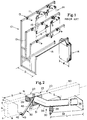
- FIG. 1 illustrates a prior art display rack 10 showing structures and features relatively common in the display industry.
- display rack 10 includes a plurality of horizontal display standards 11, supported in tiered, spaced relationship by a plurality of vertical columns 12.
- standards 11 mounted on standards 11 are a plurality of outwardly extending product fixtures 13 for supporting relatively planar products 14, such as automotive floor mats or the like.
- a dowel rod 16 is also shown to illustrate another common structure for hanging a plurality of flat or planar products 14.
- a tiered display rack such as illustrated in Fig. 1, can accommodate only a limited number of product pieces as a result of its structural limitations.
- the number of products e.g., floor mats 14
- the number of products which can be displayed is limited by the space available between adjacent tiers of standards 11, by the number of products which can be hung on any particular fixture 13, and by the number of products which can be placed side by side (i.e., limited by the width W of the individual products 14) within each tier.
- Fig. 1 demonstrates how only the top portions of the forward-most product 14 hanging on each fixture 13 can be seen from the front of the display.
- visual and physical access to the displayed products from the ends or sides of the display is not possible. Consequently, only a very limited number of products can be seen by a customer, and the overall impact of the display is adversely affected. Distinguishing features of various models of products, and the full variety of colors and sizes available, is not easily displayed or seen in such display rack arrangements.
- display rack 10 requires substantial display space volume, including a predetermined depth D, as illustrated. Such volume requirements and dimensional criticalities further limit the applications in which such racks can be advantageously utilized.
- stocking procedures and removal/replacement of products in the various tiers requires inconvenient reaching, and are complicated by interference between products 14 and closely adjacent products and display structure.
- placement of product 14 on one of the fixtures 13 in the most upper tier requires directing the bottom portion (15) of a product 14 into the space in addition to aligning a hanger structure with fixture 13.
- Such inconvenience often discourages customers from fully appreciating the differences in style, size, color, etc. of various products in the display, and from properly replacing removed products after examination.
- angular display fixture 20 has been developed for use in an optimum angled display assembly 60, as illustrated in Figs. 2-4.
- display fixture 20 is illustrated as including a mounting bracket 22 preferably comprising a U-shaped member 23 having a front surface 24, a rear surface 26, and a top surface 28.
- mounting bracket 22 is designed to correspond to and slidably clamp over the top portions of a display standard (50). While standard 50 may be provided in a variety of configurations, a polygonal shape is preferred to provide for stable mounting of a plurality of fixtures 20. Particularly, standard 50 is illustrated in phantom in Fig. 2 as a generally rectangular bar, as commonly used in a variety of support and display structures. Front, rear, and top surfaces (24, 26, and 28) of U-shaped member 23 correspond to and closely match the shape and size of the upper portions of standard 50 in order to facilitate slidable clamping of mounting bracket 22 thereover.
- a product support arm 30 extends outwardly from mounting bracket 22, and includes proximal end 31 and distal end 33.
- Proximal end 31 extends outwardly from front surface 24 along an axis N, which is preferably substantially perpendicular to the longitudinal axis A passing through the center of mounting bracket 22.
- Longitudinal axis A is also substantially coincident with the central longitudinal axis along the length of the display standard 50, onto which fixture 20 will be clamped.
- Distal end 33 of support arm 30 is attached to proximal end 31 at an interface area 34 in a bent configuration.
- distal end 33 is oriented at an angle ⁇ relative to longitudinal axis A, wherein the angle ⁇ is chosen to insure that distal end 33 will be oriented in a predetermined non-normal and non-parallel relationship to longitudinal axis A.
- Fig. 2 illustrates a "right-handed" fixture 20, wherein distal end 33 is bent to the right of its mounting bracket 22 (when viewing from the front of fixture 20).
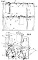
- Fig. 3 illustrates both right-handed fixtures 25 and left-handed fixtures 21, as an example of a display arrangement 60 which can be provided with the subject fixtures.
- Proximal end 31 serves as a standoff for distal end 33, effectively spacing the angled portion of display fixture 20 at a predetermined spacing distance S from mounting bracket 22 and display standard 50. Spacing S can be varied, as can angle ⁇ to accommodate products of varying sizes and display requirements.
- substantially planar products (e.g., floor mats or the like) 14 are supported along the distal end 33 of support arm 30 to provide enhanced visual and physical access to all of the products being displayed. Due to the angled orientation of products supported by fixtures 20 and 25, and due to the spacing S from standard 50, the width W of products 14 is no longer a limiting factor as to the number and spacing of products 14 which can be accommodated in a single angled display assembly 60. Moreover, as seen best in Fig. 4, portions of each of the products 14 displayed on any particular fixture 20 can be easily seen and are accessible for easy inspection and replacement from the front of the assembly 60.
- face plate 36 At the outermost end of distal end 33 is face plate 36, which extends laterally outwardly from distal end 33 to provide an effective retainer for products hung thereon. Additionally, face plate 36 can double as a convenient structure for interchangeable product identification, pricing, model indicia, or the like. Such identification (e.g., tag 37) facilitates use and maintenance of the assembly by retail employees and customers alike.
- a product stop 38 is preferably provided to prevent movement or migration of products 14 hung on arm 30 onto proximal end 31. It is also preferred that distal end 33 of arm 30 will be slightly upwardly inclined from interface area 34 to face plate 36, in clamped position. Such inclination prevents supported products from tending to slide toward face plate 36, and also accommodates possible downward flexing which may result from heaving product loading. Stop 38 also helps to maintain products 14 in their preferred angular orientation for optimum visual and physical access, and maintains proper spacing of product and alignment relative to the display backwall 62.
- a support lock 40 Extending downwardly from U-shaped member 23 is a support lock 40, including a transverse member or arm 42 and a rearwardly directed locking leg 43.
- Transverse arm 43 is connected to mounting bracket 22, such as by welding, and extends downwardly and away from support arm 30.
- Locking leg 43 is attached adjacent the distal end of transverse arm 43, and is shown as comprising a rod-like finger extending rearwardly to fit below standard 50 in locking relationship.
- the distal end of locking leg 43 is also preferably provided with a protective cap 45, made of plastic, rubber, or the like, to prevent scuffing or scratching of interacting surfaces, and for safety during handling and assembly procedures.
- Support lock 40 depends downwardly in a direction opposite to the outwardly extending direction of distal end 33 of support arm 30. As illustrated in Fig. 3, lock 40 will be oriented downwardly and to the right in the "left-handed” fixtures 21, while oriented to the left in “right-handed” fixtures 25. In this way, locking leg 43 is laterally offset a predetermined distance B from the center of mounting bracket 22 and proximal end 31 (e.g., axis N) of support arm 30, and underlies the bottom face "c" of standard 50 in use (see Fig. 2).
- U-shape member 23 will be slidably clamped over the upper portions (faces a, b, and d) of standard 50, and then rotated until locking leg 43 underlies and contacts lower face "c".
- support lock 40 obviates accidental removal of fixture 20 once placed on standard 50, and offsets and counteracts any rotational moment imposed on mounting bracket 22 by the cantilevered nature of support arm 30.
- Support lock 40 further enables relatively heavy loading of fixture 20 with products 14 in a safe and secure manner, without requiring more permanent attachment of fixture 20 to standard 50, such as by bolts, screws, welding or the like. While fixed attachment of the fixture to standard 50 may be desired in some cases, support lock 40 obviates such requirement and enables angled display fixture 20 to be slidable relative support 50 along axis A, thereby facilitating assembly, maintenance, or modification of a display assembly made in accordance herewith.
- Figs. 3 and 4 further illustrate the advantages of fixture and display assembly 60 of the present invention, wherein a plurality of angled fixtures (20 and 25) can be mounted relatively closely adjacent to one another, with each supporting a plurality of products 14.
- Angled display assembly 60 is illustrated in Fig. 3 as including a plurality of vertically spaced standards 50 mounted relative to horizontally spaced display columns 64, such as along the display backwall 62 (e.g. a wall of peg board) commonly used in retail environments.
- a plurality of left-handed fixtures 21 are shown as being clamped along the upper tier of supports 50, whereby products 14 are supported to face generally toward the left of the display.
- On the lower tier of supports 50 a plurality of right-handed fixtures 25 are clamped to display a plurality of products 14 oriented to face generally toward the right of the display.
- Fig. 4 illustrates a slightly enlarged partial perspective view of the lower portion of display assembly 60 of Fig. 3, emphasizing the accommodation of products 14 in a manner which enables optimum physical and visual access from the front of the display for both stocking and customer inspection. Due to the angular nature of fixtures 20, more products 14 can be hung from each fixture while minimizing the outwardly extending dimension D' required, as best seen in Fig. 4.
- An angle ⁇ of approximately 45° has been found to be particularly advantageous in providing an optimum display fixture for automotive car mats and similar products. This angle could, of course, be adjusted to best suit particular display applications and product dimensions. Improved display of each of the individual products 14 is provided, and visual and physical access to all of the products is enhanced, while minimizing the structure required for the display assembly as well as the total volume of merchandising space required. Because of the improved use of space and the enhanced number of products 14 which can be simultaneously displayed and made easily accessible, the tiers of standard 50 can be vertically spaced so that the lower ends 15 of products 14 need not be placed behind other products being displayed. This further simplifies access to the products, as all products will be displayed adjacent a single plane (e.g., back wall 62), and each product will be easily removed and/or replaced on a particular fixture 20 without interference from surrounding display structure.
- a single plane e.g., back wall 62
- a display assembly 60 could have a plurality of vertically spaced standards wherein fixtures 20 mounted on each particular standard 50 would all have their respective face plates (36) oriented in a common direction relative to longitudinal axis A. Successive tiers may be oriented in the same direction, or in opposite directions. Fig. 3 illustrates an example where successive tiers are oriented in such opposite directions. Similarly, portions of a single tier could be segmented so as to be oriented in a particular direction (e.g., oriented to the left on the left side of the display, and oriented to the right on the right side).
Landscapes
- Display Racks (AREA)
- Devices For Indicating Variable Information By Combining Individual Elements (AREA)
- Patch Boards (AREA)
- Adornments (AREA)
- Dry Shavers And Clippers (AREA)
Abstract
Description
- This invention relates to product display racks and the fixtures which make up those racks, and, more particularly, to an improved fixture and display assembly for relatively flat products, wherein individual fixtures are angled in a predetermined orientation to enable optimum display and convenient stocking, removal and replacement of the products.
- This invention is directed toward overcoming disadvantages and shortcomings in prior art display devices and fixtures designed to support relatively planar products such as carpet samples, floor mats, sample books, posters, or the like in a space efficient manner which is conducive to optimum display of the products and access for stocking procedures as well as customer inspection.
- For example, heretofore product display racks for items such as aftermarket retail automotive floor mats have generally included a series of horizontally disposed, vertically spaced, display rack supports upon which a plurality of projecting support rods were anchored. Respective rows of support rods were also spaced in a tiered, front to rear fashion, and a plurality of floor mats were hung on each outwardly extending rod in side-by-side relationship. In this arrangement, however, only the floor mat hanging on the front of each support rod was visible to the customer, and the number of floor mats which could be hung on each support rod was limited by the front to rear spacing between respective rows. In order to save space, the lower portions of floor mats supported on the upper tiers of the display extended below and behind the upper portions of lower tiers of product. Consequently, the number of mats which could be displayed on any particular rack of this nature was limited by the space available between the respective tiers, the number of support rods on any particular tier was directly controlled by the respective width of the adjacent mats, and only the upper portions of the front-most product hanging on each support rod was visible to the customer from the front of the display. Moreover, access to the floor mats for stocking, removal for inspection, and replacement following inspection was quite cumbersome and inconvenient due to the overlapping, tiered nature of the displays.
- U.S. patent 3,568,852 (which issued to F. Howard) discloses a rack support for sample books of carpet or the like comprising a carrier element for each sample book which assumes a predetermined angularity with regard to the support bar as a result of a projecting member located adjacent an opening in the carrier element. This projecting member contacts the support bar and maintains the desired angularity. However, this structure requires a support bar extending between a spaced apart pair of columns and which is sufficiently spaced from an adjacent wall surface or the like to enable the products to hang freely. Such arrangement would not easily be adaptable to the often limited space restrictions encountered in retail displays and merchandising applications. Additionally, the strength and rigidity of the display device would be difficult to insure, and convenient labeling and distinction of various products or product models is not provided.
- Similarly, a clothes display stand shown in U.S. patent 4,813,552 (which issued to H. Walter) lacks sufficient structure for insuring a strong and rigid display fixture and assembly capable of optimally displaying a maximum number of products. The extension arms of the Walter clothes display stand are oriented at an angle relative to the wall elements and include grooves to receive the clothes hangers and orient the individual products parallel to the wall. Such orientation limits the number of products which can be placed on the supports, and limits the number of products which can be easily seen by potential customers.
- U.S. patent 4,449,686 (which issued to M. Kersey) illustrates a mounting bracket having a plurality of projections for supporting hooks of a garment hanger. This display fixture would suffer from many of the same deficiencies as the standard, multi-tiered display arrangement described above. Similarly, the collapsible hanger for peg board type display panels set forth in U.S. patent 4,516,681 (which issued to A. Jahel) offers very limited support strength, and appears to be directed toward applications wherein relatively small, light products are to be supported.
- FR-A-2399823 discloses an angled display assembly having a plurality of product display fixtures selectively attached to and spaced along a polygonal display standard having a longitudinal axis and top and bottom portions, said fixtures each comprising an inverted, generally U-shaped mounting bracket, said bracket including a plurality of inwardly facing surfaces corresponding to and sized for slidable clamping over the top portions of said display standard, and a support arm extending outwardly from said mounting bracket and having proximal and distal ends, said distal end being attached to said proximal end and extending outwardly therefrom in a bent configuration.
- In US-A-3739920 another type of display assembly is disclosed which can comprise a plurality of vertical rotary display racks.
- Consequently, heretofore there has not been available a fixture and display assembly structure which adequately optimizes the number of products which can be simultaneously displayed and viewed by potential customers, and which features convenient access to the product for facilitating stocking, examination, and replacement by store personnel and customers alike. Prior fixtures and display assemblies were unnecessarily limited by space and product dimension restrictions, which limited their applicability, complicated display erection, product stocking, visual and physical access to the displayed products, and compromised efficient use of retail merchandising space.
- It is the object of the present invention to provide an angled display fixture for use in a display assembly which includes a support arm having a portion which extends outwardly from a mounting bracket in a substantially normal direction, and a portion which is oriented at a predetermioned angle relative to the display rack support standard for supporting product at a predetermined optimal display angle.
- It is yet another object of the present invention to provide an improved display assembly incorporating a plurality of angled display fixtures which enable the maximum number of products to be displayed with optimal visual and physical access, and which occupy a minimum volume of merchandising area.
- According to the present invention, we provide an angled display fixture having a mounting bracket with a longitudinal axis for removably attaching said fixture to a display rack and a support arm extending outwardly from said mounting bracket, said support arm comprising interconnected proximal and distal ends wherein said proximal end is attached to said mounting bracket and extends outwardly therefrom, characterised in that the distal end extends outwardly from said mounting bracket at a predetermined non-normal and non-parallel angle relative to said longitudinal axis, and in that a support lock extends downwardly from said mounting bracket and has a locking leg spaced from said support arm for locking interaction with said display rack.
- Preferably, the plurality of product display fixtures are attached to and spaced along a polygonal display standard to provide a display assembly. Preferably, each of the display fixtures includes an inverted, U-shaped mounting bracket having a corresponding size and shape slidably to clamp over the display standard, with its support arm extending outwardly from the mounting bracket.
- Preferably, the support lock extends downwardly from the mounting bracket and its locking leg interacts with the bottom portion of the standard to lock the display fixture in place, and to offset rotational moments imposed by products supported on the distal end of the support arm.
- A preferred embodiment of the present invention is now described by way of example with reference to the accompanying drawings, in which:-
- FIG.1 is a partial perspective view of a prior art display rack illustrating features commonly available in the merchandising industry;
- FIG.2 is a perspective view of part of an angled display rack fixture of the present invention, illustrated with a display rack standard shown in phantom;
- FIG.3 is a partial front elevational view of an angled display rack assembly according to the present invention; and
- FIG.4 is an enlarged, partial perspective view of the display rack assembly of Fig.3.
- Referring now to the drawings in detail, wherein like numerals indicate the same elements throughout the views, Fig. 1 illustrates a prior
art display rack 10 showing structures and features relatively common in the display industry. Particularly,display rack 10 includes a plurality of horizontal display standards 11, supported in tiered, spaced relationship by a plurality ofvertical columns 12. Mounted on standards 11 are a plurality of outwardly extendingproduct fixtures 13 for supporting relativelyplanar products 14, such as automotive floor mats or the like. Adowel rod 16 is also shown to illustrate another common structure for hanging a plurality of flat orplanar products 14. - As described above, a tiered display rack, such as illustrated in Fig. 1, can accommodate only a limited number of product pieces as a result of its structural limitations. Particularly, the number of products (e.g., floor mats 14) that can be displayed is limited by the space available between adjacent tiers of standards 11, by the number of products which can be hung on any
particular fixture 13, and by the number of products which can be placed side by side (i.e., limited by the width W of the individual products 14) within each tier. - Additionally, Fig. 1 demonstrates how only the top portions of the
forward-most product 14 hanging on eachfixture 13 can be seen from the front of the display. Often, due to the restricted space for retail displays, and adjacent display fixtures, visual and physical access to the displayed products from the ends or sides of the display is not possible. Consequently, only a very limited number of products can be seen by a customer, and the overall impact of the display is adversely affected. Distinguishing features of various models of products, and the full variety of colors and sizes available, is not easily displayed or seen in such display rack arrangements. - In addition to these shortcomings,
display rack 10 requires substantial display space volume, including a predetermined depth D, as illustrated. Such volume requirements and dimensional criticalities further limit the applications in which such racks can be advantageously utilized. Moreover, as can be appreciated, stocking procedures and removal/replacement of products in the various tiers requires inconvenient reaching, and are complicated by interference betweenproducts 14 and closely adjacent products and display structure. For example, placement ofproduct 14 on one of thefixtures 13 in the most upper tier requires directing the bottom portion (15) of aproduct 14 into the space in addition to aligning a hanger structure withfixture 13. Such inconvenience often discourages customers from fully appreciating the differences in style, size, color, etc. of various products in the display, and from properly replacing removed products after examination. - To overcome these problems, an
angular display fixture 20 has been developed for use in an optimumangled display assembly 60, as illustrated in Figs. 2-4. Turning first to Fig. 2,display fixture 20 is illustrated as including amounting bracket 22 preferably comprising a U-shapedmember 23 having afront surface 24, arear surface 26, and atop surface 28. As will be understood,mounting bracket 22 is designed to correspond to and slidably clamp over the top portions of a display standard (50). While standard 50 may be provided in a variety of configurations, a polygonal shape is preferred to provide for stable mounting of a plurality offixtures 20. Particularly, standard 50 is illustrated in phantom in Fig. 2 as a generally rectangular bar, as commonly used in a variety of support and display structures. Front, rear, and top surfaces (24, 26, and 28) of U-shapedmember 23 correspond to and closely match the shape and size of the upper portions of standard 50 in order to facilitate slidable clamping ofmounting bracket 22 thereover. - A
product support arm 30 extends outwardly frommounting bracket 22, and includesproximal end 31 anddistal end 33.Proximal end 31 extends outwardly fromfront surface 24 along an axis N, which is preferably substantially perpendicular to the longitudinal axis A passing through the center ofmounting bracket 22. Longitudinal axis A is also substantially coincident with the central longitudinal axis along the length of the display standard 50, onto whichfixture 20 will be clamped.Distal end 33 ofsupport arm 30 is attached toproximal end 31 at aninterface area 34 in a bent configuration. - As best seen in Fig. 2,
distal end 33 is oriented at an angle α relative to longitudinal axis A, wherein the angle α is chosen to insure thatdistal end 33 will be oriented in a predetermined non-normal and non-parallel relationship to longitudinal axis A. Fig. 2 illustrates a "right-handed"fixture 20, whereindistal end 33 is bent to the right of its mounting bracket 22 (when viewing from the front of fixture 20). Fig. 3 illustrates both right-handed fixtures 25 and left-handed fixtures 21, as an example of adisplay arrangement 60 which can be provided with the subject fixtures. -
Proximal end 31 serves as a standoff fordistal end 33, effectively spacing the angled portion ofdisplay fixture 20 at a predetermined spacing distance S from mountingbracket 22 and displaystandard 50. Spacing S can be varied, as can angle α to accommodate products of varying sizes and display requirements. As shown in Figs. 3 and 4, substantially planar products (e.g., floor mats or the like) 14 are supported along thedistal end 33 ofsupport arm 30 to provide enhanced visual and physical access to all of the products being displayed. Due to the angled orientation of products supported byfixtures products 14 is no longer a limiting factor as to the number and spacing ofproducts 14 which can be accommodated in a singleangled display assembly 60. Moreover, as seen best in Fig. 4, portions of each of theproducts 14 displayed on anyparticular fixture 20 can be easily seen and are accessible for easy inspection and replacement from the front of theassembly 60. - At the outermost end of
distal end 33 isface plate 36, which extends laterally outwardly fromdistal end 33 to provide an effective retainer for products hung thereon. Additionally, faceplate 36 can double as a convenient structure for interchangeable product identification, pricing, model indicia, or the like. Such identification (e.g., tag 37) facilitates use and maintenance of the assembly by retail employees and customers alike. -
Adjacent interface area 34, aproduct stop 38 is preferably provided to prevent movement or migration ofproducts 14 hung onarm 30 ontoproximal end 31. It is also preferred thatdistal end 33 ofarm 30 will be slightly upwardly inclined frominterface area 34 to faceplate 36, in clamped position. Such inclination prevents supported products from tending to slide towardface plate 36, and also accommodates possible downward flexing which may result from heaving product loading.Stop 38 also helps to maintainproducts 14 in their preferred angular orientation for optimum visual and physical access, and maintains proper spacing of product and alignment relative to thedisplay backwall 62. - Extending downwardly from
U-shaped member 23 is asupport lock 40, including a transverse member orarm 42 and a rearwardly directed lockingleg 43.Transverse arm 43 is connected to mountingbracket 22, such as by welding, and extends downwardly and away fromsupport arm 30. Lockingleg 43 is attached adjacent the distal end oftransverse arm 43, and is shown as comprising a rod-like finger extending rearwardly to fit below standard 50 in locking relationship. The distal end of lockingleg 43 is also preferably provided with aprotective cap 45, made of plastic, rubber, or the like, to prevent scuffing or scratching of interacting surfaces, and for safety during handling and assembly procedures. -
Support lock 40 depends downwardly in a direction opposite to the outwardly extending direction ofdistal end 33 ofsupport arm 30. As illustrated in Fig. 3, lock 40 will be oriented downwardly and to the right in the "left-handed"fixtures 21, while oriented to the left in "right-handed"fixtures 25. In this way, lockingleg 43 is laterally offset a predetermined distance B from the center of mountingbracket 22 and proximal end 31 (e.g., axis N) ofsupport arm 30, and underlies the bottom face "c" of standard 50 in use (see Fig. 2). - It is contemplated that in use,
U-shape member 23 will be slidably clamped over the upper portions (faces a, b, and d) ofstandard 50, and then rotated until lockingleg 43 underlies and contacts lower face "c". In this way,support lock 40 obviates accidental removal offixture 20 once placed on standard 50, and offsets and counteracts any rotational moment imposed on mountingbracket 22 by the cantilevered nature ofsupport arm 30. -
Support lock 40 further enables relatively heavy loading offixture 20 withproducts 14 in a safe and secure manner, without requiring more permanent attachment offixture 20 to standard 50, such as by bolts, screws, welding or the like. While fixed attachment of the fixture to standard 50 may be desired in some cases,support lock 40 obviates such requirement and enables angleddisplay fixture 20 to be slidablerelative support 50 along axis A, thereby facilitating assembly, maintenance, or modification of a display assembly made in accordance herewith. - Figs. 3 and 4 further illustrate the advantages of fixture and
display assembly 60 of the present invention, wherein a plurality of angled fixtures (20 and 25) can be mounted relatively closely adjacent to one another, with each supporting a plurality ofproducts 14.Angled display assembly 60 is illustrated in Fig. 3 as including a plurality of vertically spacedstandards 50 mounted relative to horizontally spaceddisplay columns 64, such as along the display backwall 62 (e.g. a wall of peg board) commonly used in retail environments. A plurality of left-handedfixtures 21 are shown as being clamped along the upper tier ofsupports 50, wherebyproducts 14 are supported to face generally toward the left of the display. On the lower tier ofsupports 50, a plurality of right-handed fixtures 25 are clamped to display a plurality ofproducts 14 oriented to face generally toward the right of the display. - Fig. 4 illustrates a slightly enlarged partial perspective view of the lower portion of
display assembly 60 of Fig. 3, emphasizing the accommodation ofproducts 14 in a manner which enables optimum physical and visual access from the front of the display for both stocking and customer inspection. Due to the angular nature offixtures 20,more products 14 can be hung from each fixture while minimizing the outwardly extending dimension D' required, as best seen in Fig. 4. - An angle α of approximately 45° has been found to be particularly advantageous in providing an optimum display fixture for automotive car mats and similar products. This angle could, of course, be adjusted to best suit particular display applications and product dimensions. Improved display of each of the
individual products 14 is provided, and visual and physical access to all of the products is enhanced, while minimizing the structure required for the display assembly as well as the total volume of merchandising space required. Because of the improved use of space and the enhanced number ofproducts 14 which can be simultaneously displayed and made easily accessible, the tiers of standard 50 can be vertically spaced so that the lower ends 15 ofproducts 14 need not be placed behind other products being displayed. This further simplifies access to the products, as all products will be displayed adjacent a single plane (e.g., back wall 62), and each product will be easily removed and/or replaced on aparticular fixture 20 without interference from surrounding display structure. - Having shown and described the preferred embodiments of the present invention, further adaptions of the angled display fixture and display assembly shown and described herein can be accomplished by appropriate modifications by one of ordinary skill in the art without departing from the scope of the present invention. Several of such potential modifications have been mentioned, and others will be apparent to those skilled in the art. For example, a
display assembly 60 could have a plurality of vertically spaced standards whereinfixtures 20 mounted on each particular standard 50 would all have their respective face plates (36) oriented in a common direction relative to longitudinal axis A. Successive tiers may be oriented in the same direction, or in opposite directions. Fig. 3 illustrates an example where successive tiers are oriented in such opposite directions. Similarly, portions of a single tier could be segmented so as to be oriented in a particular direction (e.g., oriented to the left on the left side of the display, and oriented to the right on the right side). - Accordingly, the scope of the present invention should be considered in terms of the following claims and is understood not to be limited to the details of structure and operation shown and described in the application and drawings.
- It will of course be understood that the present invention has been described above purely by way of example, and modifications of detail can be made within the scope of the invention as defined in the claims.
Claims (21)
- An angled display fixture having a mounting bracket (22) with a longitudinal axis (A) for removably attaching said fixture to a display rack (60) and a support arm (30) extending outwardly from said mounting bracket (22), said support arm (30) comprising interconnected proximal and distal ends (31,33) wherein said proximal end (31) is attached to said mounting bracket (22) and extends outwardly therefrom, characterised in that the distal end (33) extends outwardly from said mounting bracket (22) at a predetermined non-normal and non-parallel angle (α) relative to said longitudinal axis (A), and in that a support lock (40) extends downwardly from said mounting bracket (22) and has a locking leg (43) spaced from said support arm (30) for locking interaction with said display rack (60).
- A display fixture according to claim 1, characterised in that said mounting bracket (22) comprises a generally U-shaped member (23) and wherein said display rack (60) includes a polygonal display standard (50) incorporating the longitudinal axis (A), said U-shaped member (23) having a plurality of inwardly facing surfaces (24,26,28) corresponding to the shape and size of the standard (50) and arranged for slidable clamping over the top of said standard (50) in use.
- A display fixture according to claim 1 or 2, characterised in that the support lock (40) is rigidly fixed to said mounting bracket (22), and in that the locking leg (43) underlies a bottom portion of said standard (50) in use to lock said mounting bracket (22) against rotational movement.
- A display fixture according to claim 1, 2 or 3, characterised in that said support arm (30) further comprises a face plate (36) located on said distal end (33), said face plate extending radially outwardly from said support arm (30) and comprising a relatively flat surface.
- A display fixture according to claim 1 or 2, characterised in that said locking leg (43) is laterally offset from said support arm (30) along said standard (50), whereby the locking leg (43) lockingly interacts with said standard (50).
- A display fixture according to any one of the preceding claims, characterised in that said support lock (40) comprises a rod-like finger (42,43) extending downwardly and rearwardly from said mounting bracket (22) in a direction away from said distal end (33) of said support arm (30).
- A display fixture according to claim 2, characterised in that said polygonal display standard (50) is rectangular in conformation, and said U-shaped mounting bracket (22) includes oppositely disposed front and rear faces (24,26) joined at their upper portions by a top face (28) and which correspond in shape and size slidably to fit over the top portions (a,b,d) of the rectangular standard (50).
- A display fixture according to claim 7, characterised in that said support lock (40) extends generally downwardly and longitudinally away from said support arm (30), and said locking leg (43) extends rearwardly to interact with the bottom portion (c) of said standard (50) to lock said mounting bracket (22) in place.
- A display fixture according to any one of the preceding claims, characterized in that said distal end (33) of the support arm (30) is angularly oriented in a predetermined direction along said longitudinal axis (A) to correspond with similar angled display fixtures mounted adjacent thereto.
- A display fixture according to any one of the preceding claims, characterised in that said distal end (33) is attached to said proximal end (31) at an interface area (34) and oriented at a predetermined angle thereto, whereby said distal end (33) is spaced from said display rack (60) by said proximal end (31), and extends outwardly therefrom at a non-parallel angle thereto.
- A display fixture according to claim 10 and further comprising means (38) located on said support arm (30) adjacent said interface area (34) for preventing product (14) supported on said distal end (33) of said fixture from moving onto said proximal end (31).
- A display fixture according to claim 11, wherein said means for preventing movement of product comprises a product stop (38) which extends outwardly from said support arm (30).
- A display fixture according to any one of claims 1-12, wherein said proximal end (31) of said support arm (30) extends outwardly from said mounting bracket (22) in a direction generally normal to said longitudinal axis (A).
- A display fixture according to claim 4, wherein said face plate (36) is effectively spaced in a first direction along said longitudinal axis (A) from said mounting bracket (22) by said distal end (33).
- A display assembly having a plurality of product display fixtures (20) according to claim 1, selectively attached to and spaced along a single polygonal display standard (50), said display standard (50) incorporating the longitudinal axis (A) and having top and bottom portions (a,b,c,d), and wherein the mounting brackets (22) of each of said fixtures (20) is of inverted, generally U-shape and includes a plurality of inwardly facing surfaces (24,26,28) corresponding to and sized for slidable clamping over the top portions (a,b,d) of said standard, (50) and wherein the support lock (40) for each bracket (22) is rigidly fixed to said mounting bracket (22) and extends downwardly therefrom, with the locking leg (43) for each bracket (22) being spaced from said support arm (30) for locking interaction with said standard (50).
- A display assembly according to claim 15, characterised in that said fixtures (20) are clamped over the standard (50) in spaced adjacent relationship, with respective face plates (36) on the distal end (33) of each support arm (30) oriented in a common direction along said longitudinal axis, whereby adjacent proximal ends (31) of the respective fixtures provide angled hanging support for a plurality of substantially flat products (14) to be displayed.
- A display assembly according to claim 15 or 16, further comprising a plurality of vertically spaced polygonal standards (50), and wherein a plurality of fixtures (20) is mounted on each particular standard, all having respective face plates (36) oriented in a common direction relative to said longitudinal axis (A).
- A display assembly according to claim 17, wherein the fixtures (21) mounted on at least one of said standards (50) have their respective face plates (36) oriented in a common first direction, while fixtures (25) mounted on at least one of the other standards (50) have their respective face plates (36) oriented in a common direction opposite to said first direction relative to said longitudinal axis (A).
- A display assembly according to claim 16, 17 or 18, wherein the fixtures (20) each comprise a product stop (38) located on a respective support arm, said product stop (38) extending outwardly from the support arm (30) and effectively partitioning said distal end (33) of said fixture from said proximal end (31).
- A display assembly according to any one of the preceding claims 15-19, characterised in that each support lock (40) extends generally downwardly and longitudinally away from its mounting bracket (22), and each said locking leg (43) extends rearwardly to interact with a bottom portion (c) of said standard (50) to lock said mounting bracket (22) in place.
- A display assembly according to any one of the preceding claims 15-20, wherein each support lock (40) comprises a transverse member (42) which extends downwardly from said mounting bracket in a first direction along said longitudinal axis (A), each said locking leg (43) being connected to said transverse member (42), and wherein said distal end (33) of each support arm (3) extends outwardly in a direction along said longitudinal axis (A) opposite to said first direction.
Applications Claiming Priority (2)
| Application Number | Priority Date | Filing Date | Title |
|---|---|---|---|
| US07/681,998 US5152404A (en) | 1991-04-08 | 1991-04-08 | Angled fixture and display assembly |
| US681998 | 1991-04-08 |
Publications (2)
| Publication Number | Publication Date |
|---|---|
| EP0508601A1 EP0508601A1 (en) | 1992-10-14 |
| EP0508601B1 true EP0508601B1 (en) | 1996-05-01 |
Family
ID=24737772
Family Applications (1)
| Application Number | Title | Priority Date | Filing Date |
|---|---|---|---|
| EP92302081A Expired - Lifetime EP0508601B1 (en) | 1991-04-08 | 1992-03-11 | Angled fixture and display assembly |
Country Status (6)
| Country | Link |
|---|---|
| US (1) | US5152404A (en) |
| EP (1) | EP0508601B1 (en) |
| AT (1) | ATE137396T1 (en) |
| CA (1) | CA2061138C (en) |
| DE (1) | DE69210300T2 (en) |
| MX (1) | MX9201044A (en) |
Families Citing this family (22)
| Publication number | Priority date | Publication date | Assignee | Title |
|---|---|---|---|---|
| FR2744610B1 (en) * | 1996-02-09 | 1998-04-10 | Vedrenne Daniel | DISPLAY FOR ARTICLES PACKAGED IN THE FORM OF BAGS, BOXES, BLISTERS, ... FOR HOLDING ON THE SALE SITE USING A HORIZONTAL SPINDLE |
| DE29602308U1 (en) * | 1996-02-10 | 1996-04-11 | Kollinger Metallbau GmbH, 87749 Hawangen | Bracket with wall bracket |
| DE29607720U1 (en) * | 1996-02-22 | 1996-07-25 | OBV Objektbau Bomers GmbH, 48691 Vreden | Presentation furniture and carrying device therefor |
| CA2215823A1 (en) * | 1997-09-19 | 1999-03-19 | Robert Winikoff | Display unit |
| US20020047079A1 (en) * | 2000-10-20 | 2002-04-25 | Stuart Gerson | Rug clip |
| DE20102810U1 (en) | 2001-02-15 | 2001-05-31 | Hailo-Werk Rudolf Loh GmbH & Co. KG, 35708 Haiger | Arrangement comprising a perforated plate with a perforated grid |
| US7100878B2 (en) | 2002-03-04 | 2006-09-05 | Shea Thomas M | Aisle way end extender bracket for use with a vertically extending merchandising support surface |
| US6968957B2 (en) * | 2002-06-06 | 2005-11-29 | Custom Plastics, Inc. | Multiple tray desk organizer |
| US6942112B2 (en) * | 2003-11-11 | 2005-09-13 | Robbins, Iii Edward S. | Round display rack |
| USD534373S1 (en) | 2005-11-17 | 2007-01-02 | Edward S. Robbins, III | Display rack |
| USD536906S1 (en) | 2005-11-17 | 2007-02-20 | Robbins Iii Edward S | Display rack |
| US7840078B2 (en) * | 2006-07-10 | 2010-11-23 | Sharp Laboratories Of America, Inc. | Methods and systems for image processing control based on adjacent block characteristics |
| US8087520B2 (en) | 2009-10-27 | 2012-01-03 | Milella Jr Michael Joseph | Locking automobile mat hanger and display device |
| US9398818B2 (en) | 2013-03-05 | 2016-07-26 | Target Brands, Inc. | Display system with suspended merchandise support |
| USD715635S1 (en) * | 2013-06-05 | 2014-10-21 | Who-Rae Pty Ltd | Packaging container for car floor mats |
| USD771403S1 (en) * | 2014-07-22 | 2016-11-15 | Who-Rae Australia, Llc | Hanger container for car floor mats |
| CA2951496C (en) | 2015-12-22 | 2019-10-01 | Wal-Mart Stores, Inc. | Bagging station support frame and method of forming the same |
| US10028597B2 (en) | 2015-12-22 | 2018-07-24 | Walmart Apollo, Llc | Bagging station support frame and method of forming the same |
| USD862137S1 (en) | 2016-07-25 | 2019-10-08 | Dimex Office Products LLC | Display rack |
| US10086967B2 (en) | 2016-11-28 | 2018-10-02 | Walmart Apollo, Llc | Retractable bagging station |
| DE102017000851B4 (en) * | 2017-01-31 | 2020-12-10 | Drägerwerk AG & Co. KGaA | Flexible console system for medical devices |
| EP3482656B1 (en) * | 2017-11-13 | 2021-01-06 | Marcrist International Limited | Product display device |
Family Cites Families (23)
| Publication number | Priority date | Publication date | Assignee | Title |
|---|---|---|---|---|
| US1139605A (en) * | 1913-08-21 | 1915-05-18 | Martin W Walker | Clothes-drier. |
| US1185011A (en) * | 1915-11-20 | 1916-05-30 | Christ Sievert | Harness-hook. |
| US1766198A (en) * | 1927-09-07 | 1930-06-24 | Robert H Smilie | Reconditioning device for tennis balls |
| US1927659A (en) * | 1931-10-12 | 1933-09-19 | Hamer Clarence | Necktie holder |
| US2023866A (en) * | 1933-11-02 | 1935-12-10 | Best & Sons Inc John H | Display rack |
| US2033430A (en) * | 1934-07-12 | 1936-03-10 | Kirik Ted | Tie rack |
| US2149123A (en) * | 1937-10-04 | 1939-02-28 | Nicolaus Otto | Loading spout holder |
| US2194191A (en) * | 1939-12-01 | 1940-03-19 | Morris A Wolf | Display rack for ladies' undergarments |
| US2459909A (en) * | 1945-10-29 | 1949-01-25 | Alofs Mfg Company | Utility garment hanger |
| US3568852A (en) * | 1968-07-05 | 1971-03-09 | Howard Displays Inc | Sliding carrier means |
| US3739920A (en) * | 1971-03-15 | 1973-06-19 | Foster Grant Co Inc | Fixture for supporting rotary display racks |
| US3777896A (en) * | 1971-08-12 | 1973-12-11 | M Ehrlich | Combined display and storage rack |
| US3814263A (en) * | 1972-03-17 | 1974-06-04 | Relton Corp | Tennis racket display rack |
| FR2399823A1 (en) * | 1977-08-11 | 1979-03-09 | Lepers Duduve Fils Ldf Filatur | Display stand for hanging articles for sale - consists of uprights with bars across adjustable in height, and suspension pins |
| GB2084459A (en) * | 1980-10-06 | 1982-04-15 | Marlboro Marketing Inc | Adjustable display device |
| US4516681A (en) * | 1982-04-05 | 1985-05-14 | Alfred Jahel | Collapsible display hanger for perforated display panels |
| US4449686A (en) * | 1982-05-17 | 1984-05-22 | Darling Store Fixtures | Display fixture mounting bracket |
| US4520978A (en) * | 1982-06-21 | 1985-06-04 | Taub Ronald H | Display hanger |
| FR2534794A1 (en) * | 1982-10-22 | 1984-04-27 | Enfi Design | Support/display unit for articles in shops. |
| CH658982A5 (en) * | 1983-01-28 | 1986-12-31 | Fehlbaum & Co | CONFECTION HOLDER. |
| CH672980A5 (en) * | 1986-08-08 | 1990-01-31 | Fehlbaum & Co | |
| US4779743A (en) * | 1987-04-03 | 1988-10-25 | Mckinnon Jack | Boot rack for western boots with side attached pullstraps |
| US4869376A (en) * | 1988-04-25 | 1989-09-26 | Southern Imperial, Inc. | Inventory control device for display hook |
-
1991
- 1991-04-08 US US07/681,998 patent/US5152404A/en not_active Expired - Fee Related
-
1992
- 1992-02-13 CA CA002061138A patent/CA2061138C/en not_active Expired - Fee Related
- 1992-03-10 MX MX9201044A patent/MX9201044A/en not_active IP Right Cessation
- 1992-03-11 AT AT92302081T patent/ATE137396T1/en not_active IP Right Cessation
- 1992-03-11 DE DE69210300T patent/DE69210300T2/en not_active Expired - Fee Related
- 1992-03-11 EP EP92302081A patent/EP0508601B1/en not_active Expired - Lifetime
Also Published As
| Publication number | Publication date |
|---|---|
| EP0508601A1 (en) | 1992-10-14 |
| DE69210300T2 (en) | 1996-11-28 |
| DE69210300D1 (en) | 1996-06-05 |
| MX9201044A (en) | 1992-12-21 |
| CA2061138C (en) | 1996-07-23 |
| CA2061138A1 (en) | 1992-10-09 |
| US5152404A (en) | 1992-10-06 |
| ATE137396T1 (en) | 1996-05-15 |
Similar Documents
| Publication | Publication Date | Title |
|---|---|---|
| US5152404A (en) | Angled fixture and display assembly | |
| US7743933B2 (en) | Display system | |
| US3965583A (en) | Display rack for carpet samples | |
| US6334540B1 (en) | Display rack with slidable member | |
| US6341755B1 (en) | Shelf top adapter | |
| US6520355B1 (en) | Adjustable shelving/display system | |
| US20060091092A1 (en) | Merchandise rack display system | |
| US6786340B2 (en) | Ambidextrous merchandise fixture and method of displaying merchandise therefrom | |
| US4913297A (en) | Display unit | |
| US7100878B2 (en) | Aisle way end extender bracket for use with a vertically extending merchandising support surface | |
| US4718562A (en) | Vertical package display rack | |
| US5351841A (en) | Merchandise case with advertising display | |
| US4798013A (en) | Header sign mounting assemblies for product merchandising displays | |
| US4872567A (en) | Shelf conversion unit for gondola display | |
| US20020166275A1 (en) | Universal sign holder | |
| CA2312495C (en) | A display apparatus | |
| US6471079B2 (en) | Multi peg adapter device | |
| US5690238A (en) | Point of purchase compatible merchandising system | |
| EP1891876B1 (en) | Card product display system | |
| US4403703A (en) | Garment display and storage unit | |
| US5833077A (en) | Display hook system | |
| US20090107936A1 (en) | Display racks and methods of use thereof | |
| US4516682A (en) | Merchandise display rack | |
| US6588607B2 (en) | Flip pocket merchandise display system | |
| US5897005A (en) | Merchandising display rack |
Legal Events
| Date | Code | Title | Description |
|---|---|---|---|
| PUAI | Public reference made under article 153(3) epc to a published international application that has entered the european phase |
Free format text: ORIGINAL CODE: 0009012 |
|
| AK | Designated contracting states |
Kind code of ref document: A1 Designated state(s): AT BE CH DE DK ES FR GB GR IT LI LU MC NL PT SE |
|
| 17P | Request for examination filed |
Effective date: 19930326 |
|
| 17Q | First examination report despatched |
Effective date: 19941014 |
|
| GRAA | (expected) grant |
Free format text: ORIGINAL CODE: 0009210 |
|
| AK | Designated contracting states |
Kind code of ref document: B1 Designated state(s): AT BE CH DE DK ES FR GB GR IT LI LU MC NL PT SE |
|
| PG25 | Lapsed in a contracting state [announced via postgrant information from national office to epo] |
Ref country code: IT Free format text: LAPSE BECAUSE OF FAILURE TO SUBMIT A TRANSLATION OF THE DESCRIPTION OR TO PAY THE FEE WITHIN THE PRESCRIBED TIME-LIMIT;WARNING: LAPSES OF ITALIAN PATENTS WITH EFFECTIVE DATE BEFORE 2007 MAY HAVE OCCURRED AT ANY TIME BEFORE 2007. THE CORRECT EFFECTIVE DATE MAY BE DIFFERENT FROM THE ONE RECORDED. Effective date: 19960501 Ref country code: DK Effective date: 19960501 Ref country code: GR Free format text: LAPSE BECAUSE OF FAILURE TO SUBMIT A TRANSLATION OF THE DESCRIPTION OR TO PAY THE FEE WITHIN THE PRESCRIBED TIME-LIMIT Effective date: 19960501 Ref country code: NL Free format text: LAPSE BECAUSE OF FAILURE TO SUBMIT A TRANSLATION OF THE DESCRIPTION OR TO PAY THE FEE WITHIN THE PRESCRIBED TIME-LIMIT Effective date: 19960501 Ref country code: AT Effective date: 19960501 Ref country code: ES Free format text: THE PATENT HAS BEEN ANNULLED BY A DECISION OF A NATIONAL AUTHORITY Effective date: 19960501 |
|
| REF | Corresponds to: |
Ref document number: 137396 Country of ref document: AT Date of ref document: 19960515 Kind code of ref document: T |
|
| REF | Corresponds to: |
Ref document number: 69210300 Country of ref document: DE Date of ref document: 19960605 |
|
| ET | Fr: translation filed | ||
| PG25 | Lapsed in a contracting state [announced via postgrant information from national office to epo] |
Ref country code: SE Effective date: 19960801 |
|
| PG25 | Lapsed in a contracting state [announced via postgrant information from national office to epo] |
Ref country code: PT Effective date: 19960802 |
|
| GRAH | Despatch of communication of intention to grant a patent |
Free format text: ORIGINAL CODE: EPIDOS IGRA |
|
| NLV1 | Nl: lapsed or annulled due to failure to fulfill the requirements of art. 29p and 29m of the patents act | ||
| PGFP | Annual fee paid to national office [announced via postgrant information from national office to epo] |
Ref country code: CH Payment date: 19970218 Year of fee payment: 6 |
|
| PLBE | No opposition filed within time limit |
Free format text: ORIGINAL CODE: 0009261 |
|
| 26N | No opposition filed | ||
| PG25 | Lapsed in a contracting state [announced via postgrant information from national office to epo] |
Ref country code: MC Effective date: 19970930 |
|
| PG25 | Lapsed in a contracting state [announced via postgrant information from national office to epo] |
Ref country code: CH Free format text: LAPSE BECAUSE OF NON-PAYMENT OF DUE FEES Effective date: 19980331 Ref country code: LI Free format text: LAPSE BECAUSE OF NON-PAYMENT OF DUE FEES Effective date: 19980331 |
|
| REG | Reference to a national code |
Ref country code: CH Ref legal event code: PL |
|
| PGFP | Annual fee paid to national office [announced via postgrant information from national office to epo] |
Ref country code: FR Payment date: 20000202 Year of fee payment: 9 |
|
| PGFP | Annual fee paid to national office [announced via postgrant information from national office to epo] |
Ref country code: DE Payment date: 20000222 Year of fee payment: 9 Ref country code: GB Payment date: 20000222 Year of fee payment: 9 |
|
| PGFP | Annual fee paid to national office [announced via postgrant information from national office to epo] |
Ref country code: LU Payment date: 20000228 Year of fee payment: 9 |
|
| PGFP | Annual fee paid to national office [announced via postgrant information from national office to epo] |
Ref country code: BE Payment date: 20000317 Year of fee payment: 9 |
|
| PG25 | Lapsed in a contracting state [announced via postgrant information from national office to epo] |
Ref country code: LU Free format text: LAPSE BECAUSE OF NON-PAYMENT OF DUE FEES Effective date: 20010311 Ref country code: GB Free format text: LAPSE BECAUSE OF NON-PAYMENT OF DUE FEES Effective date: 20010311 |
|
| PG25 | Lapsed in a contracting state [announced via postgrant information from national office to epo] |
Ref country code: BE Free format text: LAPSE BECAUSE OF NON-PAYMENT OF DUE FEES Effective date: 20010331 |
|
| BERE | Be: lapsed |
Owner name: LANCASTER COLONY CORP. Effective date: 20010331 |
|
| GBPC | Gb: european patent ceased through non-payment of renewal fee |
Effective date: 20010311 |
|
| PG25 | Lapsed in a contracting state [announced via postgrant information from national office to epo] |
Ref country code: FR Free format text: LAPSE BECAUSE OF NON-PAYMENT OF DUE FEES Effective date: 20011130 |
|
| REG | Reference to a national code |
Ref country code: FR Ref legal event code: ST |
|
| PG25 | Lapsed in a contracting state [announced via postgrant information from national office to epo] |
Ref country code: DE Free format text: LAPSE BECAUSE OF NON-PAYMENT OF DUE FEES Effective date: 20020101 |