EP0507612B1 - Road tanker - Google Patents
Road tanker Download PDFInfo
- Publication number
- EP0507612B1 EP0507612B1 EP92302970A EP92302970A EP0507612B1 EP 0507612 B1 EP0507612 B1 EP 0507612B1 EP 92302970 A EP92302970 A EP 92302970A EP 92302970 A EP92302970 A EP 92302970A EP 0507612 B1 EP0507612 B1 EP 0507612B1
- Authority
- EP
- European Patent Office
- Prior art keywords
- tank
- walls
- floor portion
- shell
- flanges
- Prior art date
- Legal status (The legal status is an assumption and is not a legal conclusion. Google has not performed a legal analysis and makes no representation as to the accuracy of the status listed.)
- Expired - Lifetime
Links
- 239000007788 liquid Substances 0.000 claims abstract description 11
- XAGFODPZIPBFFR-UHFFFAOYSA-N aluminium Chemical compound [Al] XAGFODPZIPBFFR-UHFFFAOYSA-N 0.000 claims abstract description 5
- 229910052782 aluminium Inorganic materials 0.000 claims abstract description 5
- 230000002093 peripheral effect Effects 0.000 claims description 6
- 238000004519 manufacturing process Methods 0.000 claims description 5
- 238000000034 method Methods 0.000 claims description 5
- 239000004411 aluminium Substances 0.000 claims description 4
- 239000000463 material Substances 0.000 claims description 2
- 238000005452 bending Methods 0.000 claims 1
- 230000002787 reinforcement Effects 0.000 abstract description 2
- 238000001125 extrusion Methods 0.000 abstract 1
- 239000011257 shell material Substances 0.000 description 17
- 230000000712 assembly Effects 0.000 description 3
- 238000000429 assembly Methods 0.000 description 3
- 238000005728 strengthening Methods 0.000 description 2
- 238000010276 construction Methods 0.000 description 1
- 230000003014 reinforcing effect Effects 0.000 description 1
- 238000003466 welding Methods 0.000 description 1
Images



Classifications
-
- B—PERFORMING OPERATIONS; TRANSPORTING
- B60—VEHICLES IN GENERAL
- B60P—VEHICLES ADAPTED FOR LOAD TRANSPORTATION OR TO TRANSPORT, TO CARRY, OR TO COMPRISE SPECIAL LOADS OR OBJECTS
- B60P3/00—Vehicles adapted to transport, to carry or to comprise special loads or objects
- B60P3/22—Tank vehicles
- B60P3/224—Tank vehicles comprising auxiliary devices, e.g. for unloading or level indicating
-
- B—PERFORMING OPERATIONS; TRANSPORTING
- B60—VEHICLES IN GENERAL
- B60P—VEHICLES ADAPTED FOR LOAD TRANSPORTATION OR TO TRANSPORT, TO CARRY, OR TO COMPRISE SPECIAL LOADS OR OBJECTS
- B60P3/00—Vehicles adapted to transport, to carry or to comprise special loads or objects
- B60P3/22—Tank vehicles
- B60P3/2205—Constructional features
-
- B—PERFORMING OPERATIONS; TRANSPORTING
- B60—VEHICLES IN GENERAL
- B60P—VEHICLES ADAPTED FOR LOAD TRANSPORTATION OR TO TRANSPORT, TO CARRY, OR TO COMPRISE SPECIAL LOADS OR OBJECTS
- B60P3/00—Vehicles adapted to transport, to carry or to comprise special loads or objects
- B60P3/22—Tank vehicles
- B60P3/2205—Constructional features
- B60P3/221—Assembling, e.g. layout of steel plates or reinforcing arrangements
-
- B—PERFORMING OPERATIONS; TRANSPORTING
- B60—VEHICLES IN GENERAL
- B60P—VEHICLES ADAPTED FOR LOAD TRANSPORTATION OR TO TRANSPORT, TO CARRY, OR TO COMPRISE SPECIAL LOADS OR OBJECTS
- B60P3/00—Vehicles adapted to transport, to carry or to comprise special loads or objects
- B60P3/22—Tank vehicles
- B60P3/24—Tank vehicles compartmented
-
- B—PERFORMING OPERATIONS; TRANSPORTING
- B65—CONVEYING; PACKING; STORING; HANDLING THIN OR FILAMENTARY MATERIAL
- B65D—CONTAINERS FOR STORAGE OR TRANSPORT OF ARTICLES OR MATERIALS, e.g. BAGS, BARRELS, BOTTLES, BOXES, CANS, CARTONS, CRATES, DRUMS, JARS, TANKS, HOPPERS, FORWARDING CONTAINERS; ACCESSORIES, CLOSURES, OR FITTINGS THEREFOR; PACKAGING ELEMENTS; PACKAGES
- B65D90/00—Component parts, details or accessories for large containers
- B65D90/52—Anti-slosh devices
Definitions
- This invention relates to tanks to transport liquid and more particularly but not exclusively to road tankers, according to the characteristics of the preamble of independent claim 1, and to a method of manufacturing such tanks according to the characteristics of the preamble of independent claim 7.
- Road tankers have their vessels formed of an elongated shell which encloses a chamber to receive the liquid to be transported. Extending transverse of the chamber and welded to the internal surfaces of the shell, are dividers and baffles.
- the above discussed vessel is formed by providing an aluminium sheet to form the bottom of the shell and welding to that two side panels. Initially, the baffles and/or dividers are held in position in a generally vertical orientation, but inverted. The bottom panel and side panels are then placed over the dividers and/or baffles and deformed to conform to the external peripheral profile of the baffles and/or dividers. This is achieved by pulling the side panels downward over the dividers and/or baffles. As the shell material deforms, it is welded in position to retain its deformed configuration.
- the above discussed method of manufacturing a mobile tank suffers from several disadvantages including having to weld to the shell the above discussed mounting points. These extra welds can result in providing a vulnerable zone in the overall structure.
- a tank to transport liquid comprising:
- the slots are arranged in pairs which are aligned transversely of the chamber, and each wall has a pair of flanges which project into or through an associated pair of slots.
- the invention further provides a method of manufacturing a tank to transport liquids, said method comprising the steps of:
- the vessel 10 consists of a shell 11 encompassing a chamber 12 to receive a liquid to be transported.
- the forward end of the vessel 10 is provided with a forward bulkhead 12 which is convex and which has adjacent its extremities a hollow section 13 which acts as a reinforcement in that area which aids in minimising damage to the vessel 10 should the forward corners of the shell 11 receive an impact.
- the rear bulkhead 14 is concave and extends at its extremities to hollow sections 15 which aid in reinforcing the rear extremities of the vessel 10 to aid it in resisting an impact in that area.
- the concave configuration of the bulkhead 14 also acts to minimise aerodynamic drag. Since the bulkhead 14 extends to vertically extending edges 16 it sheds vortices from these vertical edges 16.
- dividers 17 and/or baffles 18 Extending transversely across the chamber are dividers 17 and/or baffles 18. Each of these dividers 17 and baffles 18 is secured to a side panel 19 via mountings 20. Each mounting 20 is vertically extending and is of a generally "U-shaped" transverse cross section.
- the shell 11 consists of the side panels 19, a floor panel 21 and a roof panel 22.
- Each side panel 19 consists of a sheet 23 joined at its upper end to a hollow section 24 which reinforces the upper edges of the tank 10 to again aid in strengthening the tank 10 against impact, particularly impact resulting from a rollover.
- the side panel 19 extends to an upper sheet 25 of the roof panel 22 which upper sheet 25 is also provided with a hollow section 26 again designed to aid in strengthening the tank 10 against an impact which may result from a rollover.
- the sheet 23 is deformed adjacent its lower portions so as to follow the contour 27 at the forward end of the tank 10, and to follow the contour 28 adjacent the rear of the tank 10.
- the mean profile is illustrated by the contour 29.
- the contours 27, 28 and 29 are portions of a circle.
- the floor panel 21 is formed from a flat sheet.
- the panel 21 is cut to provide transversely extending slots 30 which are generally arcuate.
- the floor panel 21 is illustrated in its flat form prior to being deformed to its curved configuration in the formed vessel 10.
- the floor panel 21 is also provided with further slots 31 which also extend generally transverse of the longitudinal axis 32 of the floor panel 21.
- the slots 30 and 31 are arranged in pairs extending transverse of the longitudinal axis 32.
- Each of the side panels 19 is provided with a plurality of the mountings 20.
- Each of the dividers 17 and/or baffles 18 are welded to associated transversely aligned mountings 20.
- Each of the dividers 17 and/or baffles 18 are provided with downwardly projecting pairs of flanges 33 which are intended to project through the pairs of slots 30 or 31.
- the flanges 33 provide mountings for wheel assemblies and other apparatus to be secured to the vessel 10.
- the flanges 33 are illustrated as receiving adaptors 34 to adapt the flanges 34 to provide mountings for the wheel assemblies.
- the above described tank is of an aluminium construction.
- the floor panel 21 is first welded to the pre-assembled side panels 19. Thereafter, the floor panel 21 is supported so as to assume its intended configuration. Thereafter, the dividers 17 and/or baffles 18 are placed in position so as to extend downwardly through their associated slots 30 or 31. The flanges 33 then project through the floor panel 21. While the dividers 17 and/or baffles 18 are held in position, the side panels 19 are pivotted upwardly to a position where the mountings 20 abut their associated divider 17 and/or baffle 18. While this process is taking place, the panels 19 and 21 are being welded in position. Thereafter, the roof panel 22 may be added or alternatively folded in position with the side panels 19. This operation may be conveniently performed by placing the unformed shell 11 in a sling.
- the floor panel 21 is shaped to provide the tank 10 with an increasing transverse cross section toward the rear of the tank 10. This is achieved by having the floor panel 21, in its finishied profile, conforming generally to portions of three frusto-conical surfaces.
- the central portion of the floor panel 21 conforms basically to a frusto-conical surface which tapers rearwardly.
- the side portions of the panel 21 conform to frusto-conical surfaces which taper forwardly.
Landscapes
- Engineering & Computer Science (AREA)
- Mechanical Engineering (AREA)
- Health & Medical Sciences (AREA)
- Public Health (AREA)
- Transportation (AREA)
- Body Structure For Vehicles (AREA)
- Filling Or Discharging Of Gas Storage Vessels (AREA)
- Cooling, Air Intake And Gas Exhaust, And Fuel Tank Arrangements In Propulsion Units (AREA)
- Navigation (AREA)
- Vehicle Body Suspensions (AREA)
- Sorption Type Refrigeration Machines (AREA)
- Catching Or Destruction (AREA)
- Electrical Discharge Machining, Electrochemical Machining, And Combined Machining (AREA)
- Control Of Vehicles With Linear Motors And Vehicles That Are Magnetically Levitated (AREA)
Abstract
Description
- This invention relates to tanks to transport liquid and more particularly but not exclusively to road tankers, according to the characteristics of the preamble of
independent claim 1, and to a method of manufacturing such tanks according to the characteristics of the preamble of independent claim 7. - Road tankers have their vessels formed of an elongated shell which encloses a chamber to receive the liquid to be transported. Extending transverse of the chamber and welded to the internal surfaces of the shell, are dividers and baffles.
- The above discussed vessel is formed by providing an aluminium sheet to form the bottom of the shell and welding to that two side panels. Initially, the baffles and/or dividers are held in position in a generally vertical orientation, but inverted. The bottom panel and side panels are then placed over the dividers and/or baffles and deformed to conform to the external peripheral profile of the baffles and/or dividers. This is achieved by pulling the side panels downward over the dividers and/or baffles. As the shell material deforms, it is welded in position to retain its deformed configuration.
- To the above vessel adjacent the location where the dividers and/or baffles are welded to the shell, there is welded to the external surface of the shell, various mountings for the wheel assemblies and other apparatus.
- It should be appreciated that when the above described vessel is being formed, the vessel is formed inverted and must subsequently be righted for completion.
- The above discussed method of manufacturing a mobile tank suffers from several disadvantages including having to weld to the shell the above discussed mounting points. These extra welds can result in providing a vulnerable zone in the overall structure.
- US-A-3 131 949 describes a tank comprising the features of the preamble of
independent claim 1. - It is an aim of the present invention to overcome or substantially ameliorate the above disadvantages.
- According to the present invention there is provided a tank to transport liquid, said tank comprising:
- an elongated shell enclosing an elongated chambers to receive the liquid;
- a plurality of walls extending transversely of said chamber at longitudinally spaced locations along the chamber
- Preferably the slots are arranged in pairs which are aligned transversely of the chamber, and each wall has a pair of flanges which project into or through an associated pair of slots.
- The invention further provides a method of manufacturing a tank to transport liquids, said method comprising the steps of:
- providing a sheet of aluminium material with a central elongated portion thereof being adapted to provide a floor portion of the tank;
- providing a plurality of walls to be located internally of said tank;
- locating said walls with respect to said floor portion (21) so that said walls are transversely arranged and longitudinally spaced;
- deforming said sheet by pulling it around the peripheral edges of the walls so as to conform to the profile thereof;
- securing said sheet to said walls;
- The present invention will be further described hereinafter by reference to the following description of an exemplary embodiment and the accompanying drawings wherein
- Figure 1 is a schematic side elevation of a tank for a road tanker;
- Figure 2 is a schematic top plan view of the tank of Figure 1;
- Figure 3 is a schematic front elevation of a divider wall employed in the tank of Figure 1;
- Figure 4 is a schematic top plan view of the divider wall of Figure 3;
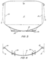
- Figure 5 is a schematic plan view of the sheet to form the tank floor;
- Figure 6 is a schematic sectioned front elevation of one side of the tank of Figure 1;
- Figure 7 is a schematic rear elevation of the tank of Figure 1;
- Figure 8 is a schematic sectioned side elevation of a side wall of the tank of Figure 1;
- Figure 9 is a schematic sectioned end elevation of the side wall of Figure 8; and
- Figure 10 is a schematic plan view of the side wall of Figure 8.
- In the accompanying drawings there is schematically depicted a vessel 10 of a road tanker. The vessel 10 consists of a shell 11 encompassing a
chamber 12 to receive a liquid to be transported. - The forward end of the vessel 10 is provided with a
forward bulkhead 12 which is convex and which has adjacent its extremities ahollow section 13 which acts as a reinforcement in that area which aids in minimising damage to the vessel 10 should the forward corners of the shell 11 receive an impact. Therear bulkhead 14 is concave and extends at its extremities tohollow sections 15 which aid in reinforcing the rear extremities of the vessel 10 to aid it in resisting an impact in that area. The concave configuration of thebulkhead 14 also acts to minimise aerodynamic drag. Since thebulkhead 14 extends to vertically extendingedges 16 it sheds vortices from thesevertical edges 16. - Extending transversely across the chamber are
dividers 17 and/orbaffles 18. Each of thesedividers 17 andbaffles 18 is secured to aside panel 19 viamountings 20. Eachmounting 20 is vertically extending and is of a generally "U-shaped" transverse cross section. - In Figures 3 and 4 there is schematically depicted one of the
dividers 17. - The shell 11 consists of the
side panels 19, afloor panel 21 and aroof panel 22. - Each
side panel 19 consists of asheet 23 joined at its upper end to ahollow section 24 which reinforces the upper edges of the tank 10 to again aid in strengthening the tank 10 against impact, particularly impact resulting from a rollover. Theside panel 19 extends to anupper sheet 25 of theroof panel 22 whichupper sheet 25 is also provided with ahollow section 26 again designed to aid in strengthening the tank 10 against an impact which may result from a rollover. - The
sheet 23 is deformed adjacent its lower portions so as to follow the contour 27 at the forward end of the tank 10, and to follow thecontour 28 adjacent the rear of the tank 10. The mean profile is illustrated by thecontour 29. Thecontours - The
floor panel 21 is formed from a flat sheet. Thepanel 21 is cut to provide transversely extendingslots 30 which are generally arcuate. In Figure 5, thefloor panel 21 is illustrated in its flat form prior to being deformed to its curved configuration in the formed vessel 10. Thefloor panel 21 is also provided withfurther slots 31 which also extend generally transverse of thelongitudinal axis 32 of thefloor panel 21. As best seen in Figure 5, theslots longitudinal axis 32. - Each of the
side panels 19 is provided with a plurality of themountings 20. Each of thedividers 17 and/orbaffles 18 are welded to associated transversely alignedmountings 20. - Each of the
dividers 17 and/or baffles 18 are provided with downwardly projecting pairs offlanges 33 which are intended to project through the pairs ofslots flanges 33 provide mountings for wheel assemblies and other apparatus to be secured to the vessel 10. In Figures 3 and 4, theflanges 33 are illustrated as receivingadaptors 34 to adapt theflanges 34 to provide mountings for the wheel assemblies. - The above described tank is of an aluminium construction. In manufacturing the tank 10, the
floor panel 21 is first welded to thepre-assembled side panels 19. Thereafter, thefloor panel 21 is supported so as to assume its intended configuration. Thereafter, thedividers 17 and/or baffles 18 are placed in position so as to extend downwardly through their associatedslots flanges 33 then project through thefloor panel 21. While thedividers 17 and/or baffles 18 are held in position, theside panels 19 are pivotted upwardly to a position where themountings 20 abut their associateddivider 17 and/orbaffle 18. While this process is taking place, thepanels roof panel 22 may be added or alternatively folded in position with theside panels 19. This operation may be conveniently performed by placing the unformed shell 11 in a sling. - It should be appreciated that the
floor panel 21 is shaped to provide the tank 10 with an increasing transverse cross section toward the rear of the tank 10. This is achieved by having thefloor panel 21, in its finishied profile, conforming generally to portions of three frusto-conical surfaces. The central portion of thefloor panel 21 conforms basically to a frusto-conical surface which tapers rearwardly. The side portions of thepanel 21 conform to frusto-conical surfaces which taper forwardly. By having the various portions of thefloor 21 conform to various frusto-conical surfaces, thepanel 21 can be deformed without buckling since it will bend about generally straight lines extending longitudinally of thepanel 21.
characterised by
flanges downwardly projecting from said walls, and projecting through transversely extending slots formed in said floor portion of said shell said flanges providing mounting means externally of said shell at longitudinally spaced locations along the shell.
prior to locating said walls with respect to said floor portion, said floor portion is provided with a plurality of transversely extending slots to receive downwardly projecting flanges provided on said walls;
said step of locating said walls with respect of said floor portion comprises placing said walls on said floor portion so that said flanges locate in said slots;
said step of deforming said sheet causes said flanges to project through said slots thereby to provide external mountings at longitudinally spaced locations along the tank.
Claims (10)
- A tank (10) to transport liquid, said tank (10) comprising:an elongated shell (11) enclosing an elongated chamber (12) to receive the liquid;a plurality of walls (17,18) extending transversely of said chamber (12) at longitudinally spaced locations along the chamber (12)wherein each said wall (17,18) comprises a peripheral edge portion abutting an internal surface of a floor portion of said shell, said floor portion (21) of said shell being curved to conform to the profile of said wall (17,18)
characterised in that
each said wall (17,18) further comprises downwardly projecting flanges, projecting through transversely aligned transversely extending slots (30,31) formed in said floor portion (21) of said shell (11) said flanges (33) providing mounting means externally of said shell (11) at longitudinally spaced locations along the shell (11). - The tank (10) of claim 1, wherein said slots (30) are arranged in pairs which are aligned transversely of the chamber (12), with each pair of slots (30, 31) being associated with a respective one of the walls (17, 18) and each wall (17, 18) has a pair of said flanges (33) which project into an associated pair of the slots (30, 31).
- The tank (10) of claim 1 or 2, wherein the transverse cross-sectional area of said chamber (12) increases from a forward end of said tank (10), to a rear end of said tank (10).
- The tank (10) of any preceding claim wherein a central section of said floor portion (21) generally conforms to a frusto-conical surface extending longitudinally of the tank (10) and having its longitudinal axis aligned longitudinally of the tank (10).
- The tank (10) of claim 4 wherein the frusto-conical surface of said central section tapers away from said or a forward end.
- The tank (10) of claim 5 wherein side sections of said floor portion (21) generally each conform to a frusto-conical surface extending longitudinally of the tank (10) and having its longitudinal axis aligned longitudinally of the tank wherein said frusto-conical surfaces of said side sections of said floor portion taper towards said foreward end.
- A method of manufacturing a tank (10) to transport liquids, said method comprising the steps of:providing a sheet of aluminium material with a central elongated portion thereof being adapted to provide a floor portion (21) of the tank (10);providing a plurality of walls (17,18) to be located internally of said tank (10);locating said walls with respect to said floor portion (21) so that said walls (17,18) are transversely arranged and longitudinally spaced;deforming said sheet by pulling it around the peripheral edges of the walls (17,18) so as to conform to the profile thereof;securing said sheet to said walls (17, 18);characterised in that
prior to locating said walls (17,18) with respect to said floor portion (21), said floor portion (21) is provided with a plurality of transversely extending slots (30,31) to receive downwardly projecting flanges (30) provided on said walls;
said step of locating said walls with respect of said floor portion comprises placing said walls (17,18) on said floor portion (21) so that said flanges (33) locate in said slots (30,31);
said step of deforming said sheet causes said flanges (33) to project through said slots (30,31) thereby to provide external mountings at longitudinally spaced locations along the tank (10). - The method of claim 7, wherein said walls (17,18) are selected such that when said sheet is deformed by pulling it around the peripheral edges of the walls (17,18) said sheet deforms by bending about straight lines extending longitudinally of the tank (10).
- The method of claim 8, wherein said straight lines follow frusto-conical surfaces, which frusto-conical surfaces have their longitudinal axes extending longitudinally of the tank (10).
- The tank of any one of claims 1 to 6, wherein said tank further comprises a wheel assembly supporting said shell (12) via said flanges (13), wherein the flanges (13) provide mountings for said wheel assembly.
Priority Applications (1)
| Application Number | Priority Date | Filing Date | Title |
|---|---|---|---|
| EP95119873A EP0720932B1 (en) | 1991-04-04 | 1992-04-03 | Road tanker |
Applications Claiming Priority (2)
| Application Number | Priority Date | Filing Date | Title |
|---|---|---|---|
| AU5434/91 | 1991-04-04 | ||
| AUPK543491 | 1991-04-04 |
Related Child Applications (2)
| Application Number | Title | Priority Date | Filing Date |
|---|---|---|---|
| EP95119873.8 Division-Into | 1992-04-03 | ||
| EP95119873A Division EP0720932B1 (en) | 1991-04-04 | 1992-04-03 | Road tanker |
Publications (3)
| Publication Number | Publication Date |
|---|---|
| EP0507612A2 EP0507612A2 (en) | 1992-10-07 |
| EP0507612A3 EP0507612A3 (en) | 1992-12-16 |
| EP0507612B1 true EP0507612B1 (en) | 1997-01-29 |
Family
ID=3775314
Family Applications (2)
| Application Number | Title | Priority Date | Filing Date |
|---|---|---|---|
| EP95119873A Expired - Lifetime EP0720932B1 (en) | 1991-04-04 | 1992-04-03 | Road tanker |
| EP92302970A Expired - Lifetime EP0507612B1 (en) | 1991-04-04 | 1992-04-03 | Road tanker |
Family Applications Before (1)
| Application Number | Title | Priority Date | Filing Date |
|---|---|---|---|
| EP95119873A Expired - Lifetime EP0720932B1 (en) | 1991-04-04 | 1992-04-03 | Road tanker |
Country Status (5)
| Country | Link |
|---|---|
| EP (2) | EP0720932B1 (en) |
| JP (1) | JP3387521B2 (en) |
| AT (2) | ATE194107T1 (en) |
| DE (2) | DE69217101D1 (en) |
| ZA (1) | ZA922481B (en) |
Families Citing this family (3)
| Publication number | Priority date | Publication date | Assignee | Title |
|---|---|---|---|---|
| FR2797236B1 (en) | 1999-08-02 | 2002-01-25 | Ets Magyar | TANK FOR THE TRANSPORT OF LIQUIDS, IN PARTICULAR INSULATED SEMI-TRAILER TANK |
| CN103979231B (en) * | 2014-05-29 | 2016-08-24 | 南通航海机械集团有限公司 | Aerial kerosene refueling terminal oil storage tank |
| CN104495130A (en) * | 2014-12-22 | 2015-04-08 | 山东交通学院 | A liquid tank truck preventing liquid from sloshing |
Family Cites Families (3)
| Publication number | Priority date | Publication date | Assignee | Title |
|---|---|---|---|---|
| US2091731A (en) * | 1934-04-30 | 1937-08-31 | Standard Steel Works | Tank |
| US3131949A (en) * | 1960-04-28 | 1964-05-05 | Pullman Inc | Self-sustaining transportation tank |
| GB1527799A (en) * | 1977-05-10 | 1978-10-11 | Clarke Chapman Ltd | Tanks |
-
1992
- 1992-04-03 DE DE69217101T patent/DE69217101D1/en not_active Expired - Lifetime
- 1992-04-03 EP EP95119873A patent/EP0720932B1/en not_active Expired - Lifetime
- 1992-04-03 ZA ZA922481A patent/ZA922481B/en unknown
- 1992-04-03 JP JP10911492A patent/JP3387521B2/en not_active Expired - Fee Related
- 1992-04-03 EP EP92302970A patent/EP0507612B1/en not_active Expired - Lifetime
- 1992-04-03 AT AT95119873T patent/ATE194107T1/en not_active IP Right Cessation
- 1992-04-03 DE DE69231209T patent/DE69231209D1/en not_active Expired - Lifetime
- 1992-04-03 AT AT92302970T patent/ATE148400T1/en not_active IP Right Cessation
Also Published As
| Publication number | Publication date |
|---|---|
| ATE194107T1 (en) | 2000-07-15 |
| JPH05132091A (en) | 1993-05-28 |
| EP0507612A3 (en) | 1992-12-16 |
| EP0720932B1 (en) | 2000-06-28 |
| EP0507612A2 (en) | 1992-10-07 |
| DE69231209D1 (en) | 2000-08-03 |
| ZA922481B (en) | 1993-03-31 |
| EP0720932A2 (en) | 1996-07-10 |
| ATE148400T1 (en) | 1997-02-15 |
| EP0720932A3 (en) | 1997-10-15 |
| DE69217101D1 (en) | 1997-03-13 |
| JP3387521B2 (en) | 2003-03-17 |
Similar Documents
| Publication | Publication Date | Title |
|---|---|---|
| US20220194201A1 (en) | Battery support and protection structure for a vehicle | |
| US5779092A (en) | Baffle system for tank | |
| CA2399523C (en) | Vehicle body rear part structure | |
| US6679523B2 (en) | Sub-frame structure of motor-vehicle | |
| US4357027A (en) | Motor vehicle fuel tank | |
| US7407192B2 (en) | Vehicle end structure | |
| US20060202519A1 (en) | Unitized vehicle rear body structure | |
| CN207257804U (en) | A kind of electronic logistic car container skeleton structure | |
| EP1642810A1 (en) | Automobile underbody structure | |
| US4545172A (en) | Energy absorbing structure | |
| US12415569B2 (en) | Rocker insert with corrugated structure | |
| EP4335729A1 (en) | Vehicle body | |
| JPH0464247B2 (en) | ||
| US20090261620A1 (en) | Energy absorbing system for a vehicle | |
| JPH0610027B2 (en) | Transport tank | |
| EP0720932B1 (en) | Road tanker | |
| GB2167018A (en) | Reinforcing vehicle body structures | |
| US5340177A (en) | Vehicle bumper with step | |
| CN114802481B (en) | Vehicle body structure and vehicle | |
| US5301980A (en) | Road tanker | |
| AU640866B2 (en) | Road tanker | |
| GB2087319A (en) | Support arrangement for the body of a motor vehicle especially a passenger car | |
| EP0683741B1 (en) | Structural sub-assembly | |
| EP3393891B1 (en) | Modular cabin for industrial vehicle comprising an auxiliary frame, an auxiliary frame for such a modular cabin, and a method for producing such a modular cabin. | |
| CN217224257U (en) | Mounting seat splicing device |
Legal Events
| Date | Code | Title | Description |
|---|---|---|---|
| PUAI | Public reference made under article 153(3) epc to a published international application that has entered the european phase |
Free format text: ORIGINAL CODE: 0009012 |
|
| AK | Designated contracting states |
Kind code of ref document: A2 Designated state(s): AT BE CH DE DK ES FR GB GR IT LI LU MC NL PT SE |
|
| PUAL | Search report despatched |
Free format text: ORIGINAL CODE: 0009013 |
|
| AK | Designated contracting states |
Kind code of ref document: A3 Designated state(s): AT BE CH DE DK ES FR GB GR IT LI LU MC NL PT SE |
|
| 17P | Request for examination filed |
Effective date: 19930611 |
|
| 17Q | First examination report despatched |
Effective date: 19941026 |
|
| GRAG | Despatch of communication of intention to grant |
Free format text: ORIGINAL CODE: EPIDOS AGRA |
|
| GRAH | Despatch of communication of intention to grant a patent |
Free format text: ORIGINAL CODE: EPIDOS IGRA |
|
| GRAH | Despatch of communication of intention to grant a patent |
Free format text: ORIGINAL CODE: EPIDOS IGRA |
|
| GRAA | (expected) grant |
Free format text: ORIGINAL CODE: 0009210 |
|
| DX | Miscellaneous (deleted) | ||
| AK | Designated contracting states |
Kind code of ref document: B1 Designated state(s): AT BE CH DE DK ES FR GB GR IT LI LU MC NL PT SE |
|
| PG25 | Lapsed in a contracting state [announced via postgrant information from national office to epo] |
Ref country code: IT Free format text: LAPSE BECAUSE OF FAILURE TO SUBMIT A TRANSLATION OF THE DESCRIPTION OR TO PAY THE FEE WITHIN THE PRE;WARNING: LAPSES OF ITALIAN PATENTS WITH EFFECTIVE DATE BEFORE 2007 MAY HAVE OCCURRED AT ANY TIME BEFORE 2007. THE CORRECT EFFECTIVE DATE MAY BE DIFFERENT FROM THE ONE RECORDED.SCRIBED TIME-LIMIT Effective date: 19970129 Ref country code: DK Effective date: 19970129 Ref country code: ES Free format text: THE PATENT HAS BEEN ANNULLED BY A DECISION OF A NATIONAL AUTHORITY Effective date: 19970129 Ref country code: GR Free format text: LAPSE BECAUSE OF FAILURE TO SUBMIT A TRANSLATION OF THE DESCRIPTION OR TO PAY THE FEE WITHIN THE PRESCRIBED TIME-LIMIT Effective date: 19970129 Ref country code: AT Effective date: 19970129 Ref country code: CH Effective date: 19970129 Ref country code: FR Effective date: 19970129 Ref country code: NL Free format text: LAPSE BECAUSE OF FAILURE TO SUBMIT A TRANSLATION OF THE DESCRIPTION OR TO PAY THE FEE WITHIN THE PRESCRIBED TIME-LIMIT Effective date: 19970129 Ref country code: LI Effective date: 19970129 Ref country code: BE Effective date: 19970129 |
|
| REF | Corresponds to: |
Ref document number: 148400 Country of ref document: AT Date of ref document: 19970215 Kind code of ref document: T |
|
| REG | Reference to a national code |
Ref country code: CH Ref legal event code: EP |
|
| REF | Corresponds to: |
Ref document number: 69217101 Country of ref document: DE Date of ref document: 19970313 |
|
| PG25 | Lapsed in a contracting state [announced via postgrant information from national office to epo] |
Ref country code: PT Effective date: 19970429 Ref country code: SE Effective date: 19970429 |
|
| PG25 | Lapsed in a contracting state [announced via postgrant information from national office to epo] |
Ref country code: LU Free format text: LAPSE BECAUSE OF NON-PAYMENT OF DUE FEES Effective date: 19970430 Ref country code: DE Effective date: 19970430 |
|
| EN | Fr: translation not filed | ||
| NLV1 | Nl: lapsed or annulled due to failure to fulfill the requirements of art. 29p and 29m of the patents act | ||
| REG | Reference to a national code |
Ref country code: CH Ref legal event code: PL |
|
| PG25 | Lapsed in a contracting state [announced via postgrant information from national office to epo] |
Ref country code: MC Effective date: 19971031 |
|
| PLBE | No opposition filed within time limit |
Free format text: ORIGINAL CODE: 0009261 |
|
| STAA | Information on the status of an ep patent application or granted ep patent |
Free format text: STATUS: NO OPPOSITION FILED WITHIN TIME LIMIT |
|
| 26N | No opposition filed | ||
| REG | Reference to a national code |
Ref country code: GB Ref legal event code: IF02 |
|
| REG | Reference to a national code |
Ref country code: GB Ref legal event code: 732E |
|
| PGFP | Annual fee paid to national office [announced via postgrant information from national office to epo] |
Ref country code: GB Payment date: 20050330 Year of fee payment: 14 |
|
| PG25 | Lapsed in a contracting state [announced via postgrant information from national office to epo] |
Ref country code: GB Free format text: LAPSE BECAUSE OF NON-PAYMENT OF DUE FEES Effective date: 20060403 |
|
| GBPC | Gb: european patent ceased through non-payment of renewal fee |
Effective date: 20060403 |