EP0507069B1 - Mechanical device, particularly for the movement and selective locking of a chair - Google Patents
Mechanical device, particularly for the movement and selective locking of a chair Download PDFInfo
- Publication number
- EP0507069B1 EP0507069B1 EP92103070A EP92103070A EP0507069B1 EP 0507069 B1 EP0507069 B1 EP 0507069B1 EP 92103070 A EP92103070 A EP 92103070A EP 92103070 A EP92103070 A EP 92103070A EP 0507069 B1 EP0507069 B1 EP 0507069B1
- Authority
- EP
- European Patent Office
- Prior art keywords
- shaft
- chair
- pin
- boxlike element
- boxlike
- Prior art date
- Legal status (The legal status is an assumption and is not a legal conclusion. Google has not performed a legal analysis and makes no representation as to the accuracy of the status listed.)
- Expired - Lifetime
Links
Images


Classifications
-
- A—HUMAN NECESSITIES
- A47—FURNITURE; DOMESTIC ARTICLES OR APPLIANCES; COFFEE MILLS; SPICE MILLS; SUCTION CLEANERS IN GENERAL
- A47C—CHAIRS; SOFAS; BEDS
- A47C7/00—Parts, details, or accessories of chairs or stools
- A47C7/36—Supports for the head or the back
- A47C7/40—Supports for the head or the back for the back
- A47C7/44—Supports for the head or the back for the back with elastically-mounted frame
- A47C7/443—Supports for the head or the back for the back with elastically-mounted frame with coil springs
-
- A—HUMAN NECESSITIES
- A47—FURNITURE; DOMESTIC ARTICLES OR APPLIANCES; COFFEE MILLS; SPICE MILLS; SUCTION CLEANERS IN GENERAL
- A47C—CHAIRS; SOFAS; BEDS
- A47C3/00—Chairs characterised by structural features; Chairs or stools with rotatable or vertically-adjustable seats
- A47C3/02—Rocking chairs
- A47C3/025—Rocking chairs with seat, or seat and back-rest unit, elastically mounted in a rigid frame
- A47C3/026—Rocking chairs with seat, or seat and back-rest unit, elastically mounted in a rigid frame with a central column, e.g. rocking office chairs; Tilting chairs
-
- A—HUMAN NECESSITIES
- A47—FURNITURE; DOMESTIC ARTICLES OR APPLIANCES; COFFEE MILLS; SPICE MILLS; SUCTION CLEANERS IN GENERAL
- A47C—CHAIRS; SOFAS; BEDS
- A47C7/00—Parts, details, or accessories of chairs or stools
- A47C7/36—Supports for the head or the back
- A47C7/40—Supports for the head or the back for the back
- A47C7/44—Supports for the head or the back for the back with elastically-mounted frame
- A47C7/441—Supports for the head or the back for the back with elastically-mounted frame with adjustable elasticity
Definitions
- the present invention relates to a mechanical device particularly for the movement and the selective locking of a chair.
- One well-known type consists of a chair whose seat is fixed with regard to the column projecting from a swivel base, with the possibility of tilting the back in relation to the seat.
- EP-A-0,392,984 is a mechanical device, particularly for the movement and the selective locking of a chair as defined in the preamble of claim 1.
- this known device has two levers for the control of the chair, which requires a certain dexterity on the part of a user.
- FR-A-2,075,176 is a single-lever device for the movement and the selective locking of a chair, however, this known device is structurally complex and expensive to manufacture.
- the main aim of the present invention is therefore to eliminate the above-mentioned drawbacks in well-known types by devising a mechanical device that, once it has been attached to a chair will make it possible to attain an optimal adjustment in the positioning of said chair by performing operations that are quick and easy for the user.
- Another important object is to provide a mechanical device that will make it possible for the user to obtain these adjustments selectively and, therefore, according to specific requirements.
- Yet another important object is to provide a device which is structurally simple and easy to manufacture.
- a further object of the invention is to provide a mechanical device which will prove reliable and safe to use, with rather limited costs that will increase its application even on chairs whose overall value is not high.
- the mechanical device identified by reference sign 1, proves particularly usable for the movement and selective blocking of a chair 2 attachable at the upper part to a pair of arms 3a and 3b integrally connected transversely and at one end to a pivoting pin 4.
- a first boxlike element 5 is attached in a swivel fashion to said pivoting pin 4 proximate to the ends integral with the pair of arms 3a and 3b.
- connection between both pairs of sleeves may be made by gluing them or by means of a recess or other equivalent solution.
- These last items are preferably made of self-lubricating plastic material, such as nylon, and can be closed up between each other by means of the first and second screws in order to allow the swivel connection to the pivoting pin 4 of the boxlike element 5.
- a U-channel 11 can be temporarily associated at the back with the two pairs of sleeves in order to conceal them.
- the boxlike element has in connection with its vertex a conical bushing 13, fitted for receiving the end of a column 14, provided with a control 15 for the gas supply.
- the boxlike element 5 has laterally a second hole 16a and, in connection with a preformed tab 16b, projecting internally, a third hole 16c, these second and third holes having the same axis transversal to the boxlike element 5 in relation to them, which can be positioned, and with the end 17 of an accessible shaft 18 passing through to the other end to the user.
- box-shaped lever or molding box 20 with an essentially trapezoidal shape, whose larger end 21 is linked to the pivoting pin 4, that can be associated with said boxlike element 5.
- This molding box 20 has a longitudinal extension lower than that of the boxlike element 5, which extension is provided laterally with a third appendage 22 which extends beyond the smaller end 23.
- This third appendage 22 is located in the interspace between the planes in which the tab 16b and the adjacent lateral surface of the boxlike element lie.
- the shaft 18 is a means which is able to permit the selective locking of the position of the chair with regard to the boxlike element and which is for operating the gas control.
- the use of the mechanical device 1 is as follows: once the user has seated himself on the chair, he may easily modify its disposition, predetermining both its height above the floor and its tilt, doing so by merely acting on the single shaft 18, which projects laterally from the mechanical device 1.
- the action of the user on said shaft 18 may be divided into two phases, depending on whether he wants to act on the locking or the activation of the tilt or on the gas-piston control.
- the user may remain seated in a relaxed position since the chair is slightly inclined backwards.
- the user wants to operate the gas-piston control 15, he should grasp the end fin 29 of the shaft 18 pulling it upward: by so doing, the second appendage 19 squeezes the aforesaid control 15 activating the gas supply and thereby varying the height position of the chair.
Landscapes
- Chairs Characterized By Structure (AREA)
- Chairs For Special Purposes, Such As Reclining Chairs (AREA)
- Lock And Its Accessories (AREA)
- Chair Legs, Seat Parts, And Backrests (AREA)
- Supporting Of Heads In Record-Carrier Devices (AREA)
- Load-Engaging Elements For Cranes (AREA)
- Seats For Vehicles (AREA)
- Handcart (AREA)
- Special Chairs (AREA)
Abstract
Description
- The present invention relates to a mechanical device particularly for the movement and the selective locking of a chair.
- Currently there are well-known mechanical devices, which are used to adjust the tilt of a chair.
- One well-known type consists of a chair whose seat is fixed with regard to the column projecting from a swivel base, with the possibility of tilting the back in relation to the seat.
- This type, however, presents an annoying drawback whenever the user shifts his position on the seat as a result of the natural stretching of the user's body.
- As a partial solution to this drawback, it is common to make a seat and back connected to each other so that a tilt of the back is accompanied by a shift or tilt of the seat: therefore, below the seat there is usually a first lever used to control a gas piston that lifts the seat to a greater or lesser degree and another lever used to operate a mechanism installed for tilting to a greater or lesser degree.
- This well-known type presents some drawbacks: the use of two levers forces the user to seek specifically the one he wants with the result that many times the wrong control is used requiring the user to go back to the former condition.
- Furthermore, a certain amount of dexterity is required from the user who must seek out the two levers without being able to see them.
- Lastly, the mechanisms that interact with the two levers are of necessity complex and therefore their construction is expensive.
- Known from EP-A-0,392,984 is a mechanical device, particularly for the movement and the selective locking of a chair as defined in the preamble of claim 1. However, this known device has two levers for the control of the chair, which requires a certain dexterity on the part of a user.
- Also known from FR-A-2,075,176 is a single-lever device for the movement and the selective locking of a chair, however, this known device is structurally complex and expensive to manufacture.
- The main aim of the present invention is therefore to eliminate the above-mentioned drawbacks in well-known types by devising a mechanical device that, once it has been attached to a chair will make it possible to attain an optimal adjustment in the positioning of said chair by performing operations that are quick and easy for the user.
- Within the scope of the above-mentioned aim, another important object is to provide a mechanical device that will make it possible for the user to obtain these adjustments selectively and, therefore, according to specific requirements.
- Yet another important object is to provide a device which is structurally simple and easy to manufacture.
- A further object of the invention is to provide a mechanical device which will prove reliable and safe to use, with rather limited costs that will increase its application even on chairs whose overall value is not high.
- The above-mentioned aim and objects, as well as others which will become apparent hereinafter, are achieved by a mechanical device, particularly for the movement and selective locking of a chair, as defined in the independent claim 1.
- Various embodiment of the device according to claim 1 are defined in the
dependent claims 2 to 8. - Further characteristics and advantages of the invention will become apparent from the detailed description of a particular but not exclusive embodiment, illustrated only by way of non-limitative example in the accompanying drawings wherein:
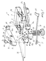
- Figure 1 shows the device in an exploded view;
- Figure 2 shows the device in a three-quarter partially cross-sectional view;
- Figure 3 shows the device in the non-tilting condition for the chair if the
shaft 18 is inserted in thethird hole 16c made on thetab 16b; - Figure 4 shows the device in the condition of possible tilting for the chair if the
shaft 18 is withdrawn from thethird hole 16c. - With reference to the above figures, the mechanical device, identified by reference sign 1, proves particularly usable for the movement and selective blocking of a
chair 2 attachable at the upper part to a pair of arms 3a and 3b integrally connected transversely and at one end to a pivotingpin 4. - A first boxlike element 5 is attached in a swivel fashion to said pivoting
pin 4 proximate to the ends integral with the pair of arms 3a and 3b. - From this boxlike element which, when viewed from above, has a triangular shape, there project laterally a pair of
first appendages 6a and 6b equipped with preformed first holes 7a and 7b for the fastening by means of the first and second screws, indicated by thereference numerals 8a and 8b respectively, and two pairs ofsleeves - Alternatively, the connection between both pairs of sleeves may be made by gluing them or by means of a recess or other equivalent solution.
- These last items are preferably made of self-lubricating plastic material, such as nylon, and can be closed up between each other by means of the first and second screws in order to allow the swivel connection to the pivoting
pin 4 of the boxlike element 5. - Advantageously, a
U-channel 11, can be temporarily associated at the back with the two pairs of sleeves in order to conceal them. - The boxlike element has in connection with its vertex a
conical bushing 13, fitted for receiving the end of acolumn 14, provided with acontrol 15 for the gas supply. - The boxlike element 5 has laterally a
second hole 16a and, in connection with apreformed tab 16b, projecting internally, athird hole 16c, these second and third holes having the same axis transversal to the boxlike element 5 in relation to them, which can be positioned, and with theend 17 of anaccessible shaft 18 passing through to the other end to the user. - In the interspace between the second holes there projects, from the
end 17 of theshaft 18, asecond appendix 19 able to interact, by turning the shaft, with thecontrol 15 for the gas supply. - Furthermore, there is a box-shaped lever or
molding box 20, with an essentially trapezoidal shape, whoselarger end 21 is linked to the pivotingpin 4, that can be associated with said boxlike element 5. - This
molding box 20 has a longitudinal extension lower than that of the boxlike element 5, which extension is provided laterally with athird appendage 22 which extends beyond thesmaller end 23. - This
third appendage 22 is located in the interspace between the planes in which thetab 16b and the adjacent lateral surface of the boxlike element lie. - Below the
molding box 20 there are means of resilient opposition comprising asmall pin 24, around which there is aspring 25 to which it is associated and aknob 26 at one end, which passes through themolding box 20 and the boxlike element 5 at the fourth and fifth holes made therein and indicated by thereference numerals - The
shaft 18 is a means which is able to permit the selective locking of the position of the chair with regard to the boxlike element and which is for operating the gas control. - The use of the mechanical device 1 is as follows: once the user has seated himself on the chair, he may easily modify its disposition, predetermining both its height above the floor and its tilt, doing so by merely acting on the
single shaft 18, which projects laterally from the mechanical device 1. - Advantageously, the action of the user on said
shaft 18 may be divided into two phases, depending on whether he wants to act on the locking or the activation of the tilt or on the gas-piston control. - Starting with the condition shown in figure 2, wherein the
shaft 18 engages both thesecond hole 16a and thethird hole 16c and thethird appendage 22 of themolding box 20 presses against the far end of theshaft 18 from below, the chair is permitted to tilt against thespring 25. - Grasping the
shaft 18 and pulling outward, the user can withdraw said shaft and free its far end from thethird hole 16c; by so doing, the condition of free tilting is obtained for the chair. - If the user reinserts the end of the
shaft 18 in thethird hole 16c, two different situations can be obtained: if thethird appendage 22 is lodged between the upper surface of themolding box 20 and the end of theshaft 18, as illustrated in figure 3, the user may remain seated in a working position since it is not possible for the chair to revolve around the pin. - If, instead, the end of the
shaft 18 is lodged between the upper surface of themolding box 20 and thethird appendage 22, as illustrated in figure 4, the user may remain seated in a relaxed position since the chair is slightly inclined backwards. - If, instead, the user wants to operate the gas-
piston control 15, he should grasp theend fin 29 of theshaft 18 pulling it upward: by so doing, thesecond appendage 19 squeezes theaforesaid control 15 activating the gas supply and thereby varying the height position of the chair. - These operations may, furthermore, be done "blindly", in view of the extreme operating simplicity and the accessibility of the shaft which, since there is only one, is easy for the user to locate.
- It is thus observed how the invention achieves the above-mentioned aim and objects, there being provided a mechanical device that makes it possible to achieve an optimal positioning of the chair by means of directly acting on the only locking means, consisting of the
shaft 18 which interacts with themolding box 20. - Where technical features mentioned in any claim are followed by reference signs, those reference signs have been included for the sole purpose of increasing the intelligibility of the claims and accordingly, such reference signs do not have any limiting effect on the scope of each element identified by way of example by such reference signs.
Claims (8)
- Mechanical device (1), particularly for the movement and the selective locking of a chair, comprising a pair of arms (3a,3b) to be fastened to said chair, a boxlike element (5), attached in a swiveling fashion to a pivoting pin (4) integral with said pair of arms (3a,3b), and a lever (20), integral with said pin (4) and interacting through resilient means (24,25) with said boxlike element (5), characterized in that the device comprises a shaft (18) for the selective locking of the position of said chair with regard to said boxlike element (5) and for the control of a gas piston, a pair of first appendages (6a, 6b) projecting laterally from said boxlike element (5), and sleeves (9a, 9b, 10a, 10b) connected to said appendages (6a, 6b) for swivelling connection of said boxlike element (5) to said pin (4).
- Device according to claim 1, characterized in that said boxlike element (5), comprising with regard to its vertex a conical bushing (13) fashioned to receive the end of a column (14) provided with a control (15) for the gas supply, has laterally a second hole (16a) and, in relation to a predisposed tab (16b) projecting internally, a third hole (16c), said second and third holes (16a,16c) having the same axis transversal to said boxlike element (5); with regard to said holes (16a,16c), there is the end (17) of said shaft (18) which can be positioned and passes therethrough, which shaft (18) is accessible at the other end by the user.
- Device according to claim 2, characterized in that in an interspace between said second and third holes (16a,16c), there projects from said end (17) of said shaft (18) a second appendage (19) designed to interact, when said shaft (18) is turned, with said control (15) for the gas supply.
- Device according to claim 3, characterized in that said lever (20) has an essentially trapezoidal shape defining a smaller end (23) and a larger end (21), said larger end (21) being linked to said pivoting pin (4), said lever (20) extending longitudinally below said boxlike element (5) and presenting laterally a third appendage (22) which extends beyond said smaller end (23).
- Device according to claims 2 and 4, characterized in that said third appendage (22) is positioned in an interspace defined between the planes in which lie said tab (16b) and the adjacent lateral surface of said boxlike element (5).
- Device according to claim 1, characterized in that said resilient means (24, 25) are located below said lever (20) and comprise a small pin (24), a spring (25) extending around said pin (24), and a knob (26) located at one end of said pin (24), said pin (24) passing through said lever (20) and said boxlike element (5) in fourth (27) and fifth (28) holes provided therein.
- Device according to one or more of the preceding claims, characterized in that the end (17) of said shaft (18) inside said boxlike element (5) is insertable in said third hole (16c) for positioning said third appendage (22) above or below the shaft (18), said shaft (18) permitting tilting of said chair upon withdrawal of said end (17) from said third hole (16c).
- Device according to one or more of the preceding claims, characterized in that it comprises a U-channel (11) temporarily rearwardly connectable to said two pairs of sleeves (9a,9b,10a,10b) to conceal them.
Applications Claiming Priority (2)
| Application Number | Priority Date | Filing Date | Title |
|---|---|---|---|
| ITTV910028 | 1991-03-01 | ||
| ITTV910028A IT1247369B (en) | 1991-03-01 | 1991-03-01 | MECHANICAL DEVICE, PARTICULARLY FOR HANDLING AND SELECTIVE LOCKING OF A SESSION |
Publications (2)
| Publication Number | Publication Date |
|---|---|
| EP0507069A1 EP0507069A1 (en) | 1992-10-07 |
| EP0507069B1 true EP0507069B1 (en) | 1996-02-14 |
Family
ID=11418821
Family Applications (1)
| Application Number | Title | Priority Date | Filing Date |
|---|---|---|---|
| EP92103070A Expired - Lifetime EP0507069B1 (en) | 1991-03-01 | 1992-02-24 | Mechanical device, particularly for the movement and selective locking of a chair |
Country Status (9)
| Country | Link |
|---|---|
| US (1) | US5280998A (en) |
| EP (1) | EP0507069B1 (en) |
| AT (1) | ATE134113T1 (en) |
| BR (1) | BR9200694A (en) |
| CA (1) | CA2061615C (en) |
| DE (1) | DE69208275T2 (en) |
| ES (1) | ES2083003T3 (en) |
| IT (1) | IT1247369B (en) |
| MX (1) | MX9200832A (en) |
Families Citing this family (15)
| Publication number | Priority date | Publication date | Assignee | Title |
|---|---|---|---|---|
| US5630648A (en) * | 1992-08-27 | 1997-05-20 | Harry C. Sweere | Dynamic posture chair |
| US5427434A (en) * | 1993-07-30 | 1995-06-27 | Leggett & Platt, Incorporated | Chair tilt and height adjustment mechanism |
| US5572201A (en) * | 1994-08-05 | 1996-11-05 | Federal Signal Corporation | Alerting device and system for abnormal situations |
| WO2000013551A1 (en) * | 1998-09-03 | 2000-03-16 | Mh Stålmøbler A/S | Tilting device for a seat |
| DE19849522A1 (en) * | 1998-10-21 | 2000-04-27 | Drabert Gmbh | Office chair with a seat tilt adjustment |
| US6290296B1 (en) * | 1999-07-01 | 2001-09-18 | Northfield Metal Products Limited | Anti-rattle pad |
| US6131998A (en) * | 1999-11-22 | 2000-10-17 | Su; Tung-Hua | Chassis for a chair seat |
| US6598936B1 (en) | 2001-04-11 | 2003-07-29 | Michael N. Klein | Multi-task mid-pivot chair control mechanism |
| ITTV20030021A1 (en) * | 2003-02-12 | 2004-08-13 | O M S Spa | MECHANICAL DEVICE, IN PARTICULAR FOR THE HANDLING OF THE SEAT AND BACK OF A SEAT. |
| US6692077B1 (en) * | 2003-03-27 | 2004-02-17 | Leggett & Platt Ltd. | Height adjustment chair control |
| US20050001132A1 (en) * | 2003-06-13 | 2005-01-06 | Machael Jay R. | Height adjustment cylinder with non-tapered threaded region |
| US7478880B2 (en) | 2005-03-08 | 2009-01-20 | L&P Property Management Company | Multi-purpose adjustment chair mechanism |
| US20100180969A1 (en) * | 2009-01-20 | 2010-07-22 | Jong-Jyr Kau | Elevational adjustment device |
| ES2595530B1 (en) * | 2016-08-10 | 2017-07-17 | Javier PERALES BOTÍA | NEW ERGONOMIC WORK STATION WITH MOVEMENT ASSISTANCE FOR HAIRDRESSERS |
| US11864661B2 (en) | 2021-05-05 | 2024-01-09 | Steelcase Inc | Body support assembly and methods for the use and assembly thereof |
Family Cites Families (31)
| Publication number | Priority date | Publication date | Assignee | Title |
|---|---|---|---|---|
| US555029A (en) * | 1896-02-18 | Chusetts | ||
| US2249828A (en) * | 1938-08-26 | 1941-07-22 | Bassick Co | Posture chair iron |
| GB815779A (en) * | 1957-03-21 | 1959-07-01 | Finn Lie | Tilting mechanism for seat furniture |
| CA737268A (en) * | 1961-07-25 | 1966-06-28 | Lie Finn | Tilting chair construction |
| US3480249A (en) * | 1967-12-11 | 1969-11-25 | Finn Lie | Tilting chair construction |
| US3592433A (en) * | 1969-02-25 | 1971-07-13 | Bliss & Laughlin Ind | Torsion bar chair control |
| FR2075176A5 (en) * | 1970-01-31 | 1971-10-08 | Suspa Federungstech | |
| US3659819A (en) * | 1970-06-08 | 1972-05-02 | Steelcase Inc | Chair iron |
| US3669398A (en) * | 1970-07-23 | 1972-06-13 | Lear Siegler Inc | Adjustable seat supporting assembly |
| US3813073A (en) * | 1972-04-21 | 1974-05-28 | Steelcase Inc | Dual torsion bar chair control |
| GB1425363A (en) * | 1972-05-31 | 1976-02-18 | Lie F | Resilient mounting assembly for a tilting chair |
| NO140961C (en) * | 1976-08-03 | 1979-12-19 | Ivar Kalvatn | INSTALLATION OF CHAIR FOR USE IN BOATS OR VEHICLES |
| DE2748680A1 (en) * | 1977-10-29 | 1979-05-10 | Stoll Kg Christof | INCLINATION DEVICE FOR FURNITURE |
| CA1109386A (en) * | 1978-03-29 | 1981-09-22 | Eddie A.J. Large | Resilient mounting for a reclining seat |
| DE8133573U1 (en) * | 1981-11-17 | 1983-05-05 | Fritz Bauer + Söhne oHG, 8503 Altdorf | LOCKABLE LOCKING DEVICE FOR SEAT PARTS OF SEAT FURNITURE |
| US4431157A (en) * | 1981-11-18 | 1984-02-14 | Tor Arild | Pivotal adjustment mechanism |
| CH659179A5 (en) * | 1983-05-06 | 1987-01-15 | Provenda Marketing Ag | Working chair, especially an office chair |
| US4575151A (en) * | 1983-09-13 | 1986-03-11 | Maridyne, Inc. | Chair tilting mechanism |
| JPS60117742U (en) * | 1984-01-18 | 1985-08-09 | 株式会社岡村製作所 | chair recliner |
| EP0198056B1 (en) * | 1984-10-25 | 1991-01-09 | Konrad Neumüller | Seat support for chairs, especially for rotating work-chairs |
| US4744600A (en) * | 1986-05-06 | 1988-05-17 | Itoki Co., Ltd. | Cushioning mechanism for use with seat of chair and interlocking cushioning mechanism for seat and backrest |
| DE3617539C1 (en) * | 1986-05-24 | 1987-07-23 | Grammer Sitzsysteme Gmbh | Seat with adjustable seat plate and reclining backrest |
| CH670363A5 (en) * | 1986-09-24 | 1989-06-15 | Giroflex Entwicklungs Ag | |
| AT386517B (en) * | 1987-02-10 | 1988-09-12 | Zuend & Co Ag K | CHAIR, IN PARTICULAR WORK CHAIR |
| US4718726A (en) * | 1987-07-07 | 1988-01-12 | Estkowski Michael H | Chair seat tilt control |
| DE3724605C2 (en) * | 1987-07-24 | 1994-02-03 | Inaba Seisakusho Ltd | Seating |
| JPH0520199Y2 (en) * | 1988-11-30 | 1993-05-26 | ||
| IT217532Z2 (en) * | 1989-04-13 | 1991-12-16 | Cofemo Spa | SWINGING GROUP FOR CHAIRS. |
| US4892354A (en) * | 1989-06-30 | 1990-01-09 | Shepherd Products U.S., Inc. | Chair seat tilt control |
| US5029940A (en) * | 1990-01-16 | 1991-07-09 | Westinghouse Electric Corporation | Chair tilt and chair height control apparatus |
| US5018787A (en) * | 1990-06-20 | 1991-05-28 | Shepherd Products U.S. Inc. | Chair seat tilt control |
-
1991
- 1991-03-01 IT ITTV910028A patent/IT1247369B/en active IP Right Grant
-
1992
- 1992-02-20 CA CA002061615A patent/CA2061615C/en not_active Expired - Fee Related
- 1992-02-24 EP EP92103070A patent/EP0507069B1/en not_active Expired - Lifetime
- 1992-02-24 DE DE69208275T patent/DE69208275T2/en not_active Expired - Fee Related
- 1992-02-24 AT AT92103070T patent/ATE134113T1/en not_active IP Right Cessation
- 1992-02-24 ES ES92103070T patent/ES2083003T3/en not_active Expired - Lifetime
- 1992-02-27 MX MX9200832A patent/MX9200832A/en not_active IP Right Cessation
- 1992-02-27 US US07/843,911 patent/US5280998A/en not_active Expired - Lifetime
- 1992-02-28 BR BR929200694A patent/BR9200694A/en not_active Application Discontinuation
Also Published As
| Publication number | Publication date |
|---|---|
| ITTV910028A1 (en) | 1992-09-01 |
| ES2083003T3 (en) | 1996-04-01 |
| CA2061615A1 (en) | 1992-09-02 |
| CA2061615C (en) | 1999-10-05 |
| ATE134113T1 (en) | 1996-02-15 |
| BR9200694A (en) | 1992-11-10 |
| DE69208275T2 (en) | 1996-10-02 |
| DE69208275D1 (en) | 1996-03-28 |
| EP0507069A1 (en) | 1992-10-07 |
| ITTV910028A0 (en) | 1991-03-01 |
| MX9200832A (en) | 1992-09-01 |
| IT1247369B (en) | 1994-12-12 |
| US5280998A (en) | 1994-01-25 |
Similar Documents
| Publication | Publication Date | Title |
|---|---|---|
| EP0507069A1 (en) | Mechanical device, particularly for the movement and selective locking of a chair | |
| CA1180655A (en) | Backrest height adjustment for office chair | |
| US4532825A (en) | Control device for a two stage derailleur | |
| US5121934A (en) | Suspension mechanism for connecting chair backs and seats to a pedestal | |
| US5683139A (en) | Chair seat tilt adjustment and locking mechanism | |
| US5839326A (en) | Pedal and pedal-length controller for automobile | |
| CA2146742C (en) | A chair armrest adjustment mechanism | |
| US3189385A (en) | Lock assemblage for adjustable leg rest | |
| CA1162835A (en) | Chair control with height adjustment actuator | |
| NZ200955A (en) | Pressing and steaming iron | |
| IE66531B1 (en) | A chair tilting mechanism | |
| WO1993005683A1 (en) | Lumbar support | |
| SE445168B (en) | CHAIRS BACK, SPEC FOR A VEHICLE CHAIR | |
| US5241728A (en) | Resilient clip | |
| US5497676A (en) | Actuator control assembly for motion furniture | |
| KR100195834B1 (en) | Chair seat mounting mechanism | |
| US4787673A (en) | Chair support with adjustment device | |
| US5549311A (en) | Armrest and handle assembly for a stroller | |
| CA1067390A (en) | Chair control for a tiltable stenographer's chair | |
| EP3772297A1 (en) | Device for adjusting the position of an armrest of a chair | |
| KR200189719Y1 (en) | Apparatus to control height of the back of chair | |
| KR200336085Y1 (en) | Waist support apparatus for chair | |
| KR0120103Y1 (en) | Footrest structure of car with adjustable angle and height | |
| JPH0446607Y2 (en) | ||
| KR960009931Y1 (en) | Shift lever |
Legal Events
| Date | Code | Title | Description |
|---|---|---|---|
| PUAI | Public reference made under article 153(3) epc to a published international application that has entered the european phase |
Free format text: ORIGINAL CODE: 0009012 |
|
| AK | Designated contracting states |
Kind code of ref document: A1 Designated state(s): AT CH DE ES FR GB LI |
|
| 17P | Request for examination filed |
Effective date: 19930323 |
|
| 17Q | First examination report despatched |
Effective date: 19940901 |
|
| RAP1 | Party data changed (applicant data changed or rights of an application transferred) |
Owner name: MIOTTO INTERNATIONAL COMPANY |
|
| GRAA | (expected) grant |
Free format text: ORIGINAL CODE: 0009210 |
|
| AK | Designated contracting states |
Kind code of ref document: B1 Designated state(s): AT CH DE ES FR GB LI |
|
| PG25 | Lapsed in a contracting state [announced via postgrant information from national office to epo] |
Ref country code: LI Free format text: LAPSE BECAUSE OF FAILURE TO SUBMIT A TRANSLATION OF THE DESCRIPTION OR TO PAY THE FEE WITHIN THE PRESCRIBED TIME-LIMIT Effective date: 19960214 Ref country code: FR Effective date: 19960214 Ref country code: CH Free format text: LAPSE BECAUSE OF FAILURE TO SUBMIT A TRANSLATION OF THE DESCRIPTION OR TO PAY THE FEE WITHIN THE PRESCRIBED TIME-LIMIT Effective date: 19960214 Ref country code: AT Effective date: 19960214 |
|
| REF | Corresponds to: |
Ref document number: 134113 Country of ref document: AT Date of ref document: 19960215 Kind code of ref document: T |
|
| REF | Corresponds to: |
Ref document number: 69208275 Country of ref document: DE Date of ref document: 19960328 |
|
| REG | Reference to a national code |
Ref country code: ES Ref legal event code: FG2A Ref document number: 2083003 Country of ref document: ES Kind code of ref document: T3 |
|
| EN | Fr: translation not filed | ||
| REG | Reference to a national code |
Ref country code: CH Ref legal event code: PL |
|
| PLBE | No opposition filed within time limit |
Free format text: ORIGINAL CODE: 0009261 |
|
| STAA | Information on the status of an ep patent application or granted ep patent |
Free format text: STATUS: NO OPPOSITION FILED WITHIN TIME LIMIT |
|
| 26N | No opposition filed | ||
| PGFP | Annual fee paid to national office [announced via postgrant information from national office to epo] |
Ref country code: ES Payment date: 19970214 Year of fee payment: 6 |
|
| PG25 | Lapsed in a contracting state [announced via postgrant information from national office to epo] |
Ref country code: ES Free format text: LAPSE BECAUSE OF EXPIRATION OF PROTECTION Effective date: 19980225 |
|
| PGFP | Annual fee paid to national office [announced via postgrant information from national office to epo] |
Ref country code: GB Payment date: 20000222 Year of fee payment: 9 |
|
| PGFP | Annual fee paid to national office [announced via postgrant information from national office to epo] |
Ref country code: DE Payment date: 20000228 Year of fee payment: 9 |
|
| REG | Reference to a national code |
Ref country code: ES Ref legal event code: FD2A Effective date: 20000201 |
|
| PG25 | Lapsed in a contracting state [announced via postgrant information from national office to epo] |
Ref country code: GB Free format text: LAPSE BECAUSE OF NON-PAYMENT OF DUE FEES Effective date: 20010224 |
|
| GBPC | Gb: european patent ceased through non-payment of renewal fee |
Effective date: 20010224 |
|
| PG25 | Lapsed in a contracting state [announced via postgrant information from national office to epo] |
Ref country code: DE Free format text: LAPSE BECAUSE OF NON-PAYMENT OF DUE FEES Effective date: 20011201 |