EP0505826A1 - Meter driving method - Google Patents
Meter driving method Download PDFInfo
- Publication number
- EP0505826A1 EP0505826A1 EP92104102A EP92104102A EP0505826A1 EP 0505826 A1 EP0505826 A1 EP 0505826A1 EP 92104102 A EP92104102 A EP 92104102A EP 92104102 A EP92104102 A EP 92104102A EP 0505826 A1 EP0505826 A1 EP 0505826A1
- Authority
- EP
- European Patent Office
- Prior art keywords
- meter
- indication
- input signals
- weight
- period
- Prior art date
- Legal status (The legal status is an assumption and is not a legal conclusion. Google has not performed a legal analysis and makes no representation as to the accuracy of the status listed.)
- Granted
Links
- 238000000034 method Methods 0.000 title abstract 2
- 238000012935 Averaging Methods 0.000 claims abstract description 12
- 230000004044 response Effects 0.000 abstract description 9
- 230000001276 controlling effect Effects 0.000 description 1
- 238000010586 diagram Methods 0.000 description 1
- 238000012986 modification Methods 0.000 description 1
- 230000004048 modification Effects 0.000 description 1
- 230000001105 regulatory effect Effects 0.000 description 1
- 230000004043 responsiveness Effects 0.000 description 1
Images

Classifications
-
- G—PHYSICS
- G01—MEASURING; TESTING
- G01R—MEASURING ELECTRIC VARIABLES; MEASURING MAGNETIC VARIABLES
- G01R7/00—Instruments capable of converting two or more currents or voltages into a single mechanical displacement
- G01R7/04—Instruments capable of converting two or more currents or voltages into a single mechanical displacement for forming a quotient
- G01R7/06—Instruments capable of converting two or more currents or voltages into a single mechanical displacement for forming a quotient moving-iron type
-
- G—PHYSICS
- G01—MEASURING; TESTING
- G01P—MEASURING LINEAR OR ANGULAR SPEED, ACCELERATION, DECELERATION, OR SHOCK; INDICATING PRESENCE, ABSENCE, OR DIRECTION, OF MOVEMENT
- G01P3/00—Measuring linear or angular speed; Measuring differences of linear or angular speeds
- G01P3/42—Devices characterised by the use of electric or magnetic means
- G01P3/44—Devices characterised by the use of electric or magnetic means for measuring angular speed
- G01P3/48—Devices characterised by the use of electric or magnetic means for measuring angular speed by measuring frequency of generated current or voltage
- G01P3/481—Devices characterised by the use of electric or magnetic means for measuring angular speed by measuring frequency of generated current or voltage of pulse signals
- G01P3/489—Digital circuits therefor
-
- G—PHYSICS
- G01—MEASURING; TESTING
- G01R—MEASURING ELECTRIC VARIABLES; MEASURING MAGNETIC VARIABLES
- G01R15/00—Details of measuring arrangements of the types provided for in groups G01R17/00 - G01R29/00, G01R33/00 - G01R33/26 or G01R35/00
- G01R15/005—Circuits for altering the indicating characteristic, e.g. making it non-linear
Definitions
- a pulse output type sensor is usually used for detecting the vehicle or engine speed. Some speed sensors generate pulse signals having different frequencies according to detected speeds.
- a cross-coil meter When a cross-coil meter is set in motion by an output from such a sensor, it is necessary to use a counter for counting the frequency of pulses, a modulator for performing the pulse width modulation (PWM) according to the counted results of the counter, a driver for supplying PWM-modulated currents to the coils Ls, Lc, and so forth.
- PWM pulse width modulation
- a driver for supplying PWM-modulated currents to the coils Ls, Lc, and so forth.
- a ROM or the like should be used to correspond the counted frequencies with the deflection angle ⁇ .
- the CPU 16 stores the output value F n as F n-1 in RAM 18. In other words, F n-1 is renewed in the RAM 18. The CPU 16 also calculates and outputs a value F m to be indicated.
- the PWM modulator 22 determines a deflection angle ⁇ of the cross-coil meter 26 based on the value F m which is calculated by the CPU 16 and stored in the register of the PWM modulator 22. As described above, the period or frequency of the pulse signals from the sensor corresponds to the value detected by the sensor, e.g. speed. Therefore, the CPU 16 calculates the value F m by using the foregoing formulas, determining the deflection angle ⁇ of the cross-coil meter 26 so that the detected value of the sensor is indicated by the cross-coil meter 26. The PMM modulator 22 determines the deflection angle ⁇ by referring to a table (not shown) in the memory.
- the driver 28 requires information concerning the signs of sin ⁇ and cos ⁇ .
- a steering logic 24 determines the signs of sin ⁇ and cos ⁇ based on the output value F n and the value F m (to be indicated), thereby supplying them to the driver 28. When the value F m to be indicated is in the first quadrant, both sin ⁇ and cos ⁇ are positive. Therefore, the steering logic 24 sends tie driver 28 the signals denoting that the signals sin ⁇ and cos ⁇ are positive. Receiving the sine and cosine signals from the PWM modulator 22 and signals representing the signs of these signals, the driver 28 operates the cross-coil meter 26 accordingly.
Landscapes
- Physics & Mathematics (AREA)
- General Physics & Mathematics (AREA)
- Nonlinear Science (AREA)
- Measuring Frequencies, Analyzing Spectra (AREA)
- Portable Nailing Machines And Staplers (AREA)
- Control Of Stepping Motors (AREA)
Abstract
Description
- This invention relates to a meter having a pointer actuated by a magnetic field, and to a driving system for such a meter.
- The velocity or engine speed of a vehicle is usually indicated by a pointer of a speedmeter or a tachometer. A cross-coil meter is widely used for this purpose.
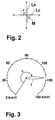
- FIG. 2 of the accompanying drawings shows the operation principle of such a cross-coil meter. The cross-coil meter includes a magnet M and two exciting coils Ls and Lc. The coils Ls, Lc generate magnetic fields having intensities according to currents supplied by a driving system (not shown). These two coils are arranged to be perpendicular to each other. A combined magnetic field composed of the magnetic fields of these coils Ls, Lc is controlled by regulating the currents which are applied to these coils. The magnet M is located so as to be actuated by the combined magnetic field. When it is actuated, the magnet M generates torque, angularly moving according to the torque. A non-illustrated pointer is connected to the magnet M to deflect in response to the angular movement of the magnet M.
- The pointer deflects according to the currents applied to the coils Ls, Lc. Therefore, when the currents to the coils Ls, Lc change in response to the measured vehicle or engine speed, the pointer deflects to indicate the varying vehicle or engine speed. FIG. 3 of the accompanying drawings shows a speedometer for a vehicle. In FIG. 3, a pointer I is connected to the magnet M of FIG. 2. An angle ϑ corresponds to the angle by which the magnet M is moved due to the combined magnetic field generated by the coils Ls, Lc.
- A pulse output type sensor is usually used for detecting the vehicle or engine speed. Some speed sensors generate pulse signals having different frequencies according to detected speeds. When a cross-coil meter is set in motion by an output from such a sensor, it is necessary to use a counter for counting the frequency of pulses, a modulator for performing the pulse width modulation (PWM) according to the counted results of the counter, a driver for supplying PWM-modulated currents to the coils Ls, Lc, and so forth. To deflect the pointer I by the angle ϑ according to the value detected by the sensor, a ROM or the like should be used to correspond the counted frequencies with the deflection angle ϑ.
- Usually inputs from the sensor are variable to a certain extent. To operate the cross-coil meter, such variable inputs should preferably be stabilized to prevent unfavorable deflection of the pointer I. For this purpose, the counted frequency of pulses are conventionally averaged in a specified period of time, so that the deflection angle ϑ of the pointer is controlled by a mean value. A frequency Fn at a certain time point is determined by the following formula.

where a is an integer, Fin is an input frequency, Fn-1 is a frequency which serves as a base for determining the deflection angle ϑ at the time point n-1, Fn-2 is another frequency serving as another base for determining the deflection angle ϑ, and so forth. - When this equation is employed, the calculation results (Fn-1 to Fn-a) should be obtained until the time point a, which means a slow response. To improve the response, a formula for obtaining a weight average has been studied and in use now.

where α is a constant (0 < α < 1). - However, even when Fn is obtained by using the second formula, the foregoing calculation has to be repeated each time a new frequency is counted by the counter, resulting in too quick a response in some cases, or too slow a response in other cases. For example, when a cross-coil meter is operated by a sensor for outputting high frequency pulses, the number of calculations per unit time is increased to make the pointer I fluctuate extensively. Otherwise, the number of calculations per unit time becomes too few to reduce the pointer's responsiveness.
- It is therefore an object of the invention to provide a meter which is very responsive to any variation in input frequency but can prevent unnecessary fluctuation of its pointer.
- According to the invention, there is provided a meter driving system comprising: means for weight-averaging measured frequency or period values of input signals and a present meter indication so as to successively renew the meter indication; and means for varying a weight for renewing the meter indication according to the measured frequency or period values of the input signal so that fluctuation of the meter indication is accordingly suppressed when high signal frequencies are inputted, and fluctuation of the meter indication is accordingly enhanced when low signal frequencies are inputted.
- With this arrangement, the meter can give an accurate indication irrespective of varying input signal frequencies.
- The driving system of the invention further includes: a reference clock generator for generating reference clock signals having a predetermined period; a counter for counting the number of the reference clock signals generated within a predetermined number of the periods of the input signal so as to output the counted results as data representing the period of the input signal; and means for measuring the frequency of the input signals based on the counted results of the counting means.
- The frequencies or periods of the input signals are measured by the counter according to the number of reference clock signals which are generated during a specified period of the input signal.
- To renew the meter indication, the output values are obtained by weight-averaging the measured values. Then the output values are weight-averaged to determine the indication to be given. Different weights may be used to calculate the output value and to obtain the indication based on the calculated output values.
- To operate indicating means such as a cross-coil meter having a pointer, a deflection angle of the pointer is firstly determined based on the indication to be given. Then, the pointer is angularly moved according to the determined deflection angle.
- When the indication means has a plurality of exciting coils, effective values of exciting current to these coils are controlled, being supplied to the coils. Means for determining the signs of the exciting currents may be used when the exciting currents are controlled by pulse width modulation.
-
- FIG. 1 is a block diagram showing the configuration of a drive meter according to the invention;
- FIG. 2 shows the principle of a cross-coil meter; and
- FIG. 3 shows an example of an indication given by a speed meter.
- FIG. 1 shows a driving system for operating a meter of the invention. The driving system receives signals from a pulse output type sensor to drive a
cross-coil meter 26. - Signals from the sensor are firstly counted by a
binary counter 10, which recognizes a period of the received signals based on reference clock signals generated by areference clock generator 12. When the signals from the sensor have the period Tin, thebinary counter 10 counts the number of pulses generated between the rise and immediate fall of the signals from the sensor. Thus, a half period Tin/2 of the sensor signals is detected with specified precision. Thebinary counter 10 may count the number of reference pulses generated between the fall and immediate rise of the signals from the sensor. Thebinary counter 10 may also count intervals between falls of the signals from the sensor. Tie driving system of FIG. 1 can perform these counting operations. - A
latch 14 latches the counted results of thebinary counter 10. Latch timing corresponds to the timing of rise or fall of the signals from the sensor. The rise or fall timing of the signals is selected as the latch timing depending on which of the three foregoing operations is executed by thebinary counter 10. The value latched by thelatch 14 directly or indirectly represents the period Tin of the signals outputted by the sensor. Since the period Tin is a reciprocal of a frequency Fin, the value latched by thelatch 14 is a value of the frequency Fin. The reference clock signals are also supplied to aCPU 16 andPWM modulator 22 for synchronization, as described later. - The
CPU 16 performs the calculations based on the value latched by thelatch 14, i.e. data representing the period Tin or frequency Fin of the signal outputted by the sensor, thereby controlling the indication to be given by thecross-coil meter 26. - The
CPU 16 performs its control operation according to a preset program. Specifically, theCPU 16 is connected to aROM 20 for storing the calculation program. TheROM 20 stores riot only the calculation program but also various coefficients (such as β and αm) to be used for the calculations. TheCPU 16 executes the control calculations while storing inRAM 18 intermediate aspects or results of the calculations. - The
CPU 16 controls the indication of thecross-coil meter 26 as follows. - Firstly, the
CPU 16 reads the data latched by thelatch 14. The data represent the period Tin or frequency Fin of the signals outputted by the sensor as described above. Then, theCPU 16 determines the output value Fn based on the period Tin or frequency Fin. - The
CPU 16 determines the output value Fn by using a response coefficient β which is a feature of the invention. The following formula is used for this purpose.


where β is a constant. TheCPU 16 determines the output value Fn based on the frequency Fin by using the formulas (2) and (3). - As can be seen from the formula (2), when the frequency Fin of the pulse signals from the sensor is high, the weight α of Fn-1 in the formula (3) is approximate to 1, i.e. the weight becomes heavy. On the contrary, the weight (1-α) of the frequency Fin becomes light. The output value Fn of the
CPU 16 tends to deviate from the frequency Fin of the pulse signal as the frequency Fin becomes high. - The
CPU 16 stores the output value Fn as Fn-1 inRAM 18. In other words, Fn-1 is renewed in theRAM 18. TheCPU 16 also calculates and outputs a value Fm to be indicated. - The
PWM modulator 22 has a register for storing the value Fm to be indicated. This register is not shown in FIG. 1. The value Fm is calculated by using the weight-averaging formula (4).

where αm is a constant. TheCPU 16 uses the value Fm to renew the contents of a register of thePWM modulator 22. - The
PWM modulator 22 determines a deflection angle ϑ of thecross-coil meter 26 based on the value Fm which is calculated by theCPU 16 and stored in the register of thePWM modulator 22. As described above, the period or frequency of the pulse signals from the sensor corresponds to the value detected by the sensor, e.g. speed. Therefore, theCPU 16 calculates the value Fm by using the foregoing formulas, determining the deflection angle ϑ of thecross-coil meter 26 so that the detected value of the sensor is indicated by thecross-coil meter 26. ThePMM modulator 22 determines the deflection angle ϑ by referring to a table (not shown) in the memory. - The
PWM modulator 22 generates two kinds of signals, sine and cosine signals, based on the deflection angle ϑ, outputting these signals to adriver 28. Thedriver 28 operates thecross-coil meter 26 in response to the received sine and cosine signals. Specifically, thePWM modulator 22 supplies thedriver 28 with the sine and cosine signals representing the absolute values of sin ϑ and cos ϑ. Then, thedriver 28 provides the two coils of thecross-coil meter 26 with currents having effective values corresponding to the two PWM signals, respectively. - The
driver 28 requires information concerning the signs of sin ϑ and cos ϑ. Asteering logic 24 determines the signs of sin ϑ and cos ϑ based on the output value Fn and the value Fm (to be indicated), thereby supplying them to thedriver 28. When the value Fm to be indicated is in the first quadrant, both sin ϑ and cos ϑ are positive. Therefore, thesteering logic 24 sendstie driver 28 the signals denoting that the signals sin ϑ and cos ϑ are positive. Receiving the sine and cosine signals from thePWM modulator 22 and signals representing the signs of these signals, thedriver 28 operates thecross-coil meter 26 accordingly. - In the foregoing embodiment, the weight coefficient α in the formula (3) is determined according to the frequency Fin when the
CPU 16 calculates the output value Fn. The higher the frequency Fin, the less thecross-coil meter 26 is responsive to the input from the sensor so as to indicate the value Fm precisely. It is therefore possible to overcome the inconvenience with conventional meters that the higher the input frequency Fin, the more extensively themeter 26 tends to deflect its pointer. - The lower the frequency Fin, the more the
meter 26 becomes responsive to the input from the sensor so as to give an accurate indication of the value Fm. - The invention being thus described, it will be obvious that the sane may be varied in many ways. Such variations are not to be considered as a departure from the spirit and scope of the invention, and all such modifications as would be obvious to one skilled in the art are intended to be included within the scope of the following claims.
Claims (20)
- A meter driving system comprising:(a) means for weight-averaging measured frequency values of input signals and a present meter indication so as to successively renew the meter indication; and(b) means for varying a weight for renewing the meter indication according to the measured frequency values of the input signals so that fluctuation of the meter indication is accordingly suppressed when high signal frequencies are inputted, and fluctuation of the meter indication is accordingly enhanced when low signal frequencies are inputted.
- A meter driving system according to claim 1, further including means for measuring the frequencies of the input signals.
- A meter driving system according to claim 2, wherein said frequency measuring means includes:
a reference clock generator for generating reference clock signals having a predetermined period;
means for counting the number of the reference clock signals generated within a predetermined number of the periods of the input signals so as to output the counted results as data representing the period of the input signals; and
means for calculating frequencies of the input signals based on the measured results of said counting means. - A meter driving unit comprising:(a) means for weight-averaging measured values of periods of input signals and a present meter indication so as to successively renew the meter indication; and(b) means for varying a weight for renewing the meter indication according to the measured values of periods of the input signals so that fluctuation of the meter indication is accordingly suppressed when high signal frequencies are inputted, and fluctuation of the meter indication is accordingly enhanced when low signal frequencies are inputted.
- A meter driving system according to claim 4, further including means for measuring the period of the input signals.
- A meter driving system according to claim 5, wherein said period measuring means includes:
a reference clock generator for generating reference clock signals having a predetermined period; and
means for counting the number of the reference clock signals generated within a predetermined number of the periods of the input signals so as to output the counted results as data representing the period of the input signals. - A meter driving system comprising:(a) means for weight-averaging measured values of frequencies of input signals and a present output value so as to successively renew the output value;(b) means for varying a weight for renewing the output value according to the measured frequency values of the input signal so that fluctuation of the meter indication is accordingly suppressed when high signal frequencies are inputted, and fluctuation of the meter indication is accordingly enhanced when low signal frequencies are inputted; and(c) means for weight-averaging the output values and the present meter indication so as to renew the meter indication.
- A meter driving system according to claim 7, further including means for measuring the frequencies of the input signals.
- A meter driving system according to claim 8, wherein said frequency measuring means includes:
a reference clock generator for generating reference clock signals having a predetermined period;
means for counting the number of the reference clock signals generated within a predetermined number of the periods of the input signals so as to output the counted results as data representing the period of the input signals; and
means for calculating frequencies of the input signals based on the counted results of said counting means. - A meter driving system comprising:(a) means for weight-averaging measured values of periods of input signals and a present output value so as to successively renew the output value;(b) means for varying a weight for renewing the output values according to the measured values of the period of the input signal so that fluctuation of the meter indication is accordingly suppressed when high signal frequencies are inputted, and fluctuation of the meter indication is accordingly enhanced when low signal frequencies are inputted; and(c) means for weight-averaging the output value and a present meter indication so as to renew the meter indication successively.
- A meter driving system according to claim 10, further including means for measuring the period of the input signals.
- A meter driving system according to claim 10, wherein said period measuring means includes:
a reference clock generator for generating reference clock signals having a predetermined period; and
means for counting the number of the reference clock signals generated within a predetermined number of the periods of the input signals so as to output the counted results as data representing the period of the input signal. - A meter comprising:(a) means for weight-averaging measured frequency values of input signals and a present meter indication so as to successively renew the meter indication; and(b) means for varying a weight for renewing the meter indication according to the measured freqeuncy values of the input signals so that fluctuation of the meter indication is accordingly suppressed when high signal frequencies are inputted, and fluctuation of the meter indication is accordingly enhanced when low signal frequencies are inputted; and(c) indicating means for giving a successively renewed indication by a pointer.
- A meter according to claim 13, further including means for determining an angle to move said pointer according to the indication to be given, and means for moving said pointer by the determined angle.
- A meter according to claim 13, wherein said indicating means includes a plurality of exciting coils, and said pointer moving means includes a member for calculating effective values of exciting currents according to the determined deflection angle, and a member for controlling the exciting currents to be supplied to said exciting coils according to the calculated effective values of the exciting currents.
- A meter according to claim 14, wherein said pointer moving means includes a member for determining the signs of the exciting currents according to the determined deflection angle of said pointer.
- A meter comprising:(a) means for weight-averaging measured values of periods of input signals and a present meter indication so as to successively renew the meter indication; and(b) means for varying a weight for renewing the meter indication according to the measured values of the period of the input signals so that fluctuation of the meter indication is accordingly suppressed when high signal frequencies are inputted, and fluctuation of the meter indication is accordingly enhanced when low signal frequencies are inputted; and(c) indicating means for giving a successively renewed indication.
- A meter according to claim 17, further including means for determining an angle to move said pointer according to the indication to be given, and means for moving said pointer by the determined angle.
- A meter according to claim 18, wherein said indicating means includes a plurality of exciting coils, and said pointer moving means includes a member for calculating effective values of exciting currents according to the determined deflection angle, and a member for controlling the exciting currents to be supplied to said exciting coils according to the calculated effective values of the exciting currents.
- A meter according to claim 18, wherein said pointer moving means includes a member for determining the signs of the exciting currents according to the determined deflection angle of said pointer.
Applications Claiming Priority (2)
| Application Number | Priority Date | Filing Date | Title |
|---|---|---|---|
| JP61924/91 | 1991-03-26 | ||
| JP3061924A JP2525963B2 (en) | 1991-03-26 | 1991-03-26 | Meter drive |
Publications (2)
| Publication Number | Publication Date |
|---|---|
| EP0505826A1 true EP0505826A1 (en) | 1992-09-30 |
| EP0505826B1 EP0505826B1 (en) | 1995-04-05 |
Family
ID=13185197
Family Applications (1)
| Application Number | Title | Priority Date | Filing Date |
|---|---|---|---|
| EP92104102A Expired - Lifetime EP0505826B1 (en) | 1991-03-26 | 1992-03-10 | Meter driving method |
Country Status (4)
| Country | Link |
|---|---|
| US (1) | US5218291A (en) |
| EP (1) | EP0505826B1 (en) |
| JP (1) | JP2525963B2 (en) |
| DE (1) | DE69201897T2 (en) |
Families Citing this family (4)
| Publication number | Priority date | Publication date | Assignee | Title |
|---|---|---|---|---|
| US5315536A (en) * | 1991-04-09 | 1994-05-24 | Rohm Co., Ltd. | Meter driving system |
| JPH0650992A (en) * | 1992-07-30 | 1994-02-25 | Rohm Co Ltd | Meter driver |
| JP3278525B2 (en) * | 1994-02-28 | 2002-04-30 | 株式会社東芝 | Frequency data conversion device and meter device |
| JPH1172513A (en) * | 1997-08-28 | 1999-03-16 | Nippon Seiki Co Ltd | Pointer indicator |
Citations (3)
| Publication number | Priority date | Publication date | Assignee | Title |
|---|---|---|---|---|
| US4485452A (en) * | 1982-03-22 | 1984-11-27 | The Bendix Corporation | Speed measurement system |
| EP0379816A1 (en) * | 1988-12-19 | 1990-08-01 | Jaeger | Control for crossed-coil instruments |
| EP0413891A2 (en) * | 1989-08-24 | 1991-02-27 | VDO Adolf Schindling AG | Process and appliance forming an input signal for a crossed-coil type indicating instrument |
Family Cites Families (8)
| Publication number | Priority date | Publication date | Assignee | Title |
|---|---|---|---|---|
| JPS5631652A (en) * | 1979-08-24 | 1981-03-31 | Nissan Motor Co Ltd | Display unit for automobile |
| US4356445A (en) * | 1980-07-10 | 1982-10-26 | Cherry Semiconductor Corporation | Method and apparatus for driving air core meter movements |
| JPS63145969A (en) * | 1986-07-31 | 1988-06-18 | Nippon Seiki Co Ltd | Cross coil and movable magnet type measuring instrument |
| JPS6459162A (en) * | 1987-08-31 | 1989-03-06 | Japan Engine Valve Mfg | Cross coil type mobile magnet instrument |
| JPH0711538B2 (en) * | 1988-02-05 | 1995-02-08 | ジェコー株式会社 | Driving circuit for crossed coil type instrument |
| JPH0675077B2 (en) * | 1988-11-24 | 1994-09-21 | ローム株式会社 | Meter drive |
| US4939675A (en) * | 1988-12-22 | 1990-07-03 | Chrysler Corporation | Digital system for controlling mechanical instrument gauges |
| US5051688A (en) * | 1989-12-20 | 1991-09-24 | Rohm Co., Ltd. | Crossed coil meter driving device having a plurality of input parameters |
-
1991
- 1991-03-26 JP JP3061924A patent/JP2525963B2/en not_active Expired - Fee Related
-
1992
- 1992-02-26 US US07/841,478 patent/US5218291A/en not_active Expired - Lifetime
- 1992-03-10 DE DE69201897T patent/DE69201897T2/en not_active Expired - Fee Related
- 1992-03-10 EP EP92104102A patent/EP0505826B1/en not_active Expired - Lifetime
Patent Citations (3)
| Publication number | Priority date | Publication date | Assignee | Title |
|---|---|---|---|---|
| US4485452A (en) * | 1982-03-22 | 1984-11-27 | The Bendix Corporation | Speed measurement system |
| EP0379816A1 (en) * | 1988-12-19 | 1990-08-01 | Jaeger | Control for crossed-coil instruments |
| EP0413891A2 (en) * | 1989-08-24 | 1991-02-27 | VDO Adolf Schindling AG | Process and appliance forming an input signal for a crossed-coil type indicating instrument |
Non-Patent Citations (1)
| Title |
|---|
| PATENT ABSTRACTS OF JAPAN vol. 8, no. 159 (P-289)(1596) 24 July 1984 & JP-A-59 057 163 ( TOSHIBA KK ) 2 April 1984 * |
Also Published As
| Publication number | Publication date |
|---|---|
| DE69201897T2 (en) | 1995-11-16 |
| US5218291A (en) | 1993-06-08 |
| DE69201897D1 (en) | 1995-05-11 |
| JP2525963B2 (en) | 1996-08-21 |
| JPH04296659A (en) | 1992-10-21 |
| EP0505826B1 (en) | 1995-04-05 |
Similar Documents
| Publication | Publication Date | Title |
|---|---|---|
| US5051688A (en) | Crossed coil meter driving device having a plurality of input parameters | |
| US4706083A (en) | Fuel economy indicator | |
| US4380733A (en) | Frequency and speed display device | |
| US4991098A (en) | Computer-based controller and bipolar PWM driver arrangement for air core gauge control | |
| EP0357098B1 (en) | Coriolis mass flow meter having absolute frequency output and method for providing a frequency output signal | |
| JP3013775B2 (en) | Driving device for stepping motor type instrument | |
| EP0529523A1 (en) | Multiple-meter driving apparatus | |
| US5315536A (en) | Meter driving system | |
| EP0068704B1 (en) | Speed meter systems | |
| US5218291A (en) | Meter and meter driving system with indication fluctuation suppression and enhancement | |
| KR970010004B1 (en) | Cross Coil Type Magnetic Magnetic Instrument | |
| US4841238A (en) | Gauge driving system | |
| JPS6130770A (en) | Vehicle detector | |
| EP0509484B1 (en) | PWM modulation circuit for a cross-coil meter driver | |
| US5448163A (en) | Meter drive including a timer for generating update cycles at a frequency larger than the input clock pulses and digital filtering | |
| EP0145280B1 (en) | Fuel economy indicator | |
| SU1040417A1 (en) | Angular speed measuring device | |
| KR100537265B1 (en) | Method for driving meter | |
| JP3106462B2 (en) | Driving device for indicating instrument | |
| JPH1123603A (en) | Driver for stepping motor type instrument | |
| JPH0778508B2 (en) | Meter drive | |
| KR100278514B1 (en) | Combimeter system drive | |
| SU1049432A1 (en) | Three-component accelerometer | |
| SU1495173A1 (en) | Device for monitoring vehicle path variables | |
| SU847204A1 (en) | Device for determining movement parameter deviation from those set by schedule |
Legal Events
| Date | Code | Title | Description |
|---|---|---|---|
| PUAI | Public reference made under article 153(3) epc to a published international application that has entered the european phase |
Free format text: ORIGINAL CODE: 0009012 |
|
| AK | Designated contracting states |
Kind code of ref document: A1 Designated state(s): DE FR GB |
|
| 17P | Request for examination filed |
Effective date: 19920811 |
|
| 17Q | First examination report despatched |
Effective date: 19940127 |
|
| GRAA | (expected) grant |
Free format text: ORIGINAL CODE: 0009210 |
|
| AK | Designated contracting states |
Kind code of ref document: B1 Designated state(s): DE FR GB |
|
| REF | Corresponds to: |
Ref document number: 69201897 Country of ref document: DE Date of ref document: 19950511 |
|
| ET | Fr: translation filed | ||
| PLBE | No opposition filed within time limit |
Free format text: ORIGINAL CODE: 0009261 |
|
| STAA | Information on the status of an ep patent application or granted ep patent |
Free format text: STATUS: NO OPPOSITION FILED WITHIN TIME LIMIT |
|
| 26N | No opposition filed | ||
| REG | Reference to a national code |
Ref country code: GB Ref legal event code: IF02 |
|
| PGFP | Annual fee paid to national office [announced via postgrant information from national office to epo] |
Ref country code: GB Payment date: 20030305 Year of fee payment: 12 |
|
| PGFP | Annual fee paid to national office [announced via postgrant information from national office to epo] |
Ref country code: FR Payment date: 20030310 Year of fee payment: 12 |
|
| PGFP | Annual fee paid to national office [announced via postgrant information from national office to epo] |
Ref country code: DE Payment date: 20030320 Year of fee payment: 12 |
|
| PG25 | Lapsed in a contracting state [announced via postgrant information from national office to epo] |
Ref country code: GB Free format text: LAPSE BECAUSE OF NON-PAYMENT OF DUE FEES Effective date: 20040310 |
|
| PG25 | Lapsed in a contracting state [announced via postgrant information from national office to epo] |
Ref country code: DE Free format text: LAPSE BECAUSE OF NON-PAYMENT OF DUE FEES Effective date: 20041001 |
|
| GBPC | Gb: european patent ceased through non-payment of renewal fee |
Effective date: 20040310 |
|
| PG25 | Lapsed in a contracting state [announced via postgrant information from national office to epo] |
Ref country code: FR Free format text: LAPSE BECAUSE OF NON-PAYMENT OF DUE FEES Effective date: 20041130 |
|
| REG | Reference to a national code |
Ref country code: FR Ref legal event code: ST |