EP0505454B1 - Container for fan-folded sheets - Google Patents
Container for fan-folded sheets Download PDFInfo
- Publication number
- EP0505454B1 EP0505454B1 EP19910901380 EP91901380A EP0505454B1 EP 0505454 B1 EP0505454 B1 EP 0505454B1 EP 19910901380 EP19910901380 EP 19910901380 EP 91901380 A EP91901380 A EP 91901380A EP 0505454 B1 EP0505454 B1 EP 0505454B1
- Authority
- EP
- European Patent Office
- Prior art keywords
- chamber
- sheets
- container
- elongated
- narrow channel
- Prior art date
- Legal status (The legal status is an assumption and is not a legal conclusion. Google has not performed a legal analysis and makes no representation as to the accuracy of the status listed.)
- Expired - Lifetime
Links
Images


Classifications
-
- B—PERFORMING OPERATIONS; TRANSPORTING
- B65—CONVEYING; PACKING; STORING; HANDLING THIN OR FILAMENTARY MATERIAL
- B65H—HANDLING THIN OR FILAMENTARY MATERIAL, e.g. SHEETS, WEBS, CABLES
- B65H35/00—Delivering articles from cutting or line-perforating machines; Article or web delivery apparatus incorporating cutting or line-perforating devices, e.g. adhesive tape dispensers
- B65H35/10—Delivering articles from cutting or line-perforating machines; Article or web delivery apparatus incorporating cutting or line-perforating devices, e.g. adhesive tape dispensers from or with devices for breaking partially-cut or perforated webs, e.g. bursters
-
- B—PERFORMING OPERATIONS; TRANSPORTING
- B65—CONVEYING; PACKING; STORING; HANDLING THIN OR FILAMENTARY MATERIAL
- B65D—CONTAINERS FOR STORAGE OR TRANSPORT OF ARTICLES OR MATERIALS, e.g. BAGS, BARRELS, BOTTLES, BOXES, CANS, CARTONS, CRATES, DRUMS, JARS, TANKS, HOPPERS, FORWARDING CONTAINERS; ACCESSORIES, CLOSURES, OR FITTINGS THEREFOR; PACKAGING ELEMENTS; PACKAGES
- B65D83/00—Containers or packages with special means for dispensing contents
- B65D83/08—Containers or packages with special means for dispensing contents for dispensing thin flat articles in succession
- B65D83/0847—Containers or packages with special means for dispensing contents for dispensing thin flat articles in succession through an aperture at the junction of two walls
-
- B—PERFORMING OPERATIONS; TRANSPORTING
- B65—CONVEYING; PACKING; STORING; HANDLING THIN OR FILAMENTARY MATERIAL
- B65H—HANDLING THIN OR FILAMENTARY MATERIAL, e.g. SHEETS, WEBS, CABLES
- B65H2701/00—Handled material; Storage means
- B65H2701/10—Handled articles or webs
- B65H2701/11—Dimensional aspect of article or web
- B65H2701/112—Section geometry
- B65H2701/1123—Folded article or web
- B65H2701/11231—Fan-folded material or zig-zag or leporello
-
- Y—GENERAL TAGGING OF NEW TECHNOLOGICAL DEVELOPMENTS; GENERAL TAGGING OF CROSS-SECTIONAL TECHNOLOGIES SPANNING OVER SEVERAL SECTIONS OF THE IPC; TECHNICAL SUBJECTS COVERED BY FORMER USPC CROSS-REFERENCE ART COLLECTIONS [XRACs] AND DIGESTS
- Y10—TECHNICAL SUBJECTS COVERED BY FORMER USPC
- Y10T—TECHNICAL SUBJECTS COVERED BY FORMER US CLASSIFICATION
- Y10T225/00—Severing by tearing or breaking
- Y10T225/20—Severing by manually forcing against fixed edge
- Y10T225/205—With feed-out of predetermined length from work supply
- Y10T225/21—Merely to provide lead-end for manual grasping
-
- Y—GENERAL TAGGING OF NEW TECHNOLOGICAL DEVELOPMENTS; GENERAL TAGGING OF CROSS-SECTIONAL TECHNOLOGIES SPANNING OVER SEVERAL SECTIONS OF THE IPC; TECHNICAL SUBJECTS COVERED BY FORMER USPC CROSS-REFERENCE ART COLLECTIONS [XRACs] AND DIGESTS
- Y10—TECHNICAL SUBJECTS COVERED BY FORMER USPC
- Y10T—TECHNICAL SUBJECTS COVERED BY FORMER US CLASSIFICATION
- Y10T225/00—Severing by tearing or breaking
- Y10T225/20—Severing by manually forcing against fixed edge
- Y10T225/23—Zigzag-folded supply package
-
- Y—GENERAL TAGGING OF NEW TECHNOLOGICAL DEVELOPMENTS; GENERAL TAGGING OF CROSS-SECTIONAL TECHNOLOGIES SPANNING OVER SEVERAL SECTIONS OF THE IPC; TECHNICAL SUBJECTS COVERED BY FORMER USPC CROSS-REFERENCE ART COLLECTIONS [XRACs] AND DIGESTS
- Y10—TECHNICAL SUBJECTS COVERED BY FORMER USPC
- Y10T—TECHNICAL SUBJECTS COVERED BY FORMER US CLASSIFICATION
- Y10T225/00—Severing by tearing or breaking
- Y10T225/20—Severing by manually forcing against fixed edge
- Y10T225/238—With housing for work supply
- Y10T225/254—With finger-access opening to facilitate work feed-out
-
- Y—GENERAL TAGGING OF NEW TECHNOLOGICAL DEVELOPMENTS; GENERAL TAGGING OF CROSS-SECTIONAL TECHNOLOGIES SPANNING OVER SEVERAL SECTIONS OF THE IPC; TECHNICAL SUBJECTS COVERED BY FORMER USPC CROSS-REFERENCE ART COLLECTIONS [XRACs] AND DIGESTS
- Y10—TECHNICAL SUBJECTS COVERED BY FORMER USPC
- Y10T—TECHNICAL SUBJECTS COVERED BY FORMER US CLASSIFICATION
- Y10T225/00—Severing by tearing or breaking
- Y10T225/20—Severing by manually forcing against fixed edge
- Y10T225/238—With housing for work supply
- Y10T225/255—With internal guide
Definitions
- This invention relates generally to containers for holding small flexible sheets and, more particularly, to containers that allow the sheets to be dispensed, one at a time, from a fan-folded stack, such as are known from e.g. US-A-4 032 004.
- Containers of this kind are particularly useful in the dispensing of hygienic plastic sheet assemblies for use in covering the elongated probe of a clinical thermometer.
- An example of such a protective cover assembly is shown and described in a copending and commonly-assigned U.S.-A-4 911 559, entitled "Disposable Probe Cover Assembly for Medical Thermometer.”
- the probe cover assemblies disclosed in that patent application each have three layers, including a plastic base layer with a central aperture, a stretchable plastic film spanning the aperture, and a protective paper layer.
- the three layers are laminated together to form a flat assembly having at least limited flexibility and having a generally square shape, with well-rounded corners, about 1,91 cm to 2,54 cm (3/4 to 1 inch) across.
- the probe cover assemblies are connected together to form an elongated chain, and the individual covers are folded together in alternating directions to form a fan-folded stack.
- the container should be configured so as to minimize the possibility of the fan-folded stack becoming jammed within it and so that the individual sheets can be effectively dispensed regardless of the number of sheets remaining within the apparatus.
- the container also should be configured such that the individual sheets being dispensed do not inadvertently retract back into the container.
- the container should be inexpensive to manufacture, yet be sufficiently strong to withstand normal handling without damaging its fragile contents. The present invention fulfills these needs.
- the present invention is embodied in a container for hygienically carrying flat flexible sheets such as plastic probe cover assemblies and for allowing the sheets to be dispensed, one at a time, from a uniform fan-folded stack, with minimal risk that the stack will become jammed, according to claim 1.
- the container includes an elongated storage chamber with a cross-sectional shape that corresponds generally with the shape of the individual sheets to be dispensed and a cross-sectional size the permits the stack of fan-folded sheets to slide along the chamber's longitudinal axis.
- An exit slot defined at one end of the elongated chamber is sized to allow the connected sheets to be dispensed end-wise therethrough, one at a time.
- the container includes retainer means spaced rearwardly of the slot for defining a constriction in the elongated chamber having a size slightly smaller than the sheets, so as to retain the stack of fan-folded sheets behind it.
- the sheets can then be individually dispensed by pulling the end-most sheet through the slot, which flexes a trailing sheet past the constriction, with the remaining sheets being retained by the constriction.
- the container is simple and inexpensive to construct, yet completely reliable in effectively dispensing the individual sheets.
- the elongated storage chamber is defined by four walls and the chamber has a generally square transverse cross-section, with well-rounded corners.
- the constriction is defined by ridges projecting inwardly from two opposing side walls, the ridges lying in a common plane, substantially perpendicular to the chamber's longitudinal axis.
- One of the four walls curves smoothly from the constriction to the exit slot.
- pulling the end-most sheet through the slot in turn pulls a trailing sheet in the fan-folded stack past the constriction.
- the inwardly-projecting ridges in the side walls frictionally grip the sheet's side edges as the sheet slides past, to stabilize the sheet and prevent jamming. Eventually, the trailing edge of the sheet is pulled past the constriction and the process repeated with the next succeeding sheet.
- the exit slot is defined by a channel formed by two spaced-apart, confronting walls (i.e., the chamber's top wall and bottom wall), one of the walls including a shallow recess having a rearward edge with a peripheral size and shape conforming with the rearward edge of the sheets being guided through the channel.
- the channel is configured such that a sheet being guided through it is urged into the shallow recess where its rearward edge abuts against the recess' rearward edge and thereby is inhibited from moving rearwardly toward the container.
- the shallow recess has a progressively shallower depth with increasing distance from its rearward edge, such that the recess effectively is a ramp.
- the sheet's rearward edge is urged downwardly into abutment with the shallow recess' rearward edge by two upward projections near the recess' front end.
- the container is defined by two sections, each section being in the form of an elongated trough encircled by a rim, with a flange projecting outwardly from the rim.
- the two sections are attached to each other with their flanges in abutment.
- the two sections preferably are formed from a single sheet of plastic material and are initially pivotally connected together, at the end of the container opposite the slot.
- FIG. 1 is a front perspective view of a probe cover container embodying the invention, with individual plastic probe cover assemblies being dispensed, one at a time, through a slot in the container's forward end.
- FIG. 2 is a top plan view of the container of FIG. 1, shown without the probe cover assemblies.
- FIG. 3 is a side sectional view of the container, taken in the direction of the arrows 3-3 in FIG. 2.
- FIG. 4 is a front elevational view of the container of FIG. 1.
- FIG. 5 is a sectional view of the container, taken in the direction of the arrows 5-5 in FIG. 2, with a probe cover assembly being shown retained behind ridges formed in the container's side walls.
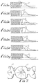
- FIGS. 6(a)-6(g) are schematic views showing the sequential movement of the fan-folded stack of probe cover assemblies as two individual assemblies are successively dispensed.
- FIG. 7 is a plan view of several attached probe cover assemblies of the kind that can be arranged in a fan-folded stack and dispensed individually from the container of FIG. 1.
- Each probe cover assembly (FIG. 7) includes three thin, laminated sheets having a generally square shape, with well-rounded corners, and a transverse dimension of about 1,91 cm-to-2,54 cm (3/4-to-1 inch).
- the assemblies are connected together end-to-end by narrow strips 13 to form an elongated chain and are folded back on each other in an alternating fashion to produce a fan-folded stack adapted to be placed within the container. Thereafter, the probe cover assemblies can be selectively removed from the stack and individually dispensed.
- the container includes a lower section 15 and an upper section 17 that are secured together to define an elongated chamber having a generally square cross-section with well-rounded corners for carrying the stack of fan-folded probe cover assemblies 11.
- a rear portion of the chamber has a generally square cross-section with rounded corners sized to be slightly greater in size than the stack of probe cover assemblies, to allow the stack to slide axially within it.
- An opposite, forward portion of the chamber has a uniform width, but progressively smaller height that terminates in a narrow exit slot 23 located at the container's forward end. The slot is sized to allow the probe cover assemblies to be individually dispensed end-wise therethrough.
- the lower section 15 of the container is shaped like a trough, with a substantially uniform depth along its entire length.
- the section includes a bottom wall 25 and two opposed side walls 27 and 29.
- the rearward end of the lower section includes a rear wall 31, but the forward end is open.
- a flange 33 projects outwardly from the coplanar upper edges of the two side walls 27 and 29 and the rear wall 31.
- the upper section 17 of the container includes a top wall 35, two side walls 37 and 39, and a rear wall 41, which cooperate to define a downwardly-concave portion at the section's rear and a downwardly-convex portion at the section's front.
- the top wall curves smoothly from a generally flat segment at the chamber's rear portion to a generally flat segment at the narrow exit slot 23.
- a flange 43 projects outwardly from coplanar edges of the side walls 37 and 39 and rear wall 41. This flange mates with the flange 33 of the lower section 15, to allow the two sections to be conveniently secured to each other.
- a reliable dispensing of individual probe cover assemblies 11 without jamming in the region of the narrow exit slot 23 is ensured by providing a constriction in the container's chamber 19 in the region where the top wall 35 begins to curve downwardly and the chamber's cross-sectional size begins to diminish.
- inwardly-projecting, coplanar ridges 45a and 45b are located in the respective side walls 37 and 39 of the upper section 17. As best shown in FIG. 5, these ridges cooperate to define an opening that is slightly narrower than the individual probe cover assemblies 11. The stack of assemblies is thereby retained behind the ridges.
- the probe cover assemblies 11 are dispensed through the exit slot 23 by pulling the end-most assembly outwardly. This drags the trailing assemblies behind it, including the particular assembly located at the constriction defined by the ridges 45a and 45b.
- pulling on the end-most assembly causes the assembly located immediately behind the ridges to flex such that its two side edges are pulled past the ridges.
- the ridges frictionally grip the flexed assembly as it is pulled past them, to stabilize the assembly within the container and thereby prevent the assembly from becoming jammed.
- the trailing edge of that assembly remains retained behind the ridges while the assembly pivots forwardly about that trailing edge.
- the trailing edge itself, is pulled past its ridges and the process is then repeated with the next succeeding assembly.
- the top wall initially curves downwardly with a curvature centered at a point generally aligned with the ridges.
- a uniform series of shallow ridges 47 is formed in the bottom wall 25 of the lower section 15, extending along substantially the entire length of the lower section, and a corresponding uniform series of shallow ridges 48 is formed in the top wall 35 of the upper section 17, extending only along the space behind the constricting ridges 45a and 45b.
- These two series of shallow ridges engage the narrow strips 13 interconnecting the successive probe cover assemblies 11 and thereby maintain the stack of fan-folded assemblies oriented generally vertically behind the constricting ridges.
- the shallow ridges 48 located in the portion of the bottom wall forward of the constricting ridges function to prevent an exposed stretchable plastic film in the assemblies from sticking to the bottom wall.
- the shallow ridges 48 also function to longitudinally stiffen the lower section.
- the forward end of the lower section's bottom wall 25 includes a shallow recess 49 having a shape corresponding generally with that of an individual probe cover assembly 11.
- the recess ramps upwardly toward the exit slot 23 at the end of the bottom wall, and a shallow vertical face 50 is thereby defined at the recess' rear periphery.
- the height of the vertical face is made to be slightly greater than the probe cover assembly's thickness, to ensure that the recess' natural radius beneath it does not push the trailing edge of any probe cover assembly located in this recess up and out of the recess. The assembly therefore will abut against this vertical face and be inhibited from being inadvertently moved rearwardly toward the container's chamber.
- the top wall 35 of the container's upper section 17 includes a cutout 53 at its forward end, overlying the shallow recess 49 of the lower section 15.
- This cutout exposes a mid-portion of the upper surface of any probe cover assembly 11 located in the recess, allowing a U-shaped pawl (not shown) to engage the assembly's rearward edge, on opposite sides of the strip 13, and to urge it outwardly through the exit slot 23.
- the pawl retracts to a position where it can engage the rear periphery of the next succeeding assembly.
- a small rearward extension 55 of the shallow recess 49 allows the pawl to drop into a position where it can engage that next assembly's rear periphery.
- the dispenser's lower section 15 and upper section 17 are hinged together at the container's rear end by an integral hinge 57 and are formed from a single sheet of plastic material, e.g., polyvinyl chloride, preferably having a thickness of about 0,25 mm-0,51 mm (.010-.020 inches).
- the sheet can be formed into the specified shape using any of a number of conventional plastic forming techniques.
- the plastic material is preferably transparent, so that the number of stored probe cover assemblies 11 remaining to be dispensed can readily be determined.
- the rear wall 31 and side walls 27 and 29 of the lower section 15 and rear wall 41 and side walls 37 and 39 of the upper section 17 are all formed with a draft of about 5 degrees. This facilitates a convenient removal of the sections from a standard molding apparatus.
- the constricting ridges 45a and 45b of the lower section do not include such a draft, such that their peaks are substantially parallel with each other.
- the present invention provides a container for carrying a fan-folded stack of plastic probe cover assemblies and for allowing the assemblies to be dispensed, one at a time, with minimal risk that the stack will become jammed.
- a shallow recess in a wall defining the narrow channel at the container's forward end conformingly receives a probe cover assembly in position to be dispensed, with the recess' rear periphery inhibiting the assembly from being moved inadvertently back into the chamber.
Landscapes
- Engineering & Computer Science (AREA)
- Mechanical Engineering (AREA)
- Details Of Rigid Or Semi-Rigid Containers (AREA)
- Packages (AREA)
- Containers And Packaging Bodies Having A Special Means To Remove Contents (AREA)
- Walking Sticks, Umbrellas, And Fans (AREA)
- Cartons (AREA)
- Pile Receivers (AREA)
- Control And Other Processes For Unpacking Of Materials (AREA)
- Folding Of Thin Sheet-Like Materials, Special Discharging Devices, And Others (AREA)
Abstract
Description
- This invention relates generally to containers for holding small flexible sheets and, more particularly, to containers that allow the sheets to be dispensed, one at a time, from a fan-folded stack, such as are known from e.g. US-A-4 032 004.
- Containers of this kind are particularly useful in the dispensing of hygienic plastic sheet assemblies for use in covering the elongated probe of a clinical thermometer. An example of such a protective cover assembly is shown and described in a copending and commonly-assigned U.S.-A-4 911 559, entitled "Disposable Probe Cover Assembly for Medical Thermometer." The probe cover assemblies disclosed in that patent application each have three layers, including a plastic base layer with a central aperture, a stretchable plastic film spanning the aperture, and a protective paper layer. The three layers are laminated together to form a flat assembly having at least limited flexibility and having a generally square shape, with well-rounded corners, about 1,91 cm to 2,54 cm (3/4 to 1 inch) across. The probe cover assemblies are connected together to form an elongated chain, and the individual covers are folded together in alternating directions to form a fan-folded stack.
- There is a need for a container for carrying and hygienically protecting a fan-folded stack of flexible sheets such as the probe cover assemblies of the kind described and for allowing the sheets to be dispensed one at a time. The container should be configured so as to minimize the possibility of the fan-folded stack becoming jammed within it and so that the individual sheets can be effectively dispensed regardless of the number of sheets remaining within the apparatus. The container also should be configured such that the individual sheets being dispensed do not inadvertently retract back into the container. In addition, the container should be inexpensive to manufacture, yet be sufficiently strong to withstand normal handling without damaging its fragile contents. The present invention fulfills these needs.
- The present invention is embodied in a container for hygienically carrying flat flexible sheets such as plastic probe cover assemblies and for allowing the sheets to be dispensed, one at a time, from a uniform fan-folded stack, with minimal risk that the stack will become jammed, according to
claim 1. The container includes an elongated storage chamber with a cross-sectional shape that corresponds generally with the shape of the individual sheets to be dispensed and a cross-sectional size the permits the stack of fan-folded sheets to slide along the chamber's longitudinal axis. An exit slot defined at one end of the elongated chamber is sized to allow the connected sheets to be dispensed end-wise therethrough, one at a time. The container includes retainer means spaced rearwardly of the slot for defining a constriction in the elongated chamber having a size slightly smaller than the sheets, so as to retain the stack of fan-folded sheets behind it. The sheets can then be individually dispensed by pulling the end-most sheet through the slot, which flexes a trailing sheet past the constriction, with the remaining sheets being retained by the constriction. The container is simple and inexpensive to construct, yet completely reliable in effectively dispensing the individual sheets. - More particularly, the elongated storage chamber is defined by four walls and the chamber has a generally square transverse cross-section, with well-rounded corners. The constriction is defined by ridges projecting inwardly from two opposing side walls, the ridges lying in a common plane, substantially perpendicular to the chamber's longitudinal axis. One of the four walls curves smoothly from the constriction to the exit slot. In use, pulling the end-most sheet through the slot in turn pulls a trailing sheet in the fan-folded stack past the constriction. The inwardly-projecting ridges in the side walls frictionally grip the sheet's side edges as the sheet slides past, to stabilize the sheet and prevent jamming. Eventually, the trailing edge of the sheet is pulled past the constriction and the process repeated with the next succeeding sheet.
- In accordance with the invention, the exit slot is defined by a channel formed by two spaced-apart, confronting walls (i.e., the chamber's top wall and bottom wall), one of the walls including a shallow recess having a rearward edge with a peripheral size and shape conforming with the rearward edge of the sheets being guided through the channel. The channel is configured such that a sheet being guided through it is urged into the shallow recess where its rearward edge abuts against the recess' rearward edge and thereby is inhibited from moving rearwardly toward the container. More particularly, the shallow recess has a progressively shallower depth with increasing distance from its rearward edge, such that the recess effectively is a ramp. In addition, the sheet's rearward edge is urged downwardly into abutment with the shallow recess' rearward edge by two upward projections near the recess' front end.
- In another feature of the invention, the container is defined by two sections, each section being in the form of an elongated trough encircled by a rim, with a flange projecting outwardly from the rim. The two sections are attached to each other with their flanges in abutment. The two sections preferably are formed from a single sheet of plastic material and are initially pivotally connected together, at the end of the container opposite the slot.
- Other features and advantages of the present invention should become apparent from the following description of the preferred embodiment, taken in conjunction with the accompanying drawings, which illustrate, by way of example, the principles of the invention.
- FIG. 1 is a front perspective view of a probe cover container embodying the invention, with individual plastic probe cover assemblies being dispensed, one at a time, through a slot in the container's forward end.
- FIG. 2 is a top plan view of the container of FIG. 1, shown without the probe cover assemblies.
- FIG. 3 is a side sectional view of the container, taken in the direction of the arrows 3-3 in FIG. 2.
- FIG. 4 is a front elevational view of the container of FIG. 1.
- FIG. 5 is a sectional view of the container, taken in the direction of the arrows 5-5 in FIG. 2, with a probe cover assembly being shown retained behind ridges formed in the container's side walls.
- FIGS. 6(a)-6(g) are schematic views showing the sequential movement of the fan-folded stack of probe cover assemblies as two individual assemblies are successively dispensed.
- FIG. 7 is a plan view of several attached probe cover assemblies of the kind that can be arranged in a fan-folded stack and dispensed individually from the container of FIG. 1.
- With reference now to the drawings, and particularly to FIGS. 1-5, there is shown a container for hygienically carrying a fan-folded stack of thin plastic
probe cover assemblies 11 and for allowing the assemblies to be dispensed, one at a time. Each probe cover assembly (FIG. 7) includes three thin, laminated sheets having a generally square shape, with well-rounded corners, and a transverse dimension of about 1,91 cm-to-2,54 cm (3/4-to-1 inch). The assemblies are connected together end-to-end bynarrow strips 13 to form an elongated chain and are folded back on each other in an alternating fashion to produce a fan-folded stack adapted to be placed within the container. Thereafter, the probe cover assemblies can be selectively removed from the stack and individually dispensed. - The container includes a
lower section 15 and anupper section 17 that are secured together to define an elongated chamber having a generally square cross-section with well-rounded corners for carrying the stack of fan-foldedprobe cover assemblies 11. A rear portion of the chamber has a generally square cross-section with rounded corners sized to be slightly greater in size than the stack of probe cover assemblies, to allow the stack to slide axially within it. An opposite, forward portion of the chamber has a uniform width, but progressively smaller height that terminates in anarrow exit slot 23 located at the container's forward end. The slot is sized to allow the probe cover assemblies to be individually dispensed end-wise therethrough. - The
lower section 15 of the container is shaped like a trough, with a substantially uniform depth along its entire length. The section includes abottom wall 25 and two opposedside walls rear wall 31, but the forward end is open. Aflange 33 projects outwardly from the coplanar upper edges of the twoside walls rear wall 31. - The
upper section 17 of the container includes atop wall 35, twoside walls rear wall 41, which cooperate to define a downwardly-concave portion at the section's rear and a downwardly-convex portion at the section's front. In particular, the top wall curves smoothly from a generally flat segment at the chamber's rear portion to a generally flat segment at thenarrow exit slot 23. Aflange 43 projects outwardly from coplanar edges of theside walls rear wall 41. This flange mates with theflange 33 of thelower section 15, to allow the two sections to be conveniently secured to each other. - In accordance with the invention, a reliable dispensing of individual
probe cover assemblies 11 without jamming in the region of thenarrow exit slot 23 is ensured by providing a constriction in the container's chamber 19 in the region where thetop wall 35 begins to curve downwardly and the chamber's cross-sectional size begins to diminish. In particular, inwardly-projecting,coplanar ridges respective side walls upper section 17. As best shown in FIG. 5, these ridges cooperate to define an opening that is slightly narrower than the individualprobe cover assemblies 11. The stack of assemblies is thereby retained behind the ridges. - In use, the
probe cover assemblies 11 are dispensed through theexit slot 23 by pulling the end-most assembly outwardly. This drags the trailing assemblies behind it, including the particular assembly located at the constriction defined by theridges - As best observed in FIG. 3, a uniform series of
shallow ridges 47 is formed in thebottom wall 25 of thelower section 15, extending along substantially the entire length of the lower section, and a corresponding uniform series ofshallow ridges 48 is formed in thetop wall 35 of theupper section 17, extending only along the space behind the constrictingridges narrow strips 13 interconnecting the successiveprobe cover assemblies 11 and thereby maintain the stack of fan-folded assemblies oriented generally vertically behind the constricting ridges. Theshallow ridges 48 located in the portion of the bottom wall forward of the constricting ridges function to prevent an exposed stretchable plastic film in the assemblies from sticking to the bottom wall. Theshallow ridges 48 also function to longitudinally stiffen the lower section. - In accordance with the invention, and as best depicted in FIGS. 2 and 3, the forward end of the lower section's
bottom wall 25 includes ashallow recess 49 having a shape corresponding generally with that of an individualprobe cover assembly 11. The recess ramps upwardly toward theexit slot 23 at the end of the bottom wall, and a shallowvertical face 50 is thereby defined at the recess' rear periphery. The height of the vertical face is made to be slightly greater than the probe cover assembly's thickness, to ensure that the recess' natural radius beneath it does not push the trailing edge of any probe cover assembly located in this recess up and out of the recess. The assembly therefore will abut against this vertical face and be inhibited from being inadvertently moved rearwardly toward the container's chamber. - At the forward end of the
shallow recess 49 are two upwardly-projectingbumps 51 that urge upwardly the forward end of anyprobe cover assembly 11 located in the recess. This further ensures that the assembly is not inadvertently moved rearwardly toward the chamber. - In another feature of the invention, best depicted in FIGS. 1 and 2, the
top wall 35 of the container'supper section 17 includes acutout 53 at its forward end, overlying theshallow recess 49 of thelower section 15. This cutout exposes a mid-portion of the upper surface of anyprobe cover assembly 11 located in the recess, allowing a U-shaped pawl (not shown) to engage the assembly's rearward edge, on opposite sides of thestrip 13, and to urge it outwardly through theexit slot 23. Following the forcible advancement of each probe cover assembly out through the exit slot, the pawl retracts to a position where it can engage the rear periphery of the next succeeding assembly. A smallrearward extension 55 of theshallow recess 49 allows the pawl to drop into a position where it can engage that next assembly's rear periphery. - As best shown in FIGS. 1 and 3, the dispenser's
lower section 15 andupper section 17 are hinged together at the container's rear end by anintegral hinge 57 and are formed from a single sheet of plastic material, e.g., polyvinyl chloride, preferably having a thickness of about 0,25 mm-0,51 mm (.010-.020 inches). The sheet can be formed into the specified shape using any of a number of conventional plastic forming techniques. In addition, the plastic material is preferably transparent, so that the number of storedprobe cover assemblies 11 remaining to be dispensed can readily be determined. - The
rear wall 31 andside walls lower section 15 andrear wall 41 andside walls upper section 17 are all formed with a draft of about 5 degrees. This facilitates a convenient removal of the sections from a standard molding apparatus. However, the constrictingridges - It should be appreciated from the foregoing description that the present invention provides a container for carrying a fan-folded stack of plastic probe cover assemblies and for allowing the assemblies to be dispensed, one at a time, with minimal risk that the stack will become jammed. A shallow recess in a wall defining the narrow channel at the container's forward end conformingly receives a probe cover assembly in position to be dispensed, with the recess' rear periphery inhibiting the assembly from being moved inadvertently back into the chamber.
- Although the invention has been described in detail with reference to the presently preferred embodiment, those of ordinary skill in the art will appreciate that various modifications can be made without departing from the invention. Accordingly, the invention is defined only by the following claims.
Claims (18)
- A container for carrying a plurality of flat, flexible sheets (11) and for allowing the sheets to be dispensed, one at a time, wherein the sheets are substantially identical and are connected together end-to-end to form an elongated chain, the container comprising:
means (15,17) defining a chamber (19) for carrying a plurality of substantially identical, flat, flexible sheets (11) connected end-to-end to form an elongated chain, each of the sheets having a predetermined peripheral shape; and
means (25,35) defining a narrow channel for guiding the chain of sheets from the chamber;
wherein the chamber and the narrow channel are configured such that pulling the end-most sheet forwardly through the channel pulls with it a trailing sheet from the chamber into the channel;
wherein the means defining a narrow channel includes two spaced-apart, confronting walls (25,35), characterised in that one of the walls (25) includes a shallow recess (49) having a rear periphery with a size and shape conforming with the rear periphery of the individual sheets being guided through the channel;
and that the means defining a narrow channel further includes a means (51) for urging a sheet located in the channel into the shallow recess, such that the sheet's rear periphery abuts against the recess' rear periphery and is inhibited from moving rearwardly into the chamber. - A container as defined in Claim 1, wherein:
the flat sheets (11) each include multiple layers, one of which is of limited flexibility, each sheet having a generally square periphery with rounded corners; and
the shallow recess (49) formed in one wall (25) of the means defining the narrow channel has a corresponding square periphery with rounded corners. - A container as defined in Claim 1, wherein the shallow recess (49) formed in one wall (25) of the means defining the narrow channel has a progressively shallower depth with increasing distance from its rear periphery.
- A container as defined in Claim 1, wherein the means for urging includes two projections (51) projecting into the channel.
- A container as defined in Claim 1, wherein:
the individual sheets (11) in the elongated chain are folded back on each other in an alternating fashion to form a fan-folded stack; and
the chamber is sized and shaped to loosely carry the fan-folded stack of sheets, such that the stack is slidable axially within it and unfolds as it enters the narrow channel. - A container as defined in Claim 1, wherein the wall opposite the wall having the shallow recess is cutout.
- A container as defined in Claim 1, wherein the means defining the chamber and the two walls defining the narrow channel are together formed from a single sheet of plastic material.
- A container as defined in Claim 1, wherein:
the sheets (11) are connected together in a chain and arranged in a uniform, fan-folded stack;
the chamber (19) is elongated and has a longitudinal axis, a bottom wall (25), and a top wall (35);
the narrow channel is sized to allow the connected sheets to be dispensed therethrough, one at a time, in a plane substantially parallel with the chamber's longitudinal axis and immediately adjacent to the chamber's bottom wall; and
the container further includes a flange (33,43) projecting outwardly from opposite sides of the elongated storage chamber, between the chamber's bottom wall and top wall, the flange being substantially parallel along its entire length with the chamber's longitudinal axis. - A container as defined in Claim 8, wherein the flange (33,43) is located a substantially fixed distance from the bottom wall (25) of the storage chamber and extends along substantially the entire length of the storage chamber.
- A container as defined in Claim 8, wherein:
the elongated chamber (19) is formed from a single sheet of plastic material formed into two halves that are pivotally attached to each other; and
the flange projecting from opposite sides of the chamber is formed by abutting flanges (33,43) of the two halves. - A container as defined in Claim 1, wherein:
the sheets (11) are connected together by narrow strips (13) to form a chain of sheets arranged in a uniform, fan-folded stack;
the chamber is elongated and has a longitudinal axis, a bottom wall (25) and a top wall (35); and
the elongated chamber's bottom wall (25) and top wall (35) both include a uniform series of shallow, transverse ridges (47,48), the series of ridges extending longitudinally along the lengths of the bottom wall and top wall, the ridges being sized to engage the narrow strips that connect together adjacent sheets in the stack of sheets and to maintain the sheets in an orientation substantially perpendicular to the chamber's longitudinal axis. - A container as defined in Claim 11, wherein:
the container further includes a retainer (45) located in the elongated chamber, rearwardly of the narrow channel, for defining a constriction having a cross-sectional size slightly smaller than the sheets in a plane perpendicular to the chamber's longitudinal axis, so as to retain the stack of fan-folded sheets behind it, wherein the sheets can be individually dispensed by pulling the end sheet through the narrow channel, which flexes a trailing sheet past the constriction, with the remaining sheets being retained behind the constriction; and
the top wall (35) curves smoothly from the constriction to the slot. - A container as defined in Claim 1, wherein:
the sheets (11) are connected together in a chain and arranged in a uniform, fan-folded stack;
the chamber (19) is elongated and has a longitudinal axis and a transverse cross-sectional shape that corresponds generally with the shape of the individual sheets and further has a size that permits the stack of fan-folded sheets to slide along the chamber's longitudinal axis;
the container further includes a retainer (45) located in the elongated chamber, rearwardly of the narrow channel, that defines a constriction having a cross-sectional size slightly smaller than the sheets in a plane perpendicular to the chamber's longitudinal axis, so as to retain the stack of fan-folded sheets behind it; and
the sheets can be individually dispensed by pulling the end sheet through the narrow channel, which flexes a trailing sheet past the constriction, with the remaining sheets being retained by the constriction. - A container as defined in Claim 13, wherein the elongated storage chamber (19) is defined by four walls (25,35,37,39) and the chamber has a substantially rectangular transverse cross-section, with rounded corners.
- A container as defined in Claim 14, at least one (35) of the four walls defining the elongated storage chamber curves smoothly from the constriction to the narrow channel.
- A container as defined in Claim 14, wherein the constriction is defined by ridges (45a,45b) projecting inwardly from two opposed walls (37,39), the ridges lying in a common plane, substantially perpendicular to the elongated storage chamber's longitudinal axis.
- A container as defined in Claim 13, wherein:
the elongated storage chamber (19) includes two sections (15,17), each section including an elongated trough encircled by a rim, with a flange (33,43) projecting outwardly from the rim; and
the two sections are attached to each other with their flanges in abutment. - A container as defined in Claim 17, wherein:
the container is formed from a single sheet of plastic material formed into the specified shape; and
the two sections of the elongated storage chamber are initially pivotally connected to each other at the end opposite the narrow channel.
Applications Claiming Priority (3)
| Application Number | Priority Date | Filing Date | Title |
|---|---|---|---|
| US07/449,549 US5056682A (en) | 1989-12-12 | 1989-12-12 | Container for fan-folded sheets |
| US449549 | 1989-12-12 | ||
| PCT/US1990/007096 WO1991008973A1 (en) | 1989-12-12 | 1990-12-04 | Container for fan-folded sheets |
Publications (3)
| Publication Number | Publication Date |
|---|---|
| EP0505454A1 EP0505454A1 (en) | 1992-09-30 |
| EP0505454A4 EP0505454A4 (en) | 1993-04-21 |
| EP0505454B1 true EP0505454B1 (en) | 1996-06-12 |
Family
ID=23784580
Family Applications (1)
| Application Number | Title | Priority Date | Filing Date |
|---|---|---|---|
| EP19910901380 Expired - Lifetime EP0505454B1 (en) | 1989-12-12 | 1990-12-04 | Container for fan-folded sheets |
Country Status (8)
| Country | Link |
|---|---|
| US (1) | US5056682A (en) |
| EP (1) | EP0505454B1 (en) |
| JP (1) | JP2550453B2 (en) |
| AT (1) | ATE139205T1 (en) |
| AU (1) | AU638906B2 (en) |
| CA (1) | CA2069627C (en) |
| DE (1) | DE69027445T2 (en) |
| WO (1) | WO1991008973A1 (en) |
Families Citing this family (9)
| Publication number | Priority date | Publication date | Assignee | Title |
|---|---|---|---|---|
| US5833367A (en) | 1996-11-12 | 1998-11-10 | Trutek, Inc. | Tympanic thermometer probe cover |
| US6030117A (en) | 1996-11-12 | 2000-02-29 | Trutek, Inc. | Tympanic thermometer probe cover |
| WO1998055841A2 (en) | 1997-06-03 | 1998-12-10 | Trutek Inc. | Tympanic thermometer with modular sensing probe |
| US6235369B1 (en) * | 1997-09-03 | 2001-05-22 | Velcro Industries B.V. | Strip-form fastening and dispensing |
| US5967992A (en) | 1998-06-03 | 1999-10-19 | Trutex, Inc. | Radiometric temperature measurement based on empirical measurements and linear functions |
| US6123454A (en) | 1999-06-11 | 2000-09-26 | Trutek, Inc. | Tympanic thermometer disposable probe cover with further stretching prevention structure |
| US7063234B2 (en) * | 2000-12-29 | 2006-06-20 | Csp Technologies, Inc. | Meter strip dispenser assembly |
| US7582262B2 (en) | 2004-06-18 | 2009-09-01 | Roche Diagnostics Operations, Inc. | Dispenser for flattened articles |
| CN101973419B (en) * | 2010-05-20 | 2012-05-23 | 热映光电股份有限公司 | Earmuff supplement box of earmuff distribution device |
Family Cites Families (3)
| Publication number | Priority date | Publication date | Assignee | Title |
|---|---|---|---|---|
| US3674176A (en) * | 1971-03-04 | 1972-07-04 | Bio Medical Sciences Inc | Device for holding and dispensing thermometers |
| US4032004A (en) * | 1975-07-09 | 1977-06-28 | Francis William Coates | Ticket dispensing arrangement |
| US4700835A (en) * | 1986-05-23 | 1987-10-20 | Rognsvoog Jr Albert J | One-piece thermoformed dispensing packaging |
-
1989
- 1989-12-12 US US07/449,549 patent/US5056682A/en not_active Expired - Lifetime
-
1990
- 1990-12-04 WO PCT/US1990/007096 patent/WO1991008973A1/en not_active Ceased
- 1990-12-04 AU AU70388/91A patent/AU638906B2/en not_active Ceased
- 1990-12-04 CA CA 2069627 patent/CA2069627C/en not_active Expired - Fee Related
- 1990-12-04 DE DE69027445T patent/DE69027445T2/en not_active Expired - Fee Related
- 1990-12-04 JP JP50176591A patent/JP2550453B2/en not_active Expired - Lifetime
- 1990-12-04 AT AT91901380T patent/ATE139205T1/en not_active IP Right Cessation
- 1990-12-04 EP EP19910901380 patent/EP0505454B1/en not_active Expired - Lifetime
Also Published As
| Publication number | Publication date |
|---|---|
| US5056682A (en) | 1991-10-15 |
| AU638906B2 (en) | 1993-07-08 |
| WO1991008973A1 (en) | 1991-06-27 |
| CA2069627A1 (en) | 1991-06-13 |
| AU7038891A (en) | 1991-07-18 |
| ATE139205T1 (en) | 1996-06-15 |
| DE69027445D1 (en) | 1996-07-18 |
| CA2069627C (en) | 1996-04-23 |
| JP2550453B2 (en) | 1996-11-06 |
| EP0505454A4 (en) | 1993-04-21 |
| EP0505454A1 (en) | 1992-09-30 |
| JPH05504747A (en) | 1993-07-22 |
| DE69027445T2 (en) | 1996-10-10 |
Similar Documents
| Publication | Publication Date | Title |
|---|---|---|
| AU638906B2 (en) | Container for fan-folded sheets | |
| EP0389130B1 (en) | Container with intermeshable closure members | |
| AU550518B2 (en) | Wound closure tape and applicator therefor | |
| DE69420988T2 (en) | Dental dispenser | |
| US20050035133A1 (en) | Method and apparatus for dispensing a sheet materials | |
| US4363345A (en) | Reclosable container | |
| US6386416B1 (en) | Tape dispenser | |
| HK1007672B (en) | Container with intermeshable closure members | |
| JPH0336534B2 (en) | ||
| CA2148744A1 (en) | Inventory control shelf aid dispensing device | |
| US4666072A (en) | Dispensing container for plastic film wrap | |
| WO2004110709A1 (en) | Apparatus for cutting a sheet material | |
| EP0135695B1 (en) | A dispenser for a plurality of rolls of tape | |
| WO1994009742A1 (en) | Dispenser for medical preparations and insert therefor | |
| GB2043020A (en) | Blister pack for dispensing razor blades | |
| US20090302048A1 (en) | Device for storing and dispensing in single units objects in the form of sheets or thin strips | |
| US5356011A (en) | Medication dispensing container | |
| JPH0349822B2 (en) | ||
| US4993698A (en) | Film magazine | |
| WO2004024593A1 (en) | Dispenser for thin sheets | |
| US20030183644A1 (en) | Tri-fold sheet dispenser | |
| CA2355118A1 (en) | Dispenser | |
| WO1999065787A1 (en) | Reusable package for blister packs and the like | |
| AU4252099A (en) | Reusable package for blister packs and the like | |
| JPH08164989A (en) | Protective case for tape cartridge |
Legal Events
| Date | Code | Title | Description |
|---|---|---|---|
| PUAI | Public reference made under article 153(3) epc to a published international application that has entered the european phase |
Free format text: ORIGINAL CODE: 0009012 |
|
| 17P | Request for examination filed |
Effective date: 19920527 |
|
| AK | Designated contracting states |
Kind code of ref document: A1 Designated state(s): AT BE DE DK ES FR GB IT NL SE |
|
| A4 | Supplementary search report drawn up and despatched |
Effective date: 19930302 |
|
| AK | Designated contracting states |
Kind code of ref document: A4 Designated state(s): AT BE DE DK ES FR GB IT NL SE |
|
| RAP1 | Party data changed (applicant data changed or rights of an application transferred) |
Owner name: DIATEK, L.P. |
|
| RAP3 | Party data changed (applicant data changed or rights of an application transferred) |
Owner name: DIATEK, L.P. |
|
| 17Q | First examination report despatched |
Effective date: 19941115 |
|
| GRAH | Despatch of communication of intention to grant a patent |
Free format text: ORIGINAL CODE: EPIDOS IGRA |
|
| GRAH | Despatch of communication of intention to grant a patent |
Free format text: ORIGINAL CODE: EPIDOS IGRA |
|
| RAP1 | Party data changed (applicant data changed or rights of an application transferred) |
Owner name: DIATEK INSTRUMENTS, INC. |
|
| GRAA | (expected) grant |
Free format text: ORIGINAL CODE: 0009210 |
|
| AK | Designated contracting states |
Kind code of ref document: B1 Designated state(s): AT BE DE DK ES FR GB IT NL SE |
|
| PG25 | Lapsed in a contracting state [announced via postgrant information from national office to epo] |
Ref country code: IT Free format text: LAPSE BECAUSE OF FAILURE TO SUBMIT A TRANSLATION OF THE DESCRIPTION OR TO PAY THE FEE WITHIN THE PRESCRIBED TIME-LIMIT;WARNING: LAPSES OF ITALIAN PATENTS WITH EFFECTIVE DATE BEFORE 2007 MAY HAVE OCCURRED AT ANY TIME BEFORE 2007. THE CORRECT EFFECTIVE DATE MAY BE DIFFERENT FROM THE ONE RECORDED. Effective date: 19960612 Ref country code: BE Effective date: 19960612 Ref country code: NL Free format text: LAPSE BECAUSE OF FAILURE TO SUBMIT A TRANSLATION OF THE DESCRIPTION OR TO PAY THE FEE WITHIN THE PRESCRIBED TIME-LIMIT Effective date: 19960612 Ref country code: DK Effective date: 19960612 Ref country code: ES Free format text: THE PATENT HAS BEEN ANNULLED BY A DECISION OF A NATIONAL AUTHORITY Effective date: 19960612 Ref country code: AT Effective date: 19960612 |
|
| REF | Corresponds to: |
Ref document number: 139205 Country of ref document: AT Date of ref document: 19960615 Kind code of ref document: T |
|
| REF | Corresponds to: |
Ref document number: 69027445 Country of ref document: DE Date of ref document: 19960718 |
|
| PG25 | Lapsed in a contracting state [announced via postgrant information from national office to epo] |
Ref country code: SE Effective date: 19960912 |
|
| ET | Fr: translation filed | ||
| NLV1 | Nl: lapsed or annulled due to failure to fulfill the requirements of art. 29p and 29m of the patents act | ||
| PLBE | No opposition filed within time limit |
Free format text: ORIGINAL CODE: 0009261 |
|
| STAA | Information on the status of an ep patent application or granted ep patent |
Free format text: STATUS: NO OPPOSITION FILED WITHIN TIME LIMIT |
|
| 26N | No opposition filed | ||
| PG25 | Lapsed in a contracting state [announced via postgrant information from national office to epo] |
Ref country code: FR Effective date: 19970829 |
|
| REG | Reference to a national code |
Ref country code: FR Ref legal event code: ST |
|
| REG | Reference to a national code |
Ref country code: GB Ref legal event code: IF02 |
|
| PGFP | Annual fee paid to national office [announced via postgrant information from national office to epo] |
Ref country code: GB Payment date: 20071227 Year of fee payment: 18 |
|
| PGFP | Annual fee paid to national office [announced via postgrant information from national office to epo] |
Ref country code: DE Payment date: 20080131 Year of fee payment: 18 |
|
| GBPC | Gb: european patent ceased through non-payment of renewal fee |
Effective date: 20081204 |
|
| PG25 | Lapsed in a contracting state [announced via postgrant information from national office to epo] |
Ref country code: DE Free format text: LAPSE BECAUSE OF NON-PAYMENT OF DUE FEES Effective date: 20090701 |
|
| PG25 | Lapsed in a contracting state [announced via postgrant information from national office to epo] |
Ref country code: GB Free format text: LAPSE BECAUSE OF NON-PAYMENT OF DUE FEES Effective date: 20081204 |