EP0504460B1 - Hearing aid with a switching amplifier output stage - Google Patents
Hearing aid with a switching amplifier output stage Download PDFInfo
- Publication number
- EP0504460B1 EP0504460B1 EP91104449A EP91104449A EP0504460B1 EP 0504460 B1 EP0504460 B1 EP 0504460B1 EP 91104449 A EP91104449 A EP 91104449A EP 91104449 A EP91104449 A EP 91104449A EP 0504460 B1 EP0504460 B1 EP 0504460B1
- Authority
- EP
- European Patent Office
- Prior art keywords
- hearing aid
- output stage
- aid according
- decoupling means
- output
- Prior art date
- Legal status (The legal status is an assumption and is not a legal conclusion. Google has not performed a legal analysis and makes no representation as to the accuracy of the status listed.)
- Expired - Lifetime
Links
Images

Classifications
-
- H—ELECTRICITY
- H03—ELECTRONIC CIRCUITRY
- H03F—AMPLIFIERS
- H03F3/00—Amplifiers with only discharge tubes or only semiconductor devices as amplifying elements
- H03F3/20—Power amplifiers, e.g. Class B amplifiers, Class C amplifiers
- H03F3/21—Power amplifiers, e.g. Class B amplifiers, Class C amplifiers with semiconductor devices only
- H03F3/217—Class D power amplifiers; Switching amplifiers
- H03F3/2171—Class D power amplifiers; Switching amplifiers with field-effect devices
-
- H—ELECTRICITY
- H04—ELECTRIC COMMUNICATION TECHNIQUE
- H04R—LOUDSPEAKERS, MICROPHONES, GRAMOPHONE PICK-UPS OR LIKE ACOUSTIC ELECTROMECHANICAL TRANSDUCERS; DEAF-AID SETS; PUBLIC ADDRESS SYSTEMS
- H04R25/00—Deaf-aid sets, i.e. electro-acoustic or electro-mechanical hearing aids; Electric tinnitus maskers providing an auditory perception
Definitions
- the invention relates to a hearing aid with an amplifier and with a push-pull output stage, which operates in switching mode and switches an earphone in an output circuit as a function of time of an audible sound signal with an ultrasound frequency.
- the push-pull output stage which operates in switching operation, is designed with CMOS transistors as a class D amplifier, in the output circuit of which a receiver is arranged.
- a capacitor is connected in parallel with this receiver.
- An inductance is connected in series with the known parallel connection of capacitor and receiver. The inductance and the capacitor act in the output circuit of the push-pull output stage, which works as a bridge circuit, as a filter which is intended to suppress the switching frequency in the ultrasound range.
- the switching frequency can e.g. 40 or 100 kHz.
- the output circuit of the known switching amplifier (push-pull output stage) always has a relatively low impedance, among other things because of the low-resistance CMOS transistors (CMOS switches). If the frequency response of the listener (tone frequencies approx. 1 to 6 kHz) is also to be influenced and / or adapted to the output stage with a capacitor arranged in parallel with the listener, a capacitor with a very large capacitance would have to be used because of the low impedance of the output circuit. However, such a capacitor would significantly reduce the quality of the output circuit of the switching amplifier. Therefore, no resonance point in the frequency response of the known Switching amplifier occur.
- CMOS switches low-res
- the object of the invention is to design the switching amplifier in a hearing device of the type mentioned in such a way that the frequency response of the connected receiver can be influenced by a capacitor connected in parallel with it.
- listeners (different types of listeners) with different impedance profiles (frequency responses) can also be adapted to push-pull output stages, which e.g. can be done by a capacitor connected in parallel to the listener.
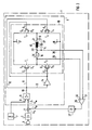
- Figure 1 shows a hearing aid 1 with an amplifier 2, which is fed by a microphone 3 with audible signals and is connected via a summing element 4 to an input 5 of a push-pull output stage 6 (switching amplifier).
- a generator 7 generates an ultrasonic frequency, which acts in the form of a symmetrical triangular voltage on a further input 8 of the output stage 6.
- the output stage 6 has a comparator 9 on the input side.
- the comparator 9 forms a rectangular signal in the ultrasonic frequency range corresponding to the ultrasonic frequency of the generator 7 from the two input signals (audible sound and ultrasound).
- the rectangular signal has pulses of different duration.
- the different duration of the individual pulses results on the one hand from the instantaneous value of the amplitude of the audible signal at input 5 and on the other hand from the variable (triangular) threshold voltage of the ultrasound signal at input 8 of comparator 9
- Comparator 9 a square wave signal available, in which the duration of the individual pulses is dependent on the audible sound signal, according to a known pulse duration modulation.
- the output 10 of the comparator 9 is connected via a line 11 to the gate terminal G1 of the transistor T1 and via a line 12 to the gate terminal G4 of the transistor T4 connected. Furthermore, the output 10 of the comparator 9 is connected via a line 13 to an inverter 14, in which the square wave signal for controlling (for switching) the complementary transistors T2 and T3 is inverted. Consequently, the transistors T2 and T3 are switched via their gate connections G2 and G3 with a complementary square wave signal.
- the transistors T1 to T4 are arranged in a bridge circuit in this embodiment, a receiver 15 or its coil 16 being part of a bridge branch between the transistors T1 / T2 and T3 / T4.
- the bridge circuit is connected via the positive operating voltage connection 17 and the negative operating voltage connection 18 to a current source, for example to a hearing aid battery (not shown).
- the arranged as a bridge circuit transistors T1 to T4 and the receiver 15 are also part of an output circuit 19 of the output stage 6.
- the output stage 6 works in push-pull.
- the transistors T2 and T3 or the transistors T1 and T4 are simultaneously conductive.
- the effect of the handset impedance is initially not taken into account. Consequently (to put it simply), the current flows in the output circuit 19 during a first switching state, for example, starting from the operating voltage connection 17, via a source connection S3 and a drain connection D3 of the switched transistor T3, then via the coil 16 of the receiver 15 and via the drain connection D2 and the source terminal S2 of the conductive transistor T2 to the operating voltage terminal 18.
- the transistors T2 and T4 are turned on, the current flows from the operating voltage terminal 17 via a source terminal S1 and a drain terminal D1 of the transistor T1, in opposite directions Direction via the receiver coil 16 to a drain terminal D4 and a source terminal S4 of the transistor T4 to the negative operating voltage terminal 18th
- the receiver 15 does not represent a purely ohmic resistance for the current changing with an ultrasound frequency, but is a frequency-dependent resistance (an impedance).
- the receiver 15 therefore also acts as a power store.
- the storage effect is influenced by the duration of the individual pulses.
- a feedback path is provided to increase the impedance of the output circuit 19, which in this exemplary embodiment comprises lines 22 to 24, an electronic switch 25, a differential amplifier 26, a low-pass filter 27 and the summing element 4.
- the respectively switched transistors T1 to T4 each have so-called volume resistances (internal) in the conductive state. These volume resistances are shown in Figure 1 at the source terminals S1 and S2 by dashed resistance symbols 28 and 29. The volume resistance 28 appears when T1 is conductive and the volume resistance 29 appears when T2 is conductive.
- the volume resistances 28 and 29 are used as decoupling means, via which an electrical signal dependent on the switching state of the receiver 15 can be extracted.
- the drawn in Figure 1 Volume resistors 28 and 29 are not physically present as a separate component, but appear alternately within the transistors T 1 and T 2 whenever the semiconductors T 1 and T 2 are switched in phase opposition with the ultrasound frequency. Consequently, the electrical signal dependent on the switching state of the receiver 15 can be extracted via the transistor T 1 by means of the lines 23 and 24 and via the transistor T 2 by means of the lines 22 and 23.
- the electronic switch 25 has an input pole 39 which is connected to the line 22 of the one feedback path. Another input pole 40 of the switch 25 is connected to the line 24 of the other feedback path.
- An output pole 30 on the switch 25 is connected to an input 31 of the differential amplifier 26.
- Another input 32 on the differential amplifier 26 is connected to the further (common) line 23 of the aforementioned feedback paths.
- the electronic switch 25 is connected to the output 10 of the comparator 9 via a switch control 33. Consequently, the switch 25 is controlled by a switching signal which is dependent on the ultrasound frequency.
- the electrical signals taken from the two decoupling means 28 and 29 and dependent on the switching state of the receiver 15 can act in phase on the output stage 6 to increase the impedance of the output circuit 19.
- FIG. 2 Another special embodiment is shown in Figure 2.
- essentially only the feedback path and the decoupling means are different from the exemplary embodiment according to FIG.
- a resistor 34 is used as the decoupling means according to FIG.
- the resistor 34 is connected in series with the receiver 15 within a bridge branch between the transistors T1 / T2 and T3 / T4. Consequently, a voltage drop arises at the one resistor 34 in each switching state of the receiver, which is conducted as an electrical signal dependent on the switching state of the receiver via lines 35 and 36 to the inputs 32 and 31 of the differential amplifier 26.
- the special arrangement of the decoupling resistor 34 in the bridge branch of the output circuit 19 advantageously eliminates the switching device shown in FIG. 1, which includes the switch 25 and the switch control 33.
- the low-pass filter 27 can have a cut-off frequency of 10 kHz, so that sound frequencies (audible sound) are let through and the ultrasound frequency which switches over the output stage 6 is blocked. With a corresponding design of the output stage 6 or the output circuit 19 with a filter blocking the ultrasound frequency and suitable coupling of the feedback path, the low-pass filter 27 in the feedback path can also be omitted.
- the impedance of the output circuit 19 can be increased to such an extent that different ones
- the receiver 15 can be adapted with the aid of a capacitor 37 to the push-pull output stage 6 of the hearing device 1 operating in the switching mode and the frequency response of the receiver 15 used in each case can be influenced by a capacitor 37 connected in parallel therewith.
- the design of the hearing device according to the invention results in a higher quality of the output circuit, as a result of which an increase (resonance) occurs in the frequency response of the output circuit, which can be adjusted with the capacitor 37.
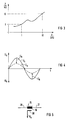
- FIG. 3 shows the impedance curve of a receiver 15, which can differ depending on the receiver type.
- the impedance of the receiver 15 is approximately 1 kOhm at 1 kHz and approximately 10 kOhm at 10 kHz.
- the continuous curve U S shows the audible sound signal which is present at the output of the amplifier 2 and at an input of the summing element 4 according to FIG. 2 connected to it.
- the curve U in shown in dashed lines in FIG. 4 represents a voltage which is present in FIG. 2 at the input 5 of the comparator circuit 9 as voltage U in .
- the difference between the two voltages U S and U in results from the signal -U R or + U R , which is dependent on the switching state of the receiver; compare the two corresponding arrows in FIG. 4.
- the voltage U R is likewise fed to an input of the summing element 4 and was generated from the voltage drop i R across the resistor 34 via the differential amplifier 26.
- the current i R is proportional to the listener current i H.
- the receiver current i H decreases with increasing impedance of the receiver 15.
- the voltage U R also decreases.
- less is subtracted from the voltage U S in the summing element 4, so that the voltage U in at the input 5 of the comparator 9 is greater as a result.
- the push-pull output stage 6 was operated as a bridge circuit in an output circuit 19.
- the power amplifier can e.g. have only two transistors, which is fed via a receiver with center tap.
- FIG. 5 shows a further receiver 15 with a coil 16 and the connections 20 and 21, which can be arranged in the bridge branch of the output circuit 19 according to FIGS. 1 and 2.
- a probe 38 is inductively coupled to the coil 16 of the receiver 15 in FIG.
- the probe 38 can be accommodated in the associated housing (not shown) of the receiver 15.
- the probe 38 can also be designed as a secondary winding of the coil 16.
- the feedback voltage U R can be fed to the differential amplifier 26 with one pole (as shown) or two poles.
Abstract
Description
Die Erfindung betrifft ein Hörgerät mit einem Verstärker und mit einer Gegentaktendstufe, die im Schaltbetrieb arbeitet und einen Hörer in einem Ausgangskreis in zeitlicher Abhängigkeit von einem Hörschallsignal mit einer Ultraschallfrequenz schaltet.The invention relates to a hearing aid with an amplifier and with a push-pull output stage, which operates in switching mode and switches an earphone in an output circuit as a function of time of an audible sound signal with an ultrasound frequency.
Aus der DE-PS 36 16 752 ist ein Hörgerät der eingangs genannten Art bekannt. Bei dem bekannten Hörgerät ist die im Schaltbetrieb arbeitende Gegentaktendstufe mit CMOS-Transistoren als Klasse D-Verstärker ausgebildet, in dessen Ausgangskreis ein Hörer angeordnet ist. Zu diesem Hörer ist ein Kondensator parallelgeschaltet. Zu der bekannten Parallelschaltung aus Kondensator und Hörer ist eine Induktivität in Reihe geschaltet. Die Induktivität und der Kondensator wirken im Ausgangskreis der als Brückenschaltung arbeitenden Gegentaktendstufe als Filter, das die im Ultraschallbereich liegende Schaltfrequenz unterdrücken soll. Die Schaltfrequenz kann z.B. 40 oder 100 kHz betragen.From DE-PS 36 16 752 a hearing aid of the type mentioned is known. In the known hearing aid, the push-pull output stage, which operates in switching operation, is designed with CMOS transistors as a class D amplifier, in the output circuit of which a receiver is arranged. A capacitor is connected in parallel with this receiver. An inductance is connected in series with the known parallel connection of capacitor and receiver. The inductance and the capacitor act in the output circuit of the push-pull output stage, which works as a bridge circuit, as a filter which is intended to suppress the switching frequency in the ultrasound range. The switching frequency can e.g. 40 or 100 kHz.
Der Ausgangskreis des bekannten Schaltverstärkers (Gegentaktendstufe) weist stets eine relativ niedrige Impedanz auf, unter anderem wegen der niederohmig wirkenden CMOS-Transistoren (CMOS-Schalter). Wenn mit einem elektrisch parallel zum Hörer angeordneten Kondensator auch der Frequenzgang des Hörers (Tonfrequenzen ca. 1 bis 6 kHz) beeinflußt und/oder an die Endstufe angepaßt werden soll, müßte wegen der Niederohmigkeit des Ausgangskreises ein Kondensator mit sehr großer Kapazität verwendet werden. Ein derartiger Kondensator würde aber die Güte des Ausgangskreises des Schaltverstärkers erheblich vermindern. Daher kann keine Resonanzstelle in dem Frequenzgang des bekannten Schaltverstärkers auftreten. Folglich ist in bekannten Schaltverstärkern keine Beeinflussung des Frequenzganges des Hörers (Tonfrequenz-/ Sprachfrequenzbereich) durch einen dazu parallelgeschalteten Kondensator möglich. Eine derartige, mit einem Kondensator einstellbare Resonanzstelle ist aber zur Anpassung des Frequenzganges des jeweils verwendeten Hörers an den Schaltverstärker wünschenswert und bei nicht im Schaltbetrieb arbeitenden Endstufen auch üblich.The output circuit of the known switching amplifier (push-pull output stage) always has a relatively low impedance, among other things because of the low-resistance CMOS transistors (CMOS switches). If the frequency response of the listener (tone frequencies approx. 1 to 6 kHz) is also to be influenced and / or adapted to the output stage with a capacitor arranged in parallel with the listener, a capacitor with a very large capacitance would have to be used because of the low impedance of the output circuit. However, such a capacitor would significantly reduce the quality of the output circuit of the switching amplifier. Therefore, no resonance point in the frequency response of the known Switching amplifier occur. Consequently, in known switching amplifiers it is not possible to influence the frequency response of the receiver (audio frequency / speech frequency range) by a capacitor connected in parallel with it. Such a resonance point, which can be set with a capacitor, is, however, desirable for adapting the frequency response of the receiver used in each case to the switching amplifier and is also customary for output stages which do not operate in switching mode.
Aufgabe der Erfindung ist es, bei einem Hörgerät der eingangs genannten Art den Schaltverstärker so auszubilden, daß eine Beeinflussung des Frequenzganges des angeschlossenen Hörers durch einen dazu parallelgeschalteten Kondensator möglich wird.The object of the invention is to design the switching amplifier in a hearing device of the type mentioned in such a way that the frequency response of the connected receiver can be influenced by a capacitor connected in parallel with it.
Diese Aufgabe wird erfindungsgemäß durch die im Hauptanspruch genannten Merkmale gelöst. Dadurch lassen sich Hörer (unterschiedliche Hörertypen) mit verschiedenen Impedanzverläufen (Frequenzgängen) auch an im Schaltbetrieb arbeitende Gegentaktendstufen anpassen, was z.B. durch einen parallel zum Hörer geschalteten Kondensator geschehen kann.This object is achieved by the features mentioned in the main claim. As a result, listeners (different types of listeners) with different impedance profiles (frequency responses) can also be adapted to push-pull output stages, which e.g. can be done by a capacitor connected in parallel to the listener.
Weitere Vorteile und Einzelheiten der Erfindung ergeben sich aus der nachfolgenden Beschreibung von Ausführungsbeispielen anhand der Zeichnungen und in Verbindung mit den Ansprüchen.Further advantages and details of the invention emerge from the following description of exemplary embodiments with reference to the drawings and in conjunction with the claims.
Es zeigen:
- Figur 1 ein Hörgerät in symbolischer Darstellung mit einigen für die Erfindung wesentlichen prinzipiellen Schaltungsanordnungen;
Figur 2 ein Hörgerät gemäß Figur 1 mit einer Variante eines Rückkopplungsweges;Figur 3 einen Impedanzverlauf eines an den Schaltverstärker anzupassenden Hörers;- Figur 4 eine Darstellung der Amplitudenbeeinflussung eines Eingangssignales (Hörschall) durch das erfindungsgemäße Hörgerät gemäß
Figur 2 und - Figur 5 einen Hörer mit einem speziellen Auskoppelmittel in symbolischer Darstellung.
- Figure 1 shows a hearing aid in a symbolic representation with some essential circuit arrangements essential to the invention;
- Figure 2 shows a hearing aid according to Figure 1 with a variant of a feedback path;
- FIG. 3 shows an impedance curve of a receiver to be adapted to the switching amplifier;
- FIG. 4 shows a representation of the amplitude influence of an input signal (hearing sound) by the hearing device according to the invention according to FIGS. 2 and
- Figure 5 shows a handset with a special coupling means in a symbolic representation.
Figur 1 zeigt ein Hörgerät 1 mit einem Verstärker 2, der von einem Mikrofon 3 mit Hörschallsignalen gespeist wird und über ein Summierglied 4 mit einem Eingang 5 einer Gegentaktendstufe 6 (Schaltverstärker) verbunden ist. Ein Generator 7 erzeugt eine Ultraschallfrequenz, die in Form einer symmetrischen Dreieckspannung auf einen weiteren Eingang 8 der Endstufe 6 einwirkt. Die Endstufe 6 weist in diesem Ausführungsbeispiel eingangsseitig einen Komparator 9 auf. Der Komparator 9 formt aus den beiden Eingangssignalen (Hörschall und Ultraschall) ein Rechtecksignal im Ultraschallfrequenzbereich entsprechend der Ultraschallfrequenz des Generators 7. Das Rechtecksignal weist Impulse unterschiedlicher Zeitdauer auf. Die unterschiedliche Zeitdauer der einzelnen Impulse ergibt sich gemäß der bekannten Wirkungsweise eines Komparators einerseits aus dem Momentanwert der Amplitude des Hörschallsignales am Eingang 5 und andererseits aus der variablen (dreieckförmigen) Schwellenspannung des Ultraschallsignals am Eingang 8 des Komparators 9. Folglich steht an einem Ausgang 10 des Komparators 9 ein Rechtecksignal zur Verfügung, bei dem die Dauer der Einzelimpulse von dem Hörschallsignal abhängig ist, entsprechend einer bekannten Pulsdauermodulation.Figure 1 shows a hearing aid 1 with an
Mit dem am Ausgang 10 des Komparators 9 zur Verfügung stehenden Rechtecksignal werden Halbleiter geschaltet, die in diesem Ausführungsbeispiel als komplementäre CMOS-Transistoren T₁ bis T₄ ausgebildet sind. Zu diesem Zweck ist der Ausgang 10 des Komparators 9 über eine Leitung 11 mit dem Gate-Anschluß G₁ des Transistors T₁ und über eine Leitung 12 mit dem Gate-Anschluß G₄ des Transistors T₄ verbunden. Des weiteren ist der Ausgang 10 des Komparators 9 über eine Leitung 13 mit einem Inverter 14 verbunden, in welchem das Rechtecksignal zur Steuerung (zum Schalten) der Komplementärtransistoren T₂ und T₃ invertiert wird. Folglich werden die Transistoren T₂ und T₃ über deren Gate-Anschlüsse G₂ bzw. G₃ mit einem komplementären Rechtecksignal geschaltet. Die Transistoren T₁ bis T₄ sind in diesem Ausführungsbeispiel in einer Brückenschaltung angeordnet, wobei ein Hörer 15 bzw. dessen Spule 16 Bestandteil eines Brückenzweiges zwischen den Transistoren T₁/T₂ und T₃/T₄ ist. Die Brückenschaltung wird über den positiven Betriebsspannungsanschluß 17 und den negativen Betriebsspannungsanschluß 18 mit einer Stromquelle, z.B. mit einer nicht dargestellten Hörgerätebatterie, verbunden.With the square wave signal available at the
Die als Brückenschaltung angeordneten Transistoren T₁ bis T₄ und der Hörer 15 sind zugleich Bestandteil eines Ausgangskreises 19 der Endstufe 6. Die Endstufe 6 arbeitet im Gegentakt. Dabei sind die Transistoren T₂ und T₃ oder die Transistoren T₁ und T₄ gleichzeitig leitend. Zur Beschreibung des Stromflusses wird zur Vereinfachung die Wirkung der Hörerimpedanz zunächst nicht berücksichtigt. Folglich fließt (vereinfacht ausgedrückt) der Strom im Ausgangskreis 19 während eines ersten Schaltzustandes, z.B. ausgehend von dem Betriebsspannungsanschluß 17, über einen Sourceanschluß S₃ und einen Drainanschluß D₃ des leitend geschalteten Transistors T₃, sodann über die Spule 16 des Hörers 15 und über den Drainanschluß D₂ und den Sourceanschluß S₂ des leitend geschalteten Transistors T₂ zu dem Betriebsspannungsanschluß 18. Wenn dagegen im anderen Fall die Transistoren T₂ und T₄ leitend geschaltet sind, fließt der Strom ausgehend von dem Betriebsspannungsanschluß 17 über einen Sourceanschluß S₁ und einen Drainanschluß D₁ des Transistors T₁, in entgegengesetzter Richtung über die Hörerspule 16 zu einem Drainanschluß D₄ und einem Sourceanschluß S₄ des Transistors T₄ zu dem negativen Betriebsspannungsanschluß 18.The arranged as a bridge circuit transistors T₁ to T₄ and the
Der wahre Stromfluß ist aber erheblich komplexer, weil der Hörer 15 für den mit einer Ultraschallfrequenz wechselnden Strom keinen rein ohmschen Widerstand darstellt, sondern ein frequenzabhängiger Widerstand (eine Impedanz) ist. Der Hörer 15 wirkt daher auch als Stromspeicher. Die Speicherwirkung wird von der Dauer der Einzelimpulse beeinflußt. Man kann daher auch davon sprechen, daß der Hörer 15 im Ausgangskreis 19 der Endstufe 6 durch die mit einer Ultraschallfrequenz gesteuerten Transistoren T₁ bis T₄ mit der Häufigkeit der vom Generator 7 abgegebenen Ultraschallfrequenz und in zeitlicher Abhängigkeit von der Amplitude des Hörschallsignals am Eingang 5 des Komparators 9 umgepolt wird. Folglich wechselt die an den beiden Anschlüssen 20 und 21 des Hörers 15 über die Transistoren T₁ bis T₄ angeschaltete Spannung ihre Polarität entsprechend der Schaltfrequenz und entsprechend der Dauer der einzelnen Impulse. Durch diesen Schaltbetrieb entstehen die eingangs geschilderten Nachteile in dem Ausgangskreis 19.However, the true current flow is considerably more complex because the
Erfindungsgemäß ist zur Erhöhung der Impedanz des Ausgangskreises 19 ein Rückkopplungsweg vorgesehen, der in diesem Ausführungsbeispiel Leitungen 22 bis 24, einen elektronischen Schalter 25, einen Differenzverstärker 26, einen Tiefpaßfilter 27 und das Summierglied 4 umfaßt. Die jeweils leitend geschalteten Transistoren T₁ bis T₄ weisen in dem leitenden Zustand jeweils sogenannte Durchgangswiderstände (intern) auf. Diese Durchgangswiderstände sind in der Figur 1 an den Sourceanschlüssen S₁ und S₂ durch strichliert gezeichnete Widerstandssymbole 28 und 29 dargestellt. Der Durchgangswiderstand 28 erscheint, wenn T₁ leitend ist und der Durchgangswiderstand 29 erscheint, wenn T₂ leitend ist.According to the invention, a feedback path is provided to increase the impedance of the
Gemäß einem Ausführungsbeispiel der Erfindung werden die Durchgangswiderstände 28 und 29 als Auskoppelmittel verwendet, über welche ein von dem Schaltzustand des Hörers 15 abhängiges elektrisches Signal entnehmbar ist. Die in Figur 1 gezeichneten Durchgangswiderstände 28 und 29 sind körperlich nicht als separates Bauteil vorhanden, sondern erscheinen innerhalb der Transistoren T₁ bzw. T₂ wechselweise immer dann, wenn die Halbleiter T₁ bzw. T₂ mit der Ultraschallfrequenz gegenphasig leitend geschaltet werden. Folglich kann über den Transistor T₁ mittels der Leitungen 23 und 24 sowie über den Transistor T₂ mittels der Leitungen 22 und 23 das vom Schaltzustand des Hörers 15 abhängige elektrische Signal entnommen werden. Der elektronische Schalter 25 weist einen Eingangspol 39 auf, der mit der Leitung 22 des einen Rückkopplungsweges verbunden ist. Ein weiterer Eingangspol 40 des Schalters 25 ist mit der Leitung 24 des anderen Rückkopplungsweges verbunden. Ein Ausgangspol 30 am Schalter 25 ist mit einem Eingang 31 des Differenzverstärkers 26 verbunden. Ein anderer Eingang 32 am Differenzverstärker 26 ist mit der weiteren (gemeinsamen) Leitung 23 der zuvor genannten Rückkopplungswege verbunden. Der elektronische Schalter 25 ist in diesem Ausführungsbeispiel über eine Schaltersteuerung 33 mit dem Ausgang 10 des Komparators 9 verbunden. Folglich wird der Schalter 25 von einem von der Ultraschallfrequenz abhängigen Schaltsignal gesteuert. Damit können die aus beiden Auskoppelmitteln 28 und 29 entnommenen und vom Schaltzustand des Hörers 15 abhängigen elektrischen Signale phasenrichtig auf die Endstufe 6 zur Erhöhung der Impedanz des Ausgangskreises 19 einwirken.According to an embodiment of the invention, the
Wesentliche Vorteile dieses speziellen erfindungsgemäßen Ausführungsbeispieles bestehen darin, daß als Auskoppelmittel in der Endstufe 6 für einen anderen Zweck erforderliche Bauteile (Transistoren) verwendet werden. Daher wird kein zusätzliches Bauteil als Auskoppelmittel benötigt. Da die Durchgangswiderstände 28 und 29 ohmschen Charakter haben und im übrigen mit dem Hörer 15 eine Reihenschaltung bilden, ist über diese Auskoppelmittel 28 und 29 ohne weiteres eine dem Hörerstrom proportionale Spannung als Rückkopplungssignal entnehmbar. Ganz wesentlich ist dabei auch, daß durch den Fortfall von zusätzlichen (separaten) Auskoppelmitteln im Ausgangskreis 19 der Endstufe 6 kein zusätzlicher Spannungsabfall entstehen kann, der den Wirkungsgrad bzw. die Ausgangsleistung der Endstufe 6 vermindern würde. Bei derartigen Hörgeräten wirken sich nämlich schon kleinste Spannungsabfälle störend aus, da die Hörgeräte im allgemeinen mit Betriebsspannungen von nur ca. 1,3 V betrieben werden.Significant advantages of this special exemplary embodiment according to the invention are that components (transistors) required for another purpose are used as decoupling means in the
Ein weiteres spezielles Ausführungsbeispiel ist in Figur 2 dargestellt. In diesem Ausführungsbeispiel sind im wesentlichen nur der Rückkopplungsweg und das Auskoppelmittel gegenüber dem Ausführungsbeispiel gemäß Figur 1 anders ausgebildet. Als Auskoppelmittel wird gemäß Figur 2 ein Widerstand 34 verwendet. Der Widerstand 34 ist innerhalb eines Brückenzweiges zwischen den Transistoren T₁/T₂ und T₃/T₄ mit dem Hörer 15 in Reihe geschaltet. Folglich entsteht an dem einen Widerstand 34 in jedem Schaltzustand des Hörers ein Spannungsabfall, der als ein von dem Schaltzustand des Hörers abhängiges elektrisches Signal über Leitungen 35 und 36 zu den Eingängen 32 und 31 des Differenzverstärkers 26 geführt wird. Durch die spezielle Anordnung des Auskoppelwiderstandes 34 im Brückenzweig des Ausgangskreises 19 entfällt in vorteilhafter Weise die in Figur 1 dargestellte Umschalteinrichtung, die den Schalter 25 und die Schaltersteuerung 33 umfaßt. Das Tiefpaßfilter 27 kann eine Grenzfrequenz von 10 kHz aufweisen, so daß Tonfrequenzen (Hörschall) durchgelassen und die die Endstufe 6 umschaltende Ultraschallfrequenz gesperrt wird. Bei entsprechender Auslegung der Endstufe 6 bzw. des Ausgangskreises 19 mit einem die Ultraschallfrequenz sperrenden Filter und geeigneter Ankopplung des Rückkopplungsweges kann das Tiefpaßfilter 27 im Rückkopplungsweg auch entfallen.Another special embodiment is shown in Figure 2. In this exemplary embodiment, essentially only the feedback path and the decoupling means are different from the exemplary embodiment according to FIG. A
Mit den beiden anhand der Figuren 1 und 2 beschriebenen Varianten eines Hörgerätes 1 gemäß der Erfindung läßt sich die Impedanz des Ausgangskreises 19 so weit erhöhen, daß unterschiedliche Hörer 15 mit Hilfe eines Kondensators 37 an die im Schaltbetrieb arbeitende Gegentaktendstufe 6 des Hörgerätes 1 anpaßbar und der Frequenzgang des jeweils verwendeten Hörers 15 durch einen dazu parallelgeschalteten Kondensator 37 beeinflußbar ist. Insbesondere entsteht durch die erfindungsgemäße Ausbildung des Hörgerätes eine höhere Güte des Ausgangskreises, durch die eine Überhöhung (Resonanz) im Frequenzgang des Ausgangskreises auftritt, die mit dem Kondensator 37 einstellbar ist.With the two variants of a hearing aid 1 according to the invention described with reference to FIGS. 1 and 2, the impedance of the
Die Wirkungsweise der Rückkopplung bei einem erfindungsgemäßen Hörgerät wird anhand der Figur 2 in Verbindung mit den Figuren 3 und 4 kurz (vereinfacht) beschrieben. Figur 3 zeigt den Impedanzverlauf eines Hörers 15, der je nach Hörertyp verschieden sein kann. Die Impedanz des Hörers 15 beträgt im vorliegenden Beispiel gemäß Figur 3 bei 1 kHz etwa 1 kOhm und bei 10 kHz etwa 10 kOhm. In Figur 4 ist mit der durchgehenden Kurve US das Hörschallsignal dargestellt, das am Ausgang des Verstärkers 2 sowie an einem damit verbundenen Eingang des Summiergliedes 4 gemäß Figur 2 anliegt. Die in Figur 4 strichliert gezeichnete Kurve Uin stellt eine Spannung dar, die in Figur 2 am Eingang 5 der Komparatorschaltung 9 als Spannung Uin anliegt. Die Differenz zwischen den beiden Spannungen US und Uin ergibt sich aus dem vom Schaltzustand des Hörers abhängigen Signal -UR bzw. +UR; vergleiche die beiden entsprechenden Pfeile in Figur 4. In Figur 2 wird die Spannung UR ebenfalls einem Eingang des Summiergliedes 4 zugeführt und wurde aus einem Spannungsabfall iR am Widerstand 34 über den Differenzverstärker 26 erzeugt. Der Strom iR ist proportional zu dem Hörerstrom iH. Der Hörerstrom iH nimmt mit zunehmender Impedanz des Hörers 15 ab. Folglich wird auch die Spannung UR kleiner. Dadurch wird im Summierglied 4 weniger von der Spannung US subtrahiert, so daß im Ergebnis die Spannung Uin am Eingang 5 des Komparators 9 größer wird. Daraus folgt eine längere Impulsdauer am Ausgang 10 des Komparators 9. Das führt wiederum zu einer längeren Durchschaltdauer der Transistoren (Schalter), z.B. T₁ und T₄. Sonach entsteht im Brückenzweig des Ausgangskreises 19 eine längere Integrationszeit des Hörerstromes iH und des Stromes iR, was einer Stromerhöhung gleichkommt. Das ursprüngliche Absinken von iR ist dadurch weitgehend ausgeglichen worden.The mode of operation of the feedback in a hearing aid according to the invention is briefly (simplified) described with reference to FIG. 2 in conjunction with FIGS. 3 and 4. FIG. 3 shows the impedance curve of a
In den beiden beschriebenen Ausführungsbeispielen gemäß den Figuren 1 und 2 wurde die Gegentaktendstufe 6 als Brückenschaltung in einem Ausgangskreis 19 betrieben. Es ist aber auch möglich, bei einem erfindungsgemäßen Hörgerät die Gegentaktendstufe nicht in Brückenschaltung zu betreiben. So kann die Endstufe z.B. nur zwei Transistoren aufweisen, die über einen Hörer mit Mittenanzapfung gespeist wird.In the two described exemplary embodiments according to FIGS. 1 and 2, the push-
Figur 5 zeigt einen weiteren Hörer 15 mit einer Spule 16 sowie den Anschlüssen 20 und 21, der gemäß Figur 1 bzw. 2 in dem Brückenzweig des Ausgangskreises 19 angeordnet sein kann. Nach einer weiteren Variante der Erfindung ist in Figur 5 als Auskoppelmittel eine Sonde 38 induktiv mit der Spule 16 des Hörers 15 gekoppelt. Die Sonde 38 kann in dem zugehörigen Gehäuse (nicht dargestellt) des Hörers 15 untergebracht sein. Die Sonde 38 kann dabei auch als Sekundärwicklung der Spule 16 ausgebildet werden. Die Rückkopplungsspannung UR kann einpolig (wie dargestellt) oder zweipolig zum Differenzverstärker 26 geführt werden.FIG. 5 shows a
Claims (10)
- Hearing aid with an amplifier (2) and with a push-pull output stage (6) which operates in switching operation and connects an earphone (15) in an output circuit (19) in temporal dependence upon an audible sound signal with an ultrasonic frequency, whereby the output stage has at least one decoupling means (28, 29; 34; 38), by way of which an electrical signal (UR) dependent on the switching state of the earphone (15) can be removed, which acts by way of at least one feedback path (22 to 27; 35, 36, 26, 27) on the output stage (6) to increase the impedance of the output circuit (19).
- Hearing aid according to claim 1, whereby the decoupling means (34) forms a series connection with the earphone (15).
- Hearing aid according to claim 1 or 2, whereby the signal (UR) decoupled from the decoupling means (28, 29; 34; 38) is a voltage proportional to the earphone current.
- Hearing aid according to one of claims 1 to 3, whereby the decoupling means is a resistor (28, 29; 34) arranged in the output circuit (19).
- Hearing aid according to one of claims 1 to 4, whereby a component (T₁, T₂) present in the output stage (6) is also used as decoupling means.
- Hearing aid according to one of claims 1 to 5, whereby that respective volume resistance (28, 29) is used as decoupling means which appears alternately at two semiconductor components (T₁, T₂) of the output stage (6) which are connected to the ultrasonic frequency in a conducting manner in phase opposition to the ultrasonic frequency.
- Hearing aid according to claim 6, whereby of each of the two semiconductor components (T₁, T₂) at least one line (22, 23, 24) of the respective feedback path (22 to 27) is guided to a respective input pole (39, 40) of an electronic changeover switch (25), whereby the changeover switch (25) is controlled by a switching signal dependent on the ultrasonic frequency and is connected by way of an output pole (30) to an input (31) of a difference amplifier (26) in the feedback path.
- Hearing aid according to one of claims 1 to 7, whereby the signal removed by way of the decoupling means (28, 29; 34; 38) is supplied to a summation element (4) which is connected to an input (5) of the output stage (6) operating in switching operation.
- Hearing aid according to one of claims 1 to 3, whereby the decoupling means are constructed as means (38) acting in an inductive manner.
- Hearing aid according to one of claims 1 to 3, whereby the decoupling means are constructed as a probe (38) coupled to the coil (16) of the earphone (15).
Priority Applications (5)
| Application Number | Priority Date | Filing Date | Title |
|---|---|---|---|
| DE59104497T DE59104497D1 (en) | 1991-03-21 | 1991-03-21 | Hearing aid with a power amplifier operating in switching mode. |
| EP91104449A EP0504460B1 (en) | 1991-03-21 | 1991-03-21 | Hearing aid with a switching amplifier output stage |
| AT91104449T ATE118132T1 (en) | 1991-03-21 | 1991-03-21 | HEARING AID WITH A POWER STAMP THAT WORKS IN SWITCHING OPERATION. |
| DK91104449.3T DK0504460T3 (en) | 1991-03-21 | 1991-03-21 | Hearing aid with an output stage working in clutch mode |
| CA002063512A CA2063512A1 (en) | 1991-03-21 | 1992-03-19 | Hearing aid with an end stage that operates in switching mode |
Applications Claiming Priority (1)
| Application Number | Priority Date | Filing Date | Title |
|---|---|---|---|
| EP91104449A EP0504460B1 (en) | 1991-03-21 | 1991-03-21 | Hearing aid with a switching amplifier output stage |
Publications (2)
| Publication Number | Publication Date |
|---|---|
| EP0504460A1 EP0504460A1 (en) | 1992-09-23 |
| EP0504460B1 true EP0504460B1 (en) | 1995-02-01 |
Family
ID=8206553
Family Applications (1)
| Application Number | Title | Priority Date | Filing Date |
|---|---|---|---|
| EP91104449A Expired - Lifetime EP0504460B1 (en) | 1991-03-21 | 1991-03-21 | Hearing aid with a switching amplifier output stage |
Country Status (5)
| Country | Link |
|---|---|
| EP (1) | EP0504460B1 (en) |
| AT (1) | ATE118132T1 (en) |
| CA (1) | CA2063512A1 (en) |
| DE (1) | DE59104497D1 (en) |
| DK (1) | DK0504460T3 (en) |
Families Citing this family (2)
| Publication number | Priority date | Publication date | Assignee | Title |
|---|---|---|---|---|
| US5672998A (en) * | 1995-08-09 | 1997-09-30 | Harris Corporation | Class D amplifier and method |
| US5815581A (en) * | 1995-10-19 | 1998-09-29 | Mitel Semiconductor, Inc. | Class D hearing aid amplifier with feedback |
Family Cites Families (1)
| Publication number | Priority date | Publication date | Assignee | Title |
|---|---|---|---|---|
| US5014016A (en) * | 1989-04-13 | 1991-05-07 | Beltone Electronics Corporation | Switching amplifier |
-
1991
- 1991-03-21 AT AT91104449T patent/ATE118132T1/en not_active IP Right Cessation
- 1991-03-21 DE DE59104497T patent/DE59104497D1/en not_active Expired - Fee Related
- 1991-03-21 DK DK91104449.3T patent/DK0504460T3/en active
- 1991-03-21 EP EP91104449A patent/EP0504460B1/en not_active Expired - Lifetime
-
1992
- 1992-03-19 CA CA002063512A patent/CA2063512A1/en not_active Abandoned
Also Published As
| Publication number | Publication date |
|---|---|
| ATE118132T1 (en) | 1995-02-15 |
| DE59104497D1 (en) | 1995-03-16 |
| EP0504460A1 (en) | 1992-09-23 |
| DK0504460T3 (en) | 1995-07-10 |
| CA2063512A1 (en) | 1992-09-22 |
Similar Documents
| Publication | Publication Date | Title |
|---|---|---|
| DE3607492C2 (en) | Switching power amplifier | |
| EP0563421B1 (en) | Circuit arrangement with a switch amplifier | |
| EP0468072B1 (en) | Hearing aid comprising an output amplifier with a limiting circuit | |
| EP0098421B1 (en) | Electric hearing aid | |
| DE3213269A1 (en) | AMPLIFIER FOR PULSE WIDTH-MODULATED SIGNALS | |
| EP0753935B1 (en) | Signal amplifier | |
| DE19836997A1 (en) | Transmit/receive circuit based on ultrasound-transducer e.g. for examining continuity of materials interfaces | |
| EP0504460B1 (en) | Hearing aid with a switching amplifier output stage | |
| DE3138919A1 (en) | "BRIDGE AMPLIFIER WITH COMPLEMENTARY FIELD EFFECT TRANSISTORS" | |
| DE3103310C2 (en) | Low frequency amplifier with a feedback circuit to compensate for non-linearities in the speaker impedance | |
| DE3103346C2 (en) | Low frequency amplifier with a feedback circuit to compensate for non-linearities in loudspeaker impedance | |
| DE10248677A1 (en) | Evaluation and control circuit for sound transducer of vehicle parking aid, has two magnetically coupled transformers with their secondary windings electrically connected to terminals of transducer | |
| AT403978B (en) | SINGLE CHANNEL CIRCUIT FOR A HEARING AID | |
| DE3341570C2 (en) | ||
| EP1098436B1 (en) | Method for controlling an audio amplifier and audio amplifier with a switched output stage | |
| DE4303093C2 (en) | Condenser microphone consisting of two transducers with variable directional characteristics | |
| DE69909086T2 (en) | Circuit and its use to reduce distortion and interference from rectangular pulses | |
| DE3436284C2 (en) | ||
| DE2838038A1 (en) | Input circuit for telephone wire connection - has transistors, connected via collectors, to two wire and via transformer to four wire cable with supply to base and emitters | |
| DE1922382B2 (en) | ELECTRONIC COUPLING DEVICE WITH FIELD EFFECT TRANSISTORS | |
| DE102022118419A1 (en) | Tracking amplifier for inductive loads | |
| DE102022118432A1 (en) | Tracking amplifier for inductive loads | |
| DE2920079C2 (en) | Circuit arrangement for amplifying a low-frequency pulse-width-modulated square-wave signal | |
| DE10037373C1 (en) | Control method for electroacoustic transducer e.g. audio loudspeaker, has transducer coil electrodes coupled to same non-zero potential in rest phase | |
| DE3141420A1 (en) | Hearing aid |
Legal Events
| Date | Code | Title | Description |
|---|---|---|---|
| PUAI | Public reference made under article 153(3) epc to a published international application that has entered the european phase |
Free format text: ORIGINAL CODE: 0009012 |
|
| 17P | Request for examination filed |
Effective date: 19920128 |
|
| AK | Designated contracting states |
Kind code of ref document: A1 Designated state(s): AT CH DE DK FR GB IT LI NL |
|
| RAP1 | Party data changed (applicant data changed or rights of an application transferred) |
Owner name: SIEMENS AUDIOLOGISCHE TECHNIK GMBH |
|
| 17Q | First examination report despatched |
Effective date: 19940606 |
|
| GRAA | (expected) grant |
Free format text: ORIGINAL CODE: 0009210 |
|
| AK | Designated contracting states |
Kind code of ref document: B1 Designated state(s): AT CH DE DK FR GB LI NL |
|
| PG25 | Lapsed in a contracting state [announced via postgrant information from national office to epo] |
Ref country code: NL Effective date: 19950201 Ref country code: GB Effective date: 19950201 Ref country code: FR Effective date: 19950201 |
|
| REF | Corresponds to: |
Ref document number: 118132 Country of ref document: AT Date of ref document: 19950215 Kind code of ref document: T |
|
| REF | Corresponds to: |
Ref document number: 59104497 Country of ref document: DE Date of ref document: 19950316 |
|
| PG25 | Lapsed in a contracting state [announced via postgrant information from national office to epo] |
Ref country code: AT Effective date: 19950321 |
|
| PG25 | Lapsed in a contracting state [announced via postgrant information from national office to epo] |
Ref country code: LI Effective date: 19950331 Ref country code: CH Effective date: 19950331 |
|
| EN | Fr: translation not filed | ||
| REG | Reference to a national code |
Ref country code: DK Ref legal event code: T3 |
|
| NLV1 | Nl: lapsed or annulled due to failure to fulfill the requirements of art. 29p and 29m of the patents act | ||
| GBV | Gb: ep patent (uk) treated as always having been void in accordance with gb section 77(7)/1977 [no translation filed] |
Effective date: 19950201 |
|
| REG | Reference to a national code |
Ref country code: CH Ref legal event code: PL |
|
| PLBE | No opposition filed within time limit |
Free format text: ORIGINAL CODE: 0009261 |
|
| STAA | Information on the status of an ep patent application or granted ep patent |
Free format text: STATUS: NO OPPOSITION FILED WITHIN TIME LIMIT |
|
| 26N | No opposition filed | ||
| PGFP | Annual fee paid to national office [announced via postgrant information from national office to epo] |
Ref country code: DK Payment date: 19990309 Year of fee payment: 9 |
|
| PGFP | Annual fee paid to national office [announced via postgrant information from national office to epo] |
Ref country code: DE Payment date: 19990520 Year of fee payment: 9 |
|
| PG25 | Lapsed in a contracting state [announced via postgrant information from national office to epo] |
Ref country code: DK Free format text: LAPSE BECAUSE OF NON-PAYMENT OF DUE FEES Effective date: 20000321 |
|
| REG | Reference to a national code |
Ref country code: DK Ref legal event code: EBP |
|
| PG25 | Lapsed in a contracting state [announced via postgrant information from national office to epo] |
Ref country code: DE Free format text: LAPSE BECAUSE OF NON-PAYMENT OF DUE FEES Effective date: 20010103 |