EP0503554B1 - Molding method and apparatus - Google Patents
Molding method and apparatus Download PDFInfo
- Publication number
- EP0503554B1 EP0503554B1 EP92104058A EP92104058A EP0503554B1 EP 0503554 B1 EP0503554 B1 EP 0503554B1 EP 92104058 A EP92104058 A EP 92104058A EP 92104058 A EP92104058 A EP 92104058A EP 0503554 B1 EP0503554 B1 EP 0503554B1
- Authority
- EP
- European Patent Office
- Prior art keywords
- die
- shaping
- resinous material
- roll
- counter roll
- Prior art date
- Legal status (The legal status is an assumption and is not a legal conclusion. Google has not performed a legal analysis and makes no representation as to the accuracy of the status listed.)
- Expired - Lifetime
Links
Images





Classifications
-
- B—PERFORMING OPERATIONS; TRANSPORTING
- B29—WORKING OF PLASTICS; WORKING OF SUBSTANCES IN A PLASTIC STATE IN GENERAL
- B29C—SHAPING OR JOINING OF PLASTICS; SHAPING OF MATERIAL IN A PLASTIC STATE, NOT OTHERWISE PROVIDED FOR; AFTER-TREATMENT OF THE SHAPED PRODUCTS, e.g. REPAIRING
- B29C70/00—Shaping composites, i.e. plastics material comprising reinforcements, fillers or preformed parts, e.g. inserts
- B29C70/04—Shaping composites, i.e. plastics material comprising reinforcements, fillers or preformed parts, e.g. inserts comprising reinforcements only, e.g. self-reinforcing plastics
- B29C70/28—Shaping operations therefor
- B29C70/40—Shaping or impregnating by compression not applied
- B29C70/50—Shaping or impregnating by compression not applied for producing articles of indefinite length, e.g. prepregs, sheet moulding compounds [SMC] or cross moulding compounds [XMC]
- B29C70/504—Shaping or impregnating by compression not applied for producing articles of indefinite length, e.g. prepregs, sheet moulding compounds [SMC] or cross moulding compounds [XMC] using rollers or pressure bands
-
- B—PERFORMING OPERATIONS; TRANSPORTING
- B29—WORKING OF PLASTICS; WORKING OF SUBSTANCES IN A PLASTIC STATE IN GENERAL
- B29C—SHAPING OR JOINING OF PLASTICS; SHAPING OF MATERIAL IN A PLASTIC STATE, NOT OTHERWISE PROVIDED FOR; AFTER-TREATMENT OF THE SHAPED PRODUCTS, e.g. REPAIRING
- B29C43/00—Compression moulding, i.e. applying external pressure to flow the moulding material; Apparatus therefor
- B29C43/22—Compression moulding, i.e. applying external pressure to flow the moulding material; Apparatus therefor of articles of indefinite length
-
- B—PERFORMING OPERATIONS; TRANSPORTING
- B29—WORKING OF PLASTICS; WORKING OF SUBSTANCES IN A PLASTIC STATE IN GENERAL
- B29C—SHAPING OR JOINING OF PLASTICS; SHAPING OF MATERIAL IN A PLASTIC STATE, NOT OTHERWISE PROVIDED FOR; AFTER-TREATMENT OF THE SHAPED PRODUCTS, e.g. REPAIRING
- B29C70/00—Shaping composites, i.e. plastics material comprising reinforcements, fillers or preformed parts, e.g. inserts
- B29C70/04—Shaping composites, i.e. plastics material comprising reinforcements, fillers or preformed parts, e.g. inserts comprising reinforcements only, e.g. self-reinforcing plastics
- B29C70/06—Fibrous reinforcements only
- B29C70/10—Fibrous reinforcements only characterised by the structure of fibrous reinforcements, e.g. hollow fibres
- B29C70/12—Fibrous reinforcements only characterised by the structure of fibrous reinforcements, e.g. hollow fibres using fibres of short length, e.g. in the form of a mat
- B29C70/14—Fibrous reinforcements only characterised by the structure of fibrous reinforcements, e.g. hollow fibres using fibres of short length, e.g. in the form of a mat oriented
-
- D—TEXTILES; PAPER
- D04—BRAIDING; LACE-MAKING; KNITTING; TRIMMINGS; NON-WOVEN FABRICS
- D04H—MAKING TEXTILE FABRICS, e.g. FROM FIBRES OR FILAMENTARY MATERIAL; FABRICS MADE BY SUCH PROCESSES OR APPARATUS, e.g. FELTS, NON-WOVEN FABRICS; COTTON-WOOL; WADDING ; NON-WOVEN FABRICS FROM STAPLE FIBRES, FILAMENTS OR YARNS, BONDED WITH AT LEAST ONE WEB-LIKE MATERIAL DURING THEIR CONSOLIDATION
- D04H1/00—Non-woven fabrics formed wholly or mainly of staple fibres or like relatively short fibres
- D04H1/40—Non-woven fabrics formed wholly or mainly of staple fibres or like relatively short fibres from fleeces or layers composed of fibres without existing or potential cohesive properties
- D04H1/42—Non-woven fabrics formed wholly or mainly of staple fibres or like relatively short fibres from fleeces or layers composed of fibres without existing or potential cohesive properties characterised by the use of certain kinds of fibres insofar as this use has no preponderant influence on the consolidation of the fleece
- D04H1/4209—Inorganic fibres
- D04H1/4218—Glass fibres
-
- D—TEXTILES; PAPER
- D04—BRAIDING; LACE-MAKING; KNITTING; TRIMMINGS; NON-WOVEN FABRICS
- D04H—MAKING TEXTILE FABRICS, e.g. FROM FIBRES OR FILAMENTARY MATERIAL; FABRICS MADE BY SUCH PROCESSES OR APPARATUS, e.g. FELTS, NON-WOVEN FABRICS; COTTON-WOOL; WADDING ; NON-WOVEN FABRICS FROM STAPLE FIBRES, FILAMENTS OR YARNS, BONDED WITH AT LEAST ONE WEB-LIKE MATERIAL DURING THEIR CONSOLIDATION
- D04H1/00—Non-woven fabrics formed wholly or mainly of staple fibres or like relatively short fibres
- D04H1/40—Non-woven fabrics formed wholly or mainly of staple fibres or like relatively short fibres from fleeces or layers composed of fibres without existing or potential cohesive properties
- D04H1/42—Non-woven fabrics formed wholly or mainly of staple fibres or like relatively short fibres from fleeces or layers composed of fibres without existing or potential cohesive properties characterised by the use of certain kinds of fibres insofar as this use has no preponderant influence on the consolidation of the fleece
- D04H1/4209—Inorganic fibres
- D04H1/4218—Glass fibres
- D04H1/4226—Glass fibres characterised by the apparatus for manufacturing the glass fleece
Definitions
- the present invention generally relates to a method of and a device for molding and shaping fiber reinforced resinous material and, more particularly, to the method of and the device for molding and shaping a semi-cured molding material (either sheet molding compound or thick molding compound) comprising unsaturated polyester resin or epoxy resin mixed with a high temperature curing agent and reinforcement fibers such as, for example, glass fibers impregnated with said resin to provide a shaped article of manufacture of any desired shape wherein the reinforcement fibers are oriented in any desired direction.
- a semi-cured molding material either sheet molding compound or thick molding compound
- a compound consisting of reinforcement fibers such as glass fibers or carbon fibers, resin, and a curing agent into a required configuration.
- the reinforcement fibers, resin, and the curing agent are mixed with each other during the molding operation. That is, a wet material is used in this method.
- a prepreg sheet for example, a fiber reinforced resin such as sheet molding compound (SMC) or thick molding compound (TMC) consisting of the above described semi-cured reinforcement fibers, resin and the curing agent is used to mold the material by a press. That is, a dry material is used in this method.
- SMC sheet molding compound
- TMC thick molding compound
- the conventional molding method utilizing the dry material such as the sheet molding compound is superior and widely used because it does not cause environmental pollution unlike the method using the wet material; the sheet molding compound can be treated easily during the molding operation; and the surface of the resultant product is glossy.
- the material can be molded into the product having a complicated shape with high accurate dimensions.
- the dry molding of the compound such as the fiber reinforced resinous material is carried with a thermal compressive molding method in which a press and a mold are generally utilized.
- a press and a mold are generally utilized.
- an upper mold is pressed under a high pressure against the lower mold so that, within the cavity defined between the upper and lower molds, the compound can be shaped.
- this press molding is carried out at a high temperature and, during this press molding, a compound is also cured simultaneously.
- the high pressure of 1.2MPa is applied to the composite material at a time. Therefore, the composite material fluidizes abruptly with the consequence that the reinforcement fibers in the composite material are biased in an unexpected direction, making it impossible to control the orientation of the reinforcement fibers.
- the reinforcement fibers contained therein are not oriented in a particular direction and are substantially uniformly oriented in all direction. Therefore, the composite material is prepared having an isotropy in which the strength relative to any direction is uniform.
- the reinforcement fibers are oriented in the unexpected direction. Accordingly, for example, where the molded article is required to have an isotropic strength, the strength may vary depending on the direction making it impossible for the resultant article to satisfy the requirements.
- the molded article is required to have a so-called anisotropic strength in which the strength in one particular direction is higher than that in any other direction, it is difficult to control the reinforcement fibers to be oriented in the particular direction, thereby failing to satisfy the intended requirements.
- the composite material when the composite material is to be molded into a predetermined shape under the high pressure at a time through the press, the flow of the material varies from one place to another within the molding cavity of the press. Therefore, a peeling, a laminar separation, and an interlayer undulation tend to occur and, at the same time, the raw material will not be uniformly distributed, resulting in a defect in the eventually shaped products.
- the fiber reinforced resinous material such as the sheet molding compound is to be press-molded, a limitation in the mold design makes it difficult to mold the article of generally elongated configuration.
- the method utilizing the wet material has been widely used wherein, after the continuous reinforcement fibers have been impregnated with a resinous material, the reinforcement fibers are pulled from the cavity of the die by the application of a relatively great pulling force.
- the articles is to be continuously manufactured using the wet material as described above, the application of the relatively great pulling force results in an increased power consumption.
- the expensive continuous reinforcement fibers results in an increased manufacturing cost. While the plural reinforcement fibers are pulled into a bundle, the reinforcement fibers tend to be randomly aligned to deteriorate the physical properties of molded parts. Furthermore, it is to mold the article of relatively large size and complicated shape.
- British patent specification GB-A-759 902 discloses a process for the production of moulded articles, hollow bodies, pipes or plates, using liquid unsaturated polyester resins with liquid polymerisable ethylene derivatives, wherein these materials are fixed with filling material and tamped into moulds or formers.
- the final shaping may be done by a pressing or rolling method.
- French patent specification FR-A-1 455 038 discloses an apparatus having a shaping unit comprising a movable die, a counter roll, means for lowering said counter roll and driving means.
- An aspect of this object is to provide means for controlling the orientation of the reinforcement fibers.
- the orientation of the reinforcement fibers can be controlled during the molding operation so that one of anisotropic and isotropic strengths can be selected and, at the same time, a continuous molding with the use of the dry material is possible.
- small step processing is carried out in a superimposed fashion so that the fiber reinforced resinous material is stepwisely compressed at different stages to achieve a controlled orientation of the reinforcement fibers, which has hitherto been difficult in the press-molding operation, while eliminating any possible uneven fluidization.
- the die disposed in opposition to the roll referred to above may be either a flat mold or a generally cylindrical mold and, where a flat mold is employed, the roll may be supported for reciprocating motion over the flat die.
- both the roll and the cylindrical mold may be supported for rotation about their axes of rotation.
- the cylindrical mold may or may not have its outer peripheral surface formed with indentations.
- the cylindrical mold may have an outer peripheral surface of a shape substantially identical with the shape of the outer peripheral surface of the roll where the article desired to be manufactures is in the form of a plate having smooth surfaces opposite to each other.
- the fiber reinforced resinous material is compressed a plurality of times at a much lower pressure than the pressure required in the practice of the conventional method to apply until the fiber reinforced resinous material is compressed to the predetermined final degree of compression, which is preferably 70%.
- the extent to which the fiber reinforced resinous material is stepwisely compressed by the application of a single pressure and the number of times at which the compressive pressure is applied before the final degree of compression is attained, may be chosen according to the shape and the thickness of the eventually shaped article. However, the lower the pressure is applied at a time, the less the material is fluidized, rendering it difficult to orient the reinforcement fibers.
- the pressure applied to the fiber reinforced resinous material for each application of the pressure is preferably within the range of 1/5 to 1/100 of the final degree of compression which is defined as the extent to which the fiber reinforced resinous material is desired to be compacted to provide an intended article of manufacture.
- the speed at which the fiber reinforced resinous material is relatively moved between the roll and/or the die which are disposed in a plurality of stages spaced a distance from each other in the transport direction of the fiber reinforced resinous material may be uniform while all of the rolls employed have a uniform outer diameter and rotate at equal speed.
- the rolls may be driven at different speeds so that the speed at which the fiber reinforced resinous material is relatively moved between the roll and/or the die which are disposed in a plurality of spaced stages may vary in the direction of transport, or the use may be made of the rolls of varying outer diameters while the rolls are driven at an equal speed.
- the speed of transport of the fiber reinforced resinous material at a region upstream with respect to the direction of transport thereof is chosen to be lower than that at a region downstream with respect to the direction of transport, the reinforcement fibers contained in the fiber reinforced resinous material can be forced to orient in a direction parallel to the direction of transport so that the strength in a direction parallel to the direction of transport can be advantageously increased.
- the speed of transport of the fiber reinforced resinous material at a region upstream with respect to the direction of transport thereof is chosen to be higher than that at a region downstream with respect to the direction of transport, the reinforcement fibers contained in the fiber reinforced resinous material can be forced to orient in a direction generally perpendicular to the direction of transport so that the strength in a direction perpendicular to the direction of transport can be advantageously increased.
- the fiber reinforced resinous material employed in the practice of the present invention nevertheless contain a high temperature curing agent so that, while the shaping thereof by the application of the low pressure between the die and the roll is carried out at normal temperature while in a semi-cured state, the fiber reinforced resinous material having been compressed can be cured at a high temperature.
- the shaping and the curing are separately, but sequentially carried out.
- the present invention provides an apparatus as defined in claim 12.
- the fiber reinforced resinous material is shaped into a predetermined configuration by compressing a number of times the fiber reinforced resinous material delivered by the pressing means until the fiber reinforced resinous material is compacted to a predetermined degree of compression. After the fiber reinforced resinous material has been compacted, the fiber reinforced resinous material is delivered by the drive means in a direction outwardly of the molding device with no need to apply any drawing force, thereby to continuously shape the fiber reinforced resinous material to provide shaped articles.
- the roll and the die disposed in opposition to the roll may be disposed in a plurality of stages spaced in a direction parallel to the direction of transport of a web of fiber reinforced resinous material.
- the distance between the roll and the die of those stages may stepwisely decrease in a direction downstream with respect to the direction of transport of the fiber reinforced resinous material to enable the fiber reinforced resinous material to be pressed by the application of stepwisely varying pressures.
- the orientation of the reinforcement fibers can be controlled in an arbitrarily chosen particular direction as hereinbefore described so that the eventually formed article can have a strength having an anisotropy.
- the reinforcement fibers can be controlled to lie in all directions so that the eventually formed article can have a strength having an isotropy.
- the device further comprises a curing means for curing the fiber reinforced resinous material during the passage thereof through the curing means and the shaping means may further include a constricting means for avoiding any deformation of the fiber reinforced resinous material in a direction other than the direction in which the roll presses it.
- the fiber reinforced resinous material utilizable in the molding device of the present invention may preferably be a sheet molding compound which is one kind of fiber reinforced plastics.
- this sheet molding compound is a sheet of resinous compound prepared by impregnating a chopped strand mat with unsaturated polyester resin mixed with filler, thickener, a mold release agent and pigments, placing polyethylene sheets over opposite surfaces of the mat, and heating the covered mat at a temperature of about 40°C to increase the viscosity of the resinous compound contained therein.
- the fiber reinforced resinous material is compacted several times. Therefore, not only can the material undergo a minimized fluidization and any undesirable uneven distribution of the material be avoided, but also the orientation of the reinforcement fiber can be controlled by varying the outer diameter of the roll and/or the amount of pressure applied at a time to the fiber reinforced resinous material and/or by varying the speed of rotation of the roll or rolls.
- an undesirable orientation of the reinforcement fiber due to a flow thereof in a particular direction can be avoided to secure the isotropy of the physical strength while eliminating the orientation of the reinforcement fibers in such a direction as to result in a failure to attain the required strength.
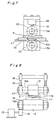
- the molding device comprises a generally rectangular container-like stationary die 1 having a longitudinal axis and a cylindrical counter roll 2 supported above the stationary die 1 for rotation about an axis of rotation lying perpendicular to the longitudinal axis of the stationary die 1 and also for movement in a direction parallel to the longitudinal axis of the stationary die 1.
- the illustrated molding device is used to mold a sheet molding compound (SMC) S to any desired shape, for example, a generally rectangular ribbed plate identified by 3 in Fig. 5 and is, as best shown in Fig. 6, operatively linked with a curing unit 4 which may comprise a heating device.
- SMC sheet molding compound
- the molding unit comprising the stationary die 1 and the counter roll 2 is so designed as to provide the rectangular ribbed plate 3 comprising a generally rectangular plate region 3c having one surface formed integrally with a longitudinal rib 3d that extends lengthwise of the plate region 3c and is positioned intermediate of the width thereof while representing a generally T-shaped sectional configuration.
- the stationary die 1 has a cavity 1a defined therein and opening upwardly through an top opening 1d and also has a bottom surface 1b formed with a rib-defining longitudinal recess 1c extending lengthwise of the stationary die 1 and positioned intermediate of the width thereof.
- the sheet molding compound S cut to have a shape substantially similar to the shape of the bottom surface 1c is placed inside the cavity 1a with a lower surface 3a thereof held in contact with the bottom surface 1b as shown in Figs. 1 to 3.
- the counter roll 2 is subsequently placed inside the cavity 1a of the stationary die 1 from above through the top opening 1d with its axis of rotation oriented perpendicular to the longitudinal axis of the stationary die 1.
- This counter roll 2 is operatively coupled not only with a pressing means (not shown) positioned above the counter roll 2 so that a pressing force can be transmitted to the sheet molding compound S within the stationary die 1 through the counter roll 2, but also with a drive means (not shown) so that the counter roll 2 while pressing the sheet molding compound S within the stationary die 1 can undergo a rotary motion about the axis of rotation thereof and, at the same time, a reciprocating motion in a direction parallel to the longitudinal axis of the stationary mold as indicated by the double arrow-headed line.
- the counter roll 2 is, while rotated about the axis of rotation thereof and moved in the direction lengthwise of the stationary die 1, lowered stepwise so that, after a desired or required number of passes of the counter roll 2 from one end of the stationary die 1 to the other, the sheet molding compound S within the stationary die 1 can be compacted to achieve a final degree of compression.
- the single pass of the counter roll 2 relative to the stationary die 1, during which the counter roll 2 is simultaneously rotated and moved relative to the stationary die 1, means a single movement of the counter roll 2 from one of the opposite ends of the stationary die 1 to the other and each double passes corresponds therefore to a single reciprocation of the shaping roll between the opposite ends of the stationary die 1.
- the thickness t of the sheet molding compound S after having been compacted corresponds to the thickness of the plate region 3c of the resultant ribbed plate 3.
- the pressure applied by the counter roll 2 to the sheet molding compound S within the stationary die 1 is lowered towards the stationary die 1 a predetermined small distance which may be of a value required for the sheet molding compound S to be compacted by a quantity corresponding to 1/5 to 1/100 of the final degree R of compression.
- the required number of passes of the counter roll 2 relative to the stationary die 1 can be determined once the final degree R of compression has been determined, that is, the extent to which the sheet molding compound S is desired to be compacted to provide an intended article of manufacture.
- the shaping of the sheet molding compound S performed by the counter roll 2 in cooperation with the stationary die 1 is carried out at room temperatures while the sheet molding compound S is in a semi-cured or substantially semi-cured state.
- the stationary die 1 accommodating therein the compacted sheet molding compound S is transported through any suitable transport means, for example, a conveyor 5, to the curing unit 4.
- the sheet molding compound S as molded within the stationary die 1 is heated to a temperature within the range of 80 to 150° for a predetermined time by a heating means 6, which may be a heater or a hot air blower, so that the sheet molding compound S containing a high temperature curing agent can be cured completely.
- a heating means 6 which may be a heater or a hot air blower, so that the sheet molding compound S containing a high temperature curing agent can be cured completely.
- the stationary die 1 having the cured sheet molding compound S is removed out of the curing unit, followed by a removal of the cured sheet molding compound S from the stationary die 1 thereby to complete the generally rectangular ribbed plate 3 shown in Fig. 5.
- the molding device shown in and described with reference to Figs. 1 to 6 are suited for a batch operation
- a molding device which is shown in and will now be described with reference to Figs. 7 and 8 is suited for a continuous molding of the sheet molding compound.
- the molding device shown therein is so designed as to receive a continuous web of sheet molding compound S from, for example, a roll of sheet molding compound and to mold it continuously to provide a ribbed strip which may, when cut, eventually provide a number of generally rectangular ribbed plates each similar to that shown in and described with reference to Fig. 5.
- the molding device shown in Figs. 7 and 8 comprises a mold support table 10 on which a movable die 11 having a cross-sectional representation identical or similar to that of the stationary die 1 employed in the foregoing embodiment of the present invention is placed for movement along the support table 10.
- the molding device shown therein also comprises upper or shaping and lower rolls 12 and 13 positioned one above the other on respective sides of the support table 10, said rolls 12 and 13 constituting a shaping unit by which the sheet molding compound S within the movable die 11 can be progressively pressed and be transported together with the movable die 11 in a direction downstream of the movable die 11.
- the lower roll 13 positioned generally beneath the support table 10 has a pair of stud shafts 13a coaxially protruding outwardly therefrom and rotatable together with the lower roll 13.
- One of the stud shafts 13a has a driven gear 14 which is meshed with a drive gear 16 rigidly mounted on a drive shaft of a drive unit, for example, an electric motor 15, so that the lower roll 13 can be driven by the motor 15 in a counterclockwise direction as viewed in Fig. 7 and as shown by the arrow.
- the support table 10 has a window 10a defined therein at a location immediately above the lower roll 13 to allow the lower roll 13 to partially protrude therethrough to contact an undersurface of the movable die 11. Therefore, during the rotation of the lower roll 13 in the counterclockwise direction, the movable die 11 can be moved in a direction conforming to the direction of rotation of the lower roll 13.
- the upper or shaping roll 12 rotatably supported immediately above the lower roll 13 is rotatably mounted on a drive shaft 12a so as to partially protrude into the cavity 11a of the movable die 11 to press the web of sheet molding compound within the movable die 11.
- the upper roll 12 is lowered towards the movable die 11 a predetermined small distance which may be of a value required for the sheet molding compound S to be compacted by a quantity corresponding to 1/5 to 1/100 of the final degree R of compression.
- the lowering of the upper roll 12 towards the movable die 11 can be accomplished by means of a feed screw mechanism 18 that includes at least one actuating rod 19 having a lower end operatively coupled with an associated bearing 17 rotatably supporting one end of the drive shaft 12a.
- a feed screw mechanism 18 that includes at least one actuating rod 19 having a lower end operatively coupled with an associated bearing 17 rotatably supporting one end of the drive shaft 12a.
- a curing unit (not shown) is arranged along the path of transport of the movable die 11 and at a location downstream of the support table 10 with respect to the direction of transport of the movable mold 11, which is effected after the required number of passes of the movable die 11 relative to the shaping unit has been accomplished, so that the web of sheet molding compound material S as molded within the movable die 11 can be heated to cure.
- an air cylinder may be employed for stepwise lowering the upper roll 12 towards the movable die 11.
- the web of sheet molding compound S placed inside the cavity 11a of the movable die 11 can be reciprocately moved beneath the upper roll 12 together with the movable die 11 during the rotation of the lower roll 13 and is, at the same time, compacted by the upper roll 12.
- the web of sheet molding compound S within the movable die 11 receives a relatively small pressing force for each pass of the movable die 11 relative to the upper roll 12 and is compacted stepwise as the movable die 11 undergoes the required number of passes relative to the upper roll 12.
- the web of sheet molding compound S having been compacted to achieve the final degree R of compression is transported through the curing means together with the movable die 11 for the heat treatment to cure it. Thereafter, the web of sheet molding compound is removed out of the movable die 11 and is then cut to provide a number of generally rectangular ribbed plates 3 shown in Fig. 5.
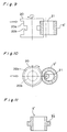
- Figs. 9, 10 and 11 illustrate a third preferred embodiment of the present invention wherein the molding device is so designed as to shape the sheet molding compound material S of a tubular shape to provide a generally radially ribbed tubular member 3' comprising, as best shown in Fig. 11, a tubular body having a radially outwardly protruding annular rib 3'a positioned intermediate of the length of the tubular body.
- the molding device comprises a generally cylindrical shaping roll 20 supported for rotation about an axis of rotation and having an outer peripheral surface formed with a radially inwardly depressed annular cavity 20a, the bottom of said annular cavity 20a being radially inwardly grooved to define a rib-defining annular recess 20b that is positioned intermediate the width of the annular cavity 20a.
- This shaping roll 20 is urged rightwards as viewed in Figs. 9 and 10 and as shown by the arrow by means of a pressing means (not shown) and is drivingly coupled with a drive means (not shown) so as to be driven about the axis of rotation thereof.
- a counter roll 21 Positioned on one side of and radially outwardly of the shaping roll 20 is a counter roll 21 supported for rotation about its own axis of rotation while being urged towards the shaping roll 20 by means of the pressing means referred to above.
- the tubular sheet molding compound S' is placed between the shaping roll 20 and the counter roll 21 with a wall portion thereof received within the cavity 20a as best shown in Fig. 10.
- the shaping roll 20 is driven in one direction about the axis of rotation thereof while being urged towards the counter roll 21 to successively compress that wall portion of the tubular sheet molding compound S'.
- the tubular sheet molding compound S' is rotated about the longitudinal axis thereof with its wall portion sandwiched between the shaping roll 20 and the counter roll 21 and, each time the tubular sheet molding compound S' completes a 360° rotation, the shaping roll 20 is moved towards the counter roll 21 a predetermined small distance which may be of a value required for the wall portion of the tubular sheet molding compound S' to be compacted radially inwardly by a quantity corresponding to 1/5 to 1/100 of the final degree R of compression, and at the same time, the direction of rotation of the shaping roll 20 and of the counter roll 21 is reversed.
- each complete rotation of the tubular sheet molding compound S' in one of the opposite directions effected in the manner hereinabove described corresponds to a single pass as used in connection with any one of the first and second embodiments of the present invention.
- the wall portion of the tubular sheet molding compound S' is radially inwardly compacted or compressed by the quantity corresponding to 1/5 to 1/100 of the final degree R of compression and that the required number of passes of the tubular sheet molding compound S' relative to the shaping roll 20 can be accomplished by repeatedly driving the shaping roll 20 clockwise and counterclockwise as viewed in Fig. 10.
- the wall portion of the tubular sheet molding compound S' can be compacted to achieve the final degree R of compression thereby to provide the radially ribbed tubular member 3' shown in Fig. 11.
- the shaping of the tubular sheet molding compound S' is carried out at normal temperatures while it is in a semi-cured or substantially semi-cured state and, after the shaping, the tubular sheet molding compound S' is heat-treated to cure.
- Figs. 12 to 14 illustrates the molding device according to a fourth preferred embodiment of the present invention.
- the molding device shown therein is so designed as to receive a continuous web of sheet molding compound material S'' of generally rectangular cross-sectional shape to shape it to provide, as best shown in Fig. 13 and 14, a curved ribbed member 3'' comprising a curved strip having outwardly and inwardly curved surfaces opposite to each other and also having the outwardly curved surface formed integrally with a correspondingly curved rib 3''a that protrudes outwardly therefrom and is positioned intermediate the width of the curved strip.
- the molding device has a curved transport path and comprises a plurality of shaping units disposed along the curved transport path and spaced a predetermined distance from each other in a direction generally parallel to the transport path.
- Each of the shaping units comprises a pair of shaping and counter rolls 30 and 31 positioned on respective sides of the transport path and adapted to be driven in respective directions counter to each other as shown by the associated arrows.
- Each of the shaping rolls 30 used in the practice of the fourth embodiment of the present invention is of a construction identical with or similar to the shaping roll 20 employed in the molding device according to the third embodiment of the present invention shown in Figs. 9 to 11 and is drivingly coupled with a common or separate drive means (not shown).
- the shaping rolls 30 are urged a different distance towards the associated counter rolls 31 by means of respective pressing means (not shown) so that, during the transport of the web of sheet molding compound S' along the curved transport path in a direction shown by the arrow, the web of sheet molding compound S' can be successively compacted or compressed inwardly.
- the shaping and counter rolls 30 and 31 of one of the shaping units which is positioned most upstream of the curved transport passage with respect to the direction of transport of the web of sheet molding compound S' are spaced from each other an initial distance which is greater than the final distance between the shaping and counter rolls 30 and 31 of one of the shaping units which is positioned most downstream of the curved transport passage while the distance between the shaping and counter rolls 30 and 31 of any one of the shaping units which is positioned intermediate between the upstream and downstream shaping means lies between the initial and final distances referred to above.
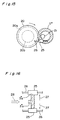
- the molding device shown therein is of a construction similar to that shown in and described with reference to Figs. 9 and 10 and is so designed as to provide the radially ribbed tubular member 3' shown in and described with reference to Fig. 11.
- the molding device shown in Figs. 15 and 16 differs from that shown in Figs. 9 and 10 in that a pair of constricting rolls 25 are employed on respective sides of the nipping region between the shaping roll 20 and the counter roll 21.
- the constricting rolls 25 are rotatably mounted on respective support shafts 26 extending generally perpendicular to the axis of rotation of any one of the shaping roll 20 and the counter roll 21 and are so positioned as to be held in contact with respective annular end faces 3''b of the tubular sheet molding compound material S' during the shaping operation to avoid any possible lateral deformation of the tubular sheet molding compound S' in a direction perpendicular to the direction in which the wall portion thereof is compacted inwardly.
- the opposite end portions of the tubular sheet molding compound S' tend to expand or flow laterally outwardly therefrom in a direction generally perpendicular to the direction of compression of the wall portion thereof.
- the constricting rolls 25 apply pressing forces to the respective opposite end faces 3''b of the tubular sheet molding compound S' in a direction perpendicular to the direction of compression thereby to suppress any possible lateral outward expansion of the end portions of the tubular sheet molding compound S' while permitting a portion of the tubular sheet molding compound S' intermediate between its opposite ends to fill up the rib-defining recess 20b substantially completely.
- pair of the constricting rolls 25 shown in and described with reference to Figs. 15 and 16 may be equally employed for each shaping unit the fourth embodiment shown in and described with reference to Figs. 12 to 14.
- the shaping roll 2, 12, 20 or 30 is drivingly coupled with the associated drive unit so that it can be driven at a constant speed while the sheet molding compound is transported also at a constant speed.
- the shaping roll is driven at the constant speed with the sheet molding compound transported at the constant speed.
- a generally rectangular testpiece 40 shown in Fig. 17 and made of sheet molding compound and being of a size having 300mm in length L, 50mm in width B and 10mm in thickness W1 was molded and shaped to provide such a rectangular ribbed plate 41 of generally T-shaped cross-section as shown in Fig. 18 which was subsequently tested as to the density and the bending stress.
- the resultant rectangular ribbed plate 41 comprises a rectangular plate region 41a, 3mm or 5mm in thickness W2, having one surface formed with a longitudinal rib 41b of 10mm in width Br and 8mm in height Hr.
- the testpiece 40 was of a composition containing 14.3 wt% of unsaturated polyester resin, 51.4 wt% of calcium carbonate, 20 wt% of glass fibers and 14.4 wt% of various additives including a solution of thermoplastic resin, a curing agent (tertiary butyl peroxy benzoate), a thickener and an inner mold releasing agent.
- various additives including a solution of thermoplastic resin, a curing agent (tertiary butyl peroxy benzoate), a thickener and an inner mold releasing agent.
- Each of the glass fibers used had a fiber length of 1 inch.
- the final degree R of compression which is 0.50 and 0.70 was employed.
- the strength test conducted was a three-point bending test performed on the plate region of the resultant ribbed plate in the lengthwise direction thereof according to the method stipulated in JIS (Japanese Industrial Standards) K705S.
- the graph of Fig. 19 suggests that, even when the distance E of stepwise movement of the shaping roll is changed to 0.50mm and 0.25mm, the density of the resultant shaped article may be little affected. However, the choice of the relatively large distance E of 0.50mm can result in a considerable increase in the maximum bending stress exhibited by the plate region of the shaped article.
- the density and the maximum bending stress were tested of the shaped article molded and shaped with the use of the shaping roll of 60mm and 120mm in outer diameter D, results of which are shown in the graph of Fig. 20.
- the greater the outer diameter of the shaping roll the greater the density in the plate region than that in the rib region.
- the smaller the outer diameter of the shaping roll the lower the density in the plate region than that in the rib region.
- a difference in processing speed allows the material to fluidize in a direction, conforming to the direction in which the rib region protrudes from the plate region, if the shaping roll has a relatively small outer diameter.
- the maximum bending stress exhibited by the plate region gives a higher value when the shaping roll has a relatively small outer diameter than when it has a relatively great outer diameter.
- the material tends to flow considerably in the direction conforming to the direction in which the rib region protrudes from the plate region, and therefore, the glass fibers will not be oriented two-dimensionally to such an extent as to result in a reduction in bending strength.
- a molding device according to a sixth preferred embodiment of the present invention.
- the shaping roll or rolls are driven at the constant speed to transport or rotate the sheet molding compound at the constant speed while the compressing pressure is applied thereto in stepwise fashion.
- the outer diameter of the shaping roll is fixed, it is possible to manufacture the shaped article having an isotropic strength without allowing the internal reinforcement fibers to be oriented in particular direction, but oriented uniformly in all directions.
- the use of the shaping roll of a different outer peripheral surface is effective to bias the reinforcement fibers so as to be oriented in one particular direction so that the resultant shaped article can have an anisotropic strength.
- the illustrated molding device comprises a plurality of, for example, first to fourth, compressing stages defined one after another along the transport path through which a web of sheet molding compound S' is transported, each of said compressing stages including a pair of counter and shaping rolls 50A and 51A, 50B and 51B, 50C and 51C, 50D and 51D, positioned one after on respective sides of the transport path.
- the counter rolls 50A to 50D of the respective compressing stages are supported stationary and are drivingly coupled with respective drive units (not shown) used to drive the counter rolls 50A to 50D at first to fourth different speeds, respectively, in a direction shown by the arrow so that the web of sheet molding compound S' can be transported at a varying speed from an upstream side adjacent the first compressing stage towards a downstream side adjacent the fourth compressing stage.
- the first speed at which the counter roll 50A of the first compressing stage is driven is chosen to be the lowest of all whereas the fourth speed at which the counter roll 50D of the fourth compressing stage is driven is chosen to be the highest of all, with the speed stepwisely increasing from the first compressing stage to the fourth compressing stage.
- the respective speeds of rotation of the counter rolls 50A to 50D driven by the associated drive units are so selected that the web of sheet molding compound material S' can be transported from the upstream side towards the downstream side along the transport path at an average transport speed within the range of 0.5 to 2 meters per minute (5 meters per minute at a maximum average transport speed).
- a single drive unit may be employed in combination with a train of reduction gears designed to drive the counter rolls 50A to 50D at the respective first to fourth speeds.
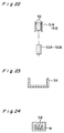
- Each of the shaping rolls 51A to 51D of the respective first to fourth compressing stages is of a construction comprising, as best shown in Fig. 22, a cylindrical body having an outer peripheral surface formed with a pair of annular grooves 52 defined adjacent the opposite ends thereof and is rotatably supported above the associated counter roll 50A to 50D.
- Each of the shaping rolls 51A to 51D is operatively coupled with a respective screw feed mechanism 18 shown in and described with reference to Figs. 7 and 8 so that the minimum distance S between the shaping roll 50A to 50D and the associated counter roll 51A to 51D, or the size of a respective nipping region defined therebetween, can be adjusted.
- the distance S is chosen to be stepwisely decreased in the order from that in the first compressing stage towards the fourth compressing stage while the difference in distance S between each neighboring pairs of the shaping and counter rolls 50A and 51A, 50B and 51B, 50C and 51C, 50D and 51D is chosen to be within the range of 2 to 25mm.
- the difference in distance S between each neighboring pairs of the rolls is chosen to be rather small and, where the difference in thickness between the sheet molding compound material and the resultant shaped article made of such sheet molding compound is large, the number of the compressing stages, that is, the number of the pairs of the shaping and counter rolls, may be increased.
- each of all of the shaping and counter rolls 51A to 51D and 50A to 50D has a uniform outer diameter of 200mm, and the use is made of a guide roll 55 of smaller outer diameter disposed and rotatably supported in position between each neighboring counter rolls 50A to 50D for supporting from below the web of sheet molding compound material S' being transported along the transport path.
- the molding device of the above described construction according to the sixth embodiment of the present invention includes the curing unit 4, a cutting unit 56 and a delivery table 57 which are sequentially disposed downstream of the fourth compressing stage as shown in Fig. 21. Therefore, the web of sheet molding compound having successively been processed through the first to fourth compressing stages is transported into the curing unit 4, in which the compacted sheet molding compound is cured, and is, as it emerges outwardly from the curing unit 4, cut by the cutting unit 56 into shaped articles which are subsequently received onto the delivery table 57.
- each of the shaped articles referred to above is generally identified by 3x in Fig. 23 having a generally U-shaped cross-section.
- the curing unit 4 used in the practice of the sixth embodiment of the present invention has a guide passage 58 defined therein so as to extend completely across the curing unit 4 and having a generally U-shaped configuration complemental to the cross-sectional shape of the resultant shaped article 3x.
- This curing unit 4 includes, as best shown in Fig. 21, a guide region 4A, a primary curing region 4B, a secondary curing region 4C and a final curing region 4D defined therein from an upstream end thereof towards a downstream end thereof.
- each respective portions of the guide passage 58 in the curing unit 4 encompassed by the guide region 4A and the primary curing region 4B is somewhat oversized to provide a clearance between an outer perimeter of the compacted sheet molding compound being passed therethrough and a wall surface defining such portions of the guide passage 58
- a portion of the guide passage 58 encompassed by the secondary curing region 4C is somewhat either oversized or undersized relative to the cross-sectional shape of the compacted sheet molding compound depending on thermal characteristics of the sheet molding compound.
- the curing unit 4 has its interior heated to 150°C.
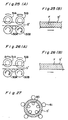
- the speed of rotation of one of the counter rolls 51A to 51D is chosen to be higher than the speed of rotation of any one of the counter rolls 51A to 51D which is positioned upstream of said one of the counter rolls with respect to the direction of transport of the web of sheet molding compound S', a tensile force acts on the sheet molding compound S' in a downstream direction thereby allowing the internal reinforcement fibers F to be oriented in a direction conforming to the direction in which the tensile force acts, that is, in a horizontal direction, as shown in Fig. 25(B).
- the reinforcement fibers F contained in the web of sheet molding compound S' can be substantially uniformly oriented horizontally.
- the web of sheet molding compound S' After the web of sheet molding compound S' has successively passed through the first to fourth compressing stages in the manner described above, the web of sheet molding compound S' is transported through the curing unit 4 and is then cut by the cutting unit 56 into the resultant shaped articles each having a predetermined length. During the passage of the web of sheet molding compound S' through the second curing region 4C of the curing unit 4, a surface smoothness is imparted to an entire surface of the compacted web of sheet molding compound S'.
- Each of the resultant shaped articles so manufactured in the manner described above has an anisotropy in which it has a higher strength in a direction conforming to the direction of orientation of the reinforcement fibers than in any other directions.
- Figs. 26(A) and 26(B) illustrate a modification of the sixth embodiment of the present invention.
- the speed of rotation of one of the counter rolls 51A to 51D is chosen to be lower than the speed of rotation of any one of the counter rolls 51A to 51D which is positioned upstream of said one of the counter rolls with respect to the direction of transport of the web of sheet molding compound S'.
- the first speed at which the counter roll 50A of the first compressing stage is driven is chosen to be the highest of all whereas the fourth speed at which the counter roll 50D of the fourth compressing stage is driven is chosen to be the lowest of all, with the speed stepwisely decreasing from the first compressing stage to the fourth compressing stage.
- each resultant shaped article can have an anisotropy in which it has a relatively high strength in a direction generally perpendicular to the direction in which it has been transported.
- the orientation of the reinforcement fibers contained in the web of sheet molding compound takes place progressively, not at one time, and, therefore, by suitably selecting the number of the compressing stages and/or the first to fourth speed of rotation of the counter rolls 50A to 50D, the reinforcement fibers contained in the web of sheet molding compound can be oriented in both of the horizontal direction as shown in Fig. 25(B) and the direction generally perpendicular to the direction of transport as shown in Fig. 26(B), that is, oriented in part in the horizontal direction and in part in the direction perpendicular to the direction of transport of the web S'.
- the reinforcement fibers can be oriented in any particular direction or directions as desired, and the present invention is effective to provide the shaped articles having a relatively high strength in such particular direction or directions depending on the application of such shaped articles.
- the shaping unit may have any suitable construction and, at the same time, the curing unit may also have any suitable construction.
- the curing unit may be of a construction which comprises, as shown in Fig. 27, an inner circular row of generally elongated rolls 60 and an outer circular row of generally elongated rolls 61 positioned radially outwardly of the inner circular row of the rolls 61 in face-to-face relationship with the associated rolls 60.
- the annular wall portion of the web is supported between the inner rolls 60 and the mating outer rolls 61 while heated by those rolls 60 and 61 which are heated to the predetermined temperature.
- the molding method and the molding device according to the present invention are effective to provide the shaped article of manufacture made of sheet molding compound (which may be a prepreg sheet) or thick molding compound (TMC) material, in which the orientation of the reinforcement fibers have been controlled with no possibility that they are oriented in any unexpected direction. Therefore, it is possible, for example, to provide the shaped article having an isotropy in which the reinforcement fibers are uniformly oriented in all directions and also to provide the shaped article having an anisotropy in which the reinforcement fibers are oriented in the required particular direction.
- sheet molding compound which may be a prepreg sheet
- TMC thick molding compound
- the orientation of the reinforcement fibers can be controlled so that the resultant shaped article can have a required strength, the shaped article can have favorable physical characteristics. Also, with a progressive increase of the extent to which the sheet molding compound is compressed inwardly, both of the density and the maximum bending stress of the resultant shaped article can be increased.
- the fiber reinforced resinous material can be automatically delivered by the shaping unit, the power required to transport the fiber reinforced resinous material can be reduced considerably.
- the shape of the articles formed by the continuous molding and shaping operation may not be always limited to those discussed hereinbefore.
- the molding method and the molding device according to the present invention are intended for use with the fiber reinforced resinous material which is made of dry material, as compared with the molding and shaping of wet material, they would substantially bring about no environmental problem and are effective to precisely manufacture the shaped articles.
Landscapes
- Engineering & Computer Science (AREA)
- Chemical & Material Sciences (AREA)
- Textile Engineering (AREA)
- Mechanical Engineering (AREA)
- Inorganic Chemistry (AREA)
- Composite Materials (AREA)
- Manufacturing & Machinery (AREA)
- Casting Or Compression Moulding Of Plastics Or The Like (AREA)
Description
Claims (18)
- A method for molding a fiber reinforced resinous material (S; S'; S'') comprising preparing a semi-cured fiber reinforced resinous material (S; S'; S'') by impregnating reinforcement fibers with resin and shaping said resinous material (S; S'; S'') in a die by means of rolls,
characterized by(a) positioning said resinous material (S; S'; S'') between a die (1; 11; 20; 30; 51A-51D) and a counter roll (2; 12; 21; 31; 50A-50D) spaced from the die (1; 11; 20; 30; 51A-51D) at an initial distance, the die (1; 11; 20; 30; 51A-51D) and the counter roll (2; 12; 21; 31; 50A-50D) forming a shaping unit;(b) rotating the counter roll (2; 12; 21; 31; 50A-50D) about an axis perpendicular to the extension of the die (1; 11; 20; 30; 51A-51D), and providing a movement of said resinous material (S; S'; S'') relative to the counter roll (2; 12; 21; 31; 50A-50D) and the die (1; 11; 20; 30; 51A-51D);(c) shaping said resinous material (S; S'; S'') in a stepwise manner by repeating step (b) whith stepwise reduction of the initial distance between the die (1; 11; 20; 30; 51A-51D) and the counter roll (2; 12; 21; 31; 50A-50D) to compress said resinous material (S; S'; S'') with stepwise increase in pressure, whereby the reinforcement fibers contained in said resinous material are orientated in a predetermined direction. - The method of claim 1, characterized in that the increase in pressure per step is within the range of 1/5 to 1/100 of the pressure corresponding to the final degree of compression.
- The method of claim 1 or 2, utilized for molding said resinous material (S) in a batch mode process to have an elongate shape, characterized in that the die is a flat stationary die (1), the counter roll (2) being positioned above the stationary die (1) and subjected to both a rotary motion about its axis of rotation and a reciprocating motion in a direction parallel to the longitudinal axis of the stationary die (1).
- The method of claim 1 or 2, utilized for molding said resinous material (S') in a batch mode process to have a tubular shape, characterized in that the die is a cylindrical shaping roll (20), the counter roll (21) being positioned at one side of and radially outward of the shaping roll (20), wherein said shaping roll (20) is subjected to a rotation about its axis of rotation with the direction of rotation reversed after completion of 360 °.
- The method of claim 4, characterized by applying a pressing force to the opposite end faces (3''b) of said resinous material (S'') molded into a tubular shape, said pressing force being achieved by a pair of rotatable constricting rolls (25) employed on the sides of the nipping region between the shaping roll (20) and the counter roll (21) and positioned to be in contact with said end faces (3''b) to avoid lateral deformation of the tubular shape.
- The method of claim 1 or 2, utilized for molding said resinous material (S'; S'') in a continuous mode process to have an elongate and/or curved shape, characterized in that the stepwise reduction of the initial distance is provided by utilizing multiple shaping units having decreasing distances between cylindrical shaping rolls (30; 51A-51D) and counter rolls (31; 50A-50D).
- The method of anyone of the preceeding claims, characterized in that a uniform transport speed is applied to said resinous material in order to obtain reinforcement fibers having an isotropic orientation.
- The method of claim 6, characterized in that a non-uniform transport speed is applied to said resinous material in order to obtain reinforcement fibers having an anisotropic orientation.
- The method of claim 8, characterized in that the transport speed is made non-uniform by applying a lower upstream transport speed to said resinous material in order to achieve anisotropic orientation of the reinforcement fibers parallel to the transport direction.
- The method of claim 8, characterized in that the transport speed is made non-uniform by applying a higher upstream transport speed to said resinous material in order to achieve anisotropic orientation of the reinforcement fibers perpendicular to the transport direction.
- The method of anyone of the preceeding claims, characterized by further comprising a step of curing said resinous material after the shaping step.
- An apparatus for conducting the method of anyone of the preceeding claims, comprisinga shaping unit comprising a movable die (11) and a counter roll (12) spaced from said die (12) at an initial distance;means (18, 19) for lowering the counter roll (12) against said die (11); and driving means (12a, 17, 13, 13a, 14, 15, 16);
characterized in thatsaid die (11) has a flat shape;said driving means (12a, 17, 13, 13a, 14, 15, 16) are adapted to rotate the counter roll (12) at a variable speed and to provide a reciprocating movement of said die (11) relative to the counter roll (12); andsaid lowering means (18, 19) are adapted to apply a stepwise increase in pressure to said resinous material (S) contained in said die (11) each time said material (S) is passed beneath the counter roll (12) by said reciprocating movement, said increase being effected by a stepwise decrease of the initial distance between the die (11) and the counter roll (12) until a desired thickness of said material (S) is achieved. - The apparatus of claim 12, characterized by further comprising a curing unit (4) for curing said resinous material (S) after shaping.
- The apparatus of claim 12, further characterized by a constricting means (25, 26) for avoiding any deformation of said resinous material (S) in a direction other than that in which pressure is applied.
- An apparatus for conducting the method of anyone of claims 1 to 11 in a continuous mode,
characterized bymultiple shaping units arranged at a plurality of stages spaced along a transport path of said resinous material (S) to be molded,the shaping units comprising rotatable cylindrical shaping rolls (30; 51A-51D) and rotatable counter rolls (31; 50A-50D) spaced from said die (30; 51A-51D) at a distance,
wherein the shaping units are adapted to apply a stepwise increase in pressure to said resinous material (S) along the transport path by a stepwise decrease of the distance between the die (30; 51A-51D) and the counter roll (31; 50A-50D). - The apparatus of claim 15, characterized in that the speed of the transport movement varies along the transportation path from stage to stage in a stepwise manner.
- The apparatus of claim 16, characterized in that said variation is provided by varying the rotation speed of the rolls (30; 51A-51D; 31; 50A-50D).
- The apparatus of claim 16 or 17, characterized in that the transport decreases or increases from upstream stages to downstream stages.
Applications Claiming Priority (2)
| Application Number | Priority Date | Filing Date | Title |
|---|---|---|---|
| JP4702091 | 1991-03-12 | ||
| JP47020/91 | 1991-03-12 |
Publications (2)
| Publication Number | Publication Date |
|---|---|
| EP0503554A1 EP0503554A1 (en) | 1992-09-16 |
| EP0503554B1 true EP0503554B1 (en) | 1998-06-03 |
Family
ID=12763502
Family Applications (1)
| Application Number | Title | Priority Date | Filing Date |
|---|---|---|---|
| EP92104058A Expired - Lifetime EP0503554B1 (en) | 1991-03-12 | 1992-03-10 | Molding method and apparatus |
Country Status (3)
| Country | Link |
|---|---|
| US (2) | US5352110A (en) |
| EP (1) | EP0503554B1 (en) |
| DE (1) | DE69225733T2 (en) |
Families Citing this family (20)
| Publication number | Priority date | Publication date | Assignee | Title |
|---|---|---|---|---|
| US5484276A (en) * | 1992-11-20 | 1996-01-16 | Takeda Chemical Industries, Ltd. | Curing apparatus for molding compound |
| FI930826A0 (en) * | 1993-02-24 | 1993-02-24 | Uponor Nv | OIL ANCHORING FOER ATT FRAMSTAELLA KAMFLAENSAR MED SIDOUTBUKTNINGAR I PLASTROER OCH ETT PLASTROER |
| US5891379A (en) * | 1995-02-08 | 1999-04-06 | Auckland Uniservices Limited | Roll forming of thermoplastics |
| JP3447518B2 (en) * | 1996-08-09 | 2003-09-16 | リンテック株式会社 | Adhesive sheet sticking apparatus and method |
| US5980802A (en) | 1997-04-11 | 1999-11-09 | Wagner Spray Tech Corporation | Method for treating paint roller covers |
| US6203309B1 (en) * | 1998-08-10 | 2001-03-20 | Wagner Spray Tech Corporation | Apparatus for embossing paint rollers |
| US6408595B1 (en) | 1999-11-02 | 2002-06-25 | Union Scientific Corporation | Microplate cover seal applicator |
| WO2002026455A2 (en) * | 2000-09-29 | 2002-04-04 | Steinhoff Manufacturing (Pty) Ltd. | Method and apparatus for moulding synthetic wood and product used therein |
| WO2002083397A1 (en) * | 2001-04-17 | 2002-10-24 | Allegheny Solid Surface Technologies | Methods and arrangements for texturing, patterning and bending polymer sheet materials |
| US20040021250A1 (en) * | 2002-07-31 | 2004-02-05 | Obeshaw Dale F. | Method of manufacturing a sheet-molded compound article having localized reinforcement |
| CN101372140B (en) * | 2007-08-21 | 2011-07-27 | 鸿富锦精密工业(深圳)有限公司 | Roll forming device |
| DE102011015607A1 (en) * | 2011-03-30 | 2012-10-04 | Thomas Gmbh + Co. Technik + Innovation Kg | Method and device for producing a reinforcing plastic profile |
| WO2014021831A1 (en) * | 2012-07-31 | 2014-02-06 | Compagnie Generale Des Etablissements Michelin | Management of throughput of elastomeric mixes through calendering drives |
| FR3000971B1 (en) * | 2013-01-11 | 2016-05-27 | Saint Gobain Isover | THERMAL INSULATION PRODUCT BASED ON MINERAL WOOL AND PROCESS FOR PRODUCING THE PRODUCT |
| DE102013226739A1 (en) * | 2013-12-19 | 2015-06-25 | Airbus Operations Gmbh | Forming tool, shaping device and method for deforming a semifinished fiber containing reinforcing fibers |
| US10232572B2 (en) * | 2014-08-27 | 2019-03-19 | The Boeing Company | Composite filler forming apparatus |
| EP3408434B1 (en) | 2016-01-26 | 2025-06-25 | Continental Structural Plastics, Inc. | Process and system of debundling fiber tow for use in preform mats and molding compositions containing such fibers |
| EP3354433A1 (en) * | 2017-01-31 | 2018-08-01 | Covestro Deutschland AG | Device with free-running cooling rollers for producing a fibre composite in the form of a fibre strip impregnated with polymer, method for producing said fibre strip, an impregnated fibre strip and multilayer structure made from the impregnated composite |
| EP3466659A1 (en) * | 2017-10-06 | 2019-04-10 | Covestro Deutschland AG | Pultrusion method for producing fibre-reinforced plastic profiles and pultrusion device |
| CN110919951B (en) * | 2019-11-18 | 2020-08-21 | 江苏鸿凌达科技有限公司 | Method and die for preparing graphene fiber oriented heat conducting sheet by adopting die pressing |
Family Cites Families (32)
| Publication number | Priority date | Publication date | Assignee | Title |
|---|---|---|---|---|
| US736217A (en) * | 1901-12-28 | 1903-08-11 | Electric Vehicle Equipment Company | Secondary-battery plate and method of making same. |
| US2620513A (en) * | 1950-03-08 | 1952-12-09 | Union Asbestos & Rubber Co | Method of and apparatus for forming pipe insulation |
| US2674764A (en) * | 1950-10-31 | 1954-04-13 | Armstrong Cork Co | Method of forming flanged articles |
| GB759092A (en) * | 1953-06-11 | 1956-10-10 | Eugen Bentz | A process for the manufacture of moulded articles of reinforced plastic material |
| US2852806A (en) * | 1953-09-25 | 1958-09-23 | Erdelyi Ferenc | Means for manufacturing substantially sleeve-shaped articles closed at one end and provided with an internal thread |
| US2779388A (en) * | 1954-08-02 | 1957-01-29 | Henry N Quoss | Apparatus and method of forming elongate articles from fiberglas |
| NL260079A (en) * | 1960-01-15 | |||
| US3299837A (en) * | 1963-11-27 | 1967-01-24 | Joseph M Lind | Dough sheeter |
| US3274322A (en) * | 1964-03-09 | 1966-09-20 | Chemechanical Inc | Method of flow forming polyurethane and like material |
| DE1504491A1 (en) * | 1964-10-05 | 1970-04-30 | Koppers Co Inc | Method and device for the production of molded parts from bonded fibrous materials |
| US3469960A (en) * | 1966-10-14 | 1969-09-30 | Max Putzig | Apparatus for producing mineral wool |
| SE333238B (en) * | 1966-12-12 | 1971-03-08 | Defibrator Ab | KIT AND DEVICE FOR TREATING VEGETABLE MATERIAL PLATES |
| US3583030A (en) * | 1967-05-26 | 1971-06-08 | Johns Manville | Apparatus for the continuous forming of fibrous products by continuously compressing and curing binder containing fibrous material |
| US3469609A (en) * | 1967-07-11 | 1969-09-30 | Smith Co Howard | Apparatus for making well screen |
| US3571849A (en) * | 1969-05-21 | 1971-03-23 | Gen Electric | Rolling mill apparatus for high pressure generation |
| BE795465A (en) * | 1972-02-15 | 1973-08-16 | Borden Chem France | INSTALLATION FOR THE MANUFACTURE OF RESIN BONDED CONCRETE PANELS |
| US3901634A (en) * | 1972-11-09 | 1975-08-26 | John B Webb | Compactor for producing cement wall panels |
| FR2276914A1 (en) * | 1974-07-04 | 1976-01-30 | Kroyer St Annes Ltd Karl | MOLDING APPARATUS |
| ZA786821B (en) * | 1977-12-19 | 1979-11-28 | Courtaulds Ltd | Forming a sheet of fibrous material |
| US4238178A (en) * | 1979-05-18 | 1980-12-09 | Bailey James G | Slab roller machine |
| JPS56161126A (en) * | 1980-05-16 | 1981-12-11 | Mitsubishi Petrochem Co Ltd | Preparation of synthetic resin foamed body with excellent bending strength |
| NL8100256A (en) * | 1981-01-20 | 1982-08-16 | Brinkers Margarinefab | Apparatus for rolling out a dough mass to be supplied in the form of a thick layer to a continuous sheet. |
| US4474845A (en) * | 1982-08-26 | 1984-10-02 | General Motors Corporation | Compacted sheet molding compound |
| JPS6119444A (en) * | 1984-07-07 | 1986-01-28 | レオン自動機株式会社 | Apparatus for exending plastic material |
| US4789514A (en) * | 1985-12-09 | 1988-12-06 | Aluminum Company Of America | Methods of producing biaxially oriented polymer sheet |
| US5102609A (en) * | 1986-02-03 | 1992-04-07 | The Board Of Trustees Of The Leland Stanford Junior University | Process for forming fiber composite materials |
| US4777005A (en) * | 1986-02-03 | 1988-10-11 | The Board Of Trustees Of The Leland Stanford Junior University | Process for shaping fiber composite materials |
| US4818460A (en) * | 1986-03-24 | 1989-04-04 | General Electric Company | Roller forming of thermoplastic sheet material |
| JPH01184241A (en) * | 1988-01-18 | 1989-07-21 | Honda Motor Co Ltd | Premolded body for short fiber composites, material for the same and controlling fiber orientation of the same |
| US5041178A (en) * | 1988-06-27 | 1991-08-20 | Manville Corporation | Method of manufacturing a fibrous board |
| US4927581A (en) * | 1988-10-19 | 1990-05-22 | E. I. Du Pont De Nemours And Company | Method for shaping fiber reinforced resin matrix materials |
| JPH0795910B2 (en) * | 1989-07-28 | 1995-10-18 | レオン自動機株式会社 | Fabric spreading method and device |
-
1992
- 1992-03-10 US US07/849,662 patent/US5352110A/en not_active Expired - Fee Related
- 1992-03-10 EP EP92104058A patent/EP0503554B1/en not_active Expired - Lifetime
- 1992-03-10 DE DE69225733T patent/DE69225733T2/en not_active Expired - Fee Related
-
1994
- 1994-07-08 US US08/271,053 patent/US5533880A/en not_active Expired - Fee Related
Also Published As
| Publication number | Publication date |
|---|---|
| EP0503554A1 (en) | 1992-09-16 |
| DE69225733D1 (en) | 1998-07-09 |
| US5533880A (en) | 1996-07-09 |
| DE69225733T2 (en) | 1998-10-01 |
| US5352110A (en) | 1994-10-04 |
Similar Documents
| Publication | Publication Date | Title |
|---|---|---|
| US5352110A (en) | Molding apparatus for molding fiber reinforced resin with plurality of roll pairs | |
| JP2634184B2 (en) | Method for producing thermoplastic polymer profiled section by pultrusion molding, apparatus for carrying out this method and product obtained thereby | |
| US4726924A (en) | Method of planar forming of zero degree composite tape | |
| EP0531473B1 (en) | Polymeric materials | |
| US4720255A (en) | Apparatus for planar forming of zero degree composite tape | |
| EP2914415B1 (en) | Method and apparatus for forming thermoplastic composite structures | |
| US5026514A (en) | Incremental forming of thermoplastic composites | |
| US20110206906A1 (en) | Continuous Molding of Thermoplastic Laminates | |
| US3915783A (en) | Making a thermosetting resin impregnating laminate | |
| US20060071369A1 (en) | Apparatus for the continuous production of plastic composites | |
| US5202071A (en) | Method of producing fiber reinforced plastic moldings | |
| US3226458A (en) | Method and apparatus for continuously producing molded articles and sectional sheets of plastics | |
| DE1901828A1 (en) | Producing foamed composite bodies | |
| EP2186627B1 (en) | Method for continuously forming composite material shape member having varied cross-sectional shape | |
| US3477894A (en) | Apparatus for producing molded plastic goods | |
| US4229398A (en) | Method and apparatus for the continuous production of a block of reconstituted foam material | |
| US4913764A (en) | Device for manufacturing shells of mineral fibers | |
| US5043034A (en) | Post forming semi-finished product for the manufacture of moulded parts resistant to bending | |
| CN113021936A (en) | Continuous molding device and molding method for thermoplastic composite material sandwich structure | |
| JPH0569450A (en) | Method and apparatus for molding fiber reinforced resin material | |
| US3053717A (en) | Reinforced continuous sheeting and the method and apparatus for making same | |
| JPH0698614B2 (en) | Method for continuously producing shaped body of fiber-reinforced hydraulic mass | |
| CN111746005A (en) | Variable-curvature continuous reinforced plastic fiber pultrusion equipment and processing method thereof | |
| CN111136936B (en) | Multi-angle layering design cap-shaped stringer prepreg pultrusion device | |
| USRE25200E (en) | Method of making a composite sheet |
Legal Events
| Date | Code | Title | Description |
|---|---|---|---|
| PUAI | Public reference made under article 153(3) epc to a published international application that has entered the european phase |
Free format text: ORIGINAL CODE: 0009012 |
|
| AK | Designated contracting states |
Kind code of ref document: A1 Designated state(s): DE FR GB IT |
|
| 17P | Request for examination filed |
Effective date: 19930219 |
|
| 17Q | First examination report despatched |
Effective date: 19940819 |
|
| GRAG | Despatch of communication of intention to grant |
Free format text: ORIGINAL CODE: EPIDOS AGRA |
|
| GRAG | Despatch of communication of intention to grant |
Free format text: ORIGINAL CODE: EPIDOS AGRA |
|
| GRAG | Despatch of communication of intention to grant |
Free format text: ORIGINAL CODE: EPIDOS AGRA |
|
| GRAH | Despatch of communication of intention to grant a patent |
Free format text: ORIGINAL CODE: EPIDOS IGRA |
|
| RHK1 | Main classification (correction) |
Ipc: B29C 70/08 |
|
| GRAH | Despatch of communication of intention to grant a patent |
Free format text: ORIGINAL CODE: EPIDOS IGRA |
|
| GRAA | (expected) grant |
Free format text: ORIGINAL CODE: 0009210 |
|
| AK | Designated contracting states |
Kind code of ref document: B1 Designated state(s): DE FR GB IT |
|
| ITF | It: translation for a ep patent filed | ||
| REF | Corresponds to: |
Ref document number: 69225733 Country of ref document: DE Date of ref document: 19980709 |
|
| ET | Fr: translation filed | ||
| PGFP | Annual fee paid to national office [announced via postgrant information from national office to epo] |
Ref country code: GB Payment date: 19990311 Year of fee payment: 8 |
|
| PGFP | Annual fee paid to national office [announced via postgrant information from national office to epo] |
Ref country code: DE Payment date: 19990329 Year of fee payment: 8 |
|
| PGFP | Annual fee paid to national office [announced via postgrant information from national office to epo] |
Ref country code: FR Payment date: 19990331 Year of fee payment: 8 |
|
| PLBE | No opposition filed within time limit |
Free format text: ORIGINAL CODE: 0009261 |
|
| STAA | Information on the status of an ep patent application or granted ep patent |
Free format text: STATUS: NO OPPOSITION FILED WITHIN TIME LIMIT |
|
| 26N | No opposition filed | ||
| PG25 | Lapsed in a contracting state [announced via postgrant information from national office to epo] |
Ref country code: GB Free format text: LAPSE BECAUSE OF NON-PAYMENT OF DUE FEES Effective date: 20000310 |
|
| GBPC | Gb: european patent ceased through non-payment of renewal fee |
Effective date: 20000310 |
|
| PG25 | Lapsed in a contracting state [announced via postgrant information from national office to epo] |
Ref country code: FR Free format text: LAPSE BECAUSE OF NON-PAYMENT OF DUE FEES Effective date: 20001130 |
|
| REG | Reference to a national code |
Ref country code: FR Ref legal event code: ST |
|
| PG25 | Lapsed in a contracting state [announced via postgrant information from national office to epo] |
Ref country code: DE Free format text: LAPSE BECAUSE OF NON-PAYMENT OF DUE FEES Effective date: 20010103 |
|
| PG25 | Lapsed in a contracting state [announced via postgrant information from national office to epo] |
Ref country code: IT Free format text: LAPSE BECAUSE OF NON-PAYMENT OF DUE FEES Effective date: 20050310 |