EP0503185B1 - Multimeter having min/max time stamp - Google Patents
Multimeter having min/max time stamp Download PDFInfo
- Publication number
- EP0503185B1 EP0503185B1 EP91305480A EP91305480A EP0503185B1 EP 0503185 B1 EP0503185 B1 EP 0503185B1 EP 91305480 A EP91305480 A EP 91305480A EP 91305480 A EP91305480 A EP 91305480A EP 0503185 B1 EP0503185 B1 EP 0503185B1
- Authority
- EP
- European Patent Office
- Prior art keywords
- value
- time
- minimum
- maximum
- stored
- Prior art date
- Legal status (The legal status is an assumption and is not a legal conclusion. Google has not performed a legal analysis and makes no representation as to the accuracy of the status listed.)
- Expired - Lifetime
Links
- 238000000034 method Methods 0.000 claims description 48
- 238000005259 measurement Methods 0.000 claims description 46
- 230000004044 response Effects 0.000 claims description 2
- 230000008569 process Effects 0.000 description 32
- 230000006870 function Effects 0.000 description 10
- 238000010586 diagram Methods 0.000 description 8
- 238000012360 testing method Methods 0.000 description 4
- 102000020897 Formins Human genes 0.000 description 3
- 108091022623 Formins Proteins 0.000 description 3
- 230000000881 depressing effect Effects 0.000 description 3
- 238000012544 monitoring process Methods 0.000 description 3
- 230000000994 depressogenic effect Effects 0.000 description 2
- 238000012986 modification Methods 0.000 description 2
- 230000004048 modification Effects 0.000 description 2
- 238000012545 processing Methods 0.000 description 2
- 241000272173 Calidris Species 0.000 description 1
- 210000001072 colon Anatomy 0.000 description 1
- 230000008878 coupling Effects 0.000 description 1
- 238000010168 coupling process Methods 0.000 description 1
- 238000005859 coupling reaction Methods 0.000 description 1
- 230000001788 irregular Effects 0.000 description 1
- 239000004973 liquid crystal related substance Substances 0.000 description 1
- 230000000737 periodic effect Effects 0.000 description 1
- 238000005070 sampling Methods 0.000 description 1
- 230000001629 suppression Effects 0.000 description 1
- 238000013024 troubleshooting Methods 0.000 description 1
- 230000000007 visual effect Effects 0.000 description 1
Images




Classifications
-
- G—PHYSICS
- G01—MEASURING; TESTING
- G01D—MEASURING NOT SPECIALLY ADAPTED FOR A SPECIFIC VARIABLE; ARRANGEMENTS FOR MEASURING TWO OR MORE VARIABLES NOT COVERED IN A SINGLE OTHER SUBCLASS; TARIFF METERING APPARATUS; MEASURING OR TESTING NOT OTHERWISE PROVIDED FOR
- G01D1/00—Measuring arrangements giving results other than momentary value of variable, of general application
- G01D1/12—Measuring arrangements giving results other than momentary value of variable, of general application giving a maximum or minimum of a value
-
- G—PHYSICS
- G01—MEASURING; TESTING
- G01R—MEASURING ELECTRIC VARIABLES; MEASURING MAGNETIC VARIABLES
- G01R15/00—Details of measuring arrangements of the types provided for in groups G01R17/00 - G01R29/00, G01R33/00 - G01R33/26 or G01R35/00
- G01R15/12—Circuits for multi-testers, i.e. multimeters, e.g. for measuring voltage, current, or impedance at will
Definitions
- the present invention relates to multimeters and particularly to multimeters for recording and displaying minimum and maximum readings as well as the time of occurrence of such readings.
- the minimum or maximum event may take place on an irregular basis or after an extended period of equipment operation, requiring long, tedious observation stints while awaiting the event, at which time the technician is hindered from undertaking other tasks and more efficiently using his time.
- the technician may also wish to determine minimum/maximum event times relative to a second event, e.g. initial device power-up.
- a second event e.g. initial device power-up.
- such a determination has required recording starting time and subsequently manually calculating relative elapsed time after noting the times for minimum/maximum events. It would be desirable to determine minimum and maximum values and the times when the minimum and maximum values were measured, without requiring constant observation and manual recording.
- An alternate method of recording minimum/maximum event information involves using a data logging device.
- typical data logging devices have drawbacks. Currently available devices require setting event trigger values, and do not record and time stamp data unless the measured parameter exceeds a preset event trigger limit. This limitation requires an operator to have some knowledge of the approximate limit values before beginning measurement, often a difficult task when troubleshooting equipment problems of unknown origin. Improperly choosing a limit can result in no meaningful data being obtained if the limit is too high. If too low, then too much data is recorded. Further, data logging devices are relatively large and cumbersome and it would be desirable to provide a handheld device capable of recording maximum and minimum values as well as the times when those values occurred.
- German Patent Application DE-A-3 837 592 describes a measuring device in which maximum and minimum values of a physical quantity can be displayed and stored in conjunction with the date and relevant time for each value. Furthermore, an alarm function is provided for alerting a user when a pre-set maximum value or a pre-set minimum value of the physical quantity has been reached.
- German Patent Application DE-A-3 519 908 describes a device for displaying and monitoring system pressure. Whenever the value of the pressure is below a pre-set minimum value or above a pre-set maximum value, a user is alerted.
- an improved time stamp method and apparatus for indicating when an event occurred; an improved multimeter for recording and displaying minimum measured value, maximum measured value and their times of measurement; an improved method and apparatus for displaying measured values, times of measurement and current measurement values; and to provide a time stamping measurement device in a hand-held package.
- a measurement device comprising: measurement means for acquiring a signal and for producing a first measurement value representative of the signal; means for comparing said first value with a stored second value representative of a maximum which is defined by previously measured values and to replace said stored second value with said first value if said first value is greater than said second value, and for comparing said first value with a stored third value representative of a minimum which is defined by previously measured values and to replace said stored third value with said first value if said first value is less than said third value; means for storing a fourth value representative of the time at which the signal associated with said first value that replaced said second stored value was acquired by said measurement means, and for storing a fifth value representative of the time at which the signal associated with said first value that replaced said third stored value was acquired by said measurement means; and alert means for providing an indication in response to said first value; characterised in that said alert means is responsive to said comparing means for indicating that said second value has been replaced with said first value and for indicating that said
- a method for operating a measurement device comprising the steps of: acquiring a measurement value from a received signal; determining the time at which said measurement value was acquired; determining if said acquired measurement value is less than a previously measured and stored minimum value and, if so, storing said acquired value as a minimum measured value and storing the time at which said minimum measured value was acquired; and determining if said acquired measured value is greater than a previously measured and stored maximum value and, if so, storing said acquired value as a maximum measured value, and storing the time at which said maximum measured value was acquired; characterised by the steps of: generating an alert signal for indicating that a maximum value has been stored; and generating an alert signal for indicating that a minimum value has been stored.
- a preferred embodiment of the present invention comprises an instrument such as a digital multimeter including analog data acquisition circuitry for converting measured values into digital data for interpretation and storage by a microprocessor.
- the multimeter has the capability of storing minimum and maximum measured values as well as the capability of displaying measured minimum, maximum and current values.
- the system is also adapted to record the time when a minimum or maximum event occurs.
- the time value can be either relative to a particular time or can be the absolute time (e.g. time of day) when the event in question took place.
- the instrument may be advantageously arranged to display minimum and maximum values in a sequential manner by scrolling a display through minimum value, time measured, maximum value, time measured and current measured value.
- An alert signal indicates when an update either the minimum or maximum value takes place.
- multimeter 10 is provided with input connectors 12 extending to an end of the meter case and which connect to test leads (not illustrated) for coupling the meter to a device under test.
- a key pad 18 Centrally disposed along the top face of the meter is a key pad 18, comprising four keys in the illustrated embodiment.
- a function selector 20, which serves to allow the meter operator to choose various meter functions, is installed on the top face of the meter adjacent the key pad and comprises, for example, a multiple position slide switch.
- display 22 On the opposite side of the key pad from the function selector is display 22, suitably comprising a liquid crystal display.
- multimeter inputs 12 are coupled to input circuitry and A to D converter 14 that generates a digital representation of the analog signal presented at the inputs.
- Microprocessor 16 which reads the digital output of converter 14 for processing, is provided with random access memory, read only memory and clock circuitry. The microprocessor also receives input from keypad 18 as well as from function selector 20, operative to control various functions of the multimeter.
- Microprocessor 16 supplies data to alert output module 21 for generating an alert signal during operation wherein this alert signal may comprise an audible tone.
- the microprocessor further supplies display data to display 22 in order to provide visual readout of measurement values and times.
- Power supply 23 including battery 25 supplies power to the various circuits of the multimeter. In operation, the multimeter performs measurements on a programmed, cyclical basis, periodically sampling signals at the input and converting them from analog to digital form for processing and display.
- a timer interrupt 70 occurs at regular intervals and is received by update clock process 72.
- the update clock process provides the current time for the clock time 74 and does so by retrieving and storing clock times in relation to occurrence of the timer interrupt.
- Clock time 74 may, however, be set initially by the start min/max operation process 76, and process 76 can also set min/max values and time stamps 78.
- Min/max values and time stamps 78 store the measured minimum and maximum values together with the clock times when those values were measured.
- Update min/max information process 80 receives clock time 74 as well as measured value 81 (the current value supplied by input circuitry and A/D 14) and provides measurement values and clock times for min/max values and time stamps 78. These min/max values and time stamps also supply the display min/max data process 82 which is responsive to key push data 84 and generates display data output 86 for presentation on display 22 in FIG. 1A and FIG. 1B.
- Min/max mode is selected, for example, by operation of keypad 18.
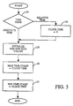
- the program of FIG. 3 enters decision block 24 to determine the time mode chosen, relative time or absolute time. If the selection is relative time, wherein all min/max values are time stamped relative to the time when the min/max mode operation was initiated, the process enters block 26 wherein clock time is set to zero, or some other relative initialization value. Thereupon the process proceeds to block 28, initializing the minimum and maximum values in memory (setting them, for example, to be the currently measured value at the DMM inputs 12 of FIG. 1A and FIG.
- the process proceeds directly to initialize minimum and maximum values block 28 without clearing the clock time, ensuring that any future references to the clock time produce an absolute time value.
- the clock may comprise, for example, a time of day representation.
- the process continues with block 30 for setting the maximum time stamp equal to the current clock time and then to block 32 wherein the minimum time stamp is set equal to the clock time, after which the process ends.
- the minimum time stamp and maximum time stamp can be initialized with a value that indicates that no update of the minimum or maximum value has occurred since the start of min/max operation.
- the device proceeds with measuring and displaying the values provided at the DMM inputs 12 (FIGS. 1A and 1B).
- the microprocessor operates In accordance with the FIG. 4 flow chart of the update min/max information process 80 of FIG. 2.
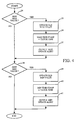
- the newly measured value 81 (FIG. 2) is examined at decision block 34 to determine if the value is a new maximum value, i.e., if the present measured value is greater than the previously stored, highest measured value. If the current measurement is a new maximum value, the process proceeds to block 35 to "update old max value" wherein the currently measured value replaces the previously stored maximum value.
- process block 36 in order to record the time when the maximum occurred the maximum time stamp is set to the current value of clock time, and the "output max update alert" step (block 37) directs the microprocessor to send a signal to alert output module 21 (FIG. 1B) for notifying the meter user that a new maximum value has been recorded.
- decision block 38 examining the measured value determines if a new minimum value has been measured, i.e., if the current value is less than the previously lowest measured and stored value. If the value is not a new minimum, this process ends, but if the measurement is a new minimum value, block 39 is executed wherein the presently measured value updates the stored minimum value, while in block 40, the minimum time stamp is set to the current clock time.
- the "output min update alert" step 41 directs the microprocessor to signal output module 21 for generating an alert signal to the meter user that a new minimum value has been recorded.
- the generate max update alert step 37 and generate min update alert step 41 may comprise, for example, generation of audible tones through alert output 21 of FIG. 1B wherein the tones may differ depending upon which step is being executed to allow an operator to identify the particular alert condition. The process, having updated the maximum and minimum values and times, returns to await another periodic measurement cycle.
- FIG. 5 comprises a state diagram of the display minimum/maximum data process 82 of FIG. 2, in an embodiment of the present invention utilizing a single key on keypad 18 of FIGS. 1A and 1B to enable scrolling through the recorded data.
- the process starts by displaying the current measured value in block 42 (on display 22 of FIGS. 1A and 1B).
- the display state will remain at block 42 until an appropriate key (a scroll key) is pushed on keypad 18 (FIG. 1) whereupon the process will enter state block 44, for displaying the maximum measured value.
- the process displays (block 46) the maximum time stamp, showing either the absolute or relative time (depending upon which time mode was selected in accordance with FIG. 3).
- Still another key push will cause the display to enter state 48 wherein the minimum value is displayed.
- state 50 is entered whereupon the minimum time stamp is displayed for the point in time at which the minimum value was measured.
- Another key push will return the process to state 42 for displaying the current value.
- the meter operator can scroll the display through the current value and minimum/maximum values as well as times of measurements through use of a single key.
- the operator may abort the minimum/maximum display mode, for example, by operating the function selector to exit the minimum/maximum mode or by depressing and holding the scroll key for an extended period of time whereupon the process ends the display of min/max data.
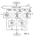
- FIG. 6 a state diagram for displaying minimum/maximum values and time stamps for a multikey system is illustrated as would be implemented when key pad 18 of FIGS. 1A and 1B is provided with multiple keys, each associated with a particular function.
- the process enters decision block 52 for determining which key has been pushed, and, if a current value key has been selected, the current value is displayed (block 54). If the maximum value key has been depressed, the maximum value appears (block 56). If the operator depresses the maximum time stamp key, the display maximum time stamp block 58 is entered whereby the maximum time stamp is shown.
- depressing the minimum value key will cause the process to enter block 60, display minimum value, and, finally, if the minimum time stamp key is depressed, the minimum time stamp value is provided (block 62). As with blocks 54, 56, 58 and 60, the process is then completed.
- the currently measured value (in this example DC voltage) is displayed at 88, e.g. 3.65 volts.
- Unit annunciator 89 indicates that the current value is a DC voltage, while if other measurement units were used, a different unit annunciator would appear (AC volts, ohms, etc.).
- the display at 90 next appears, showing, for example, 3.88 volts DC, as the maximum measured voltage identified by the "MAX" symbol 92 at the lower center, the unit annunciator 89 also remaining on the display.
- a subsequent depression of the key results in the display 94, "00:37", showing, for this example, that the maximum value occurred 0 hours and 37 minutes after the monitoring began (assuming a relative time mode).
- the "MAX” indicator is still shown, to denote that the time stamp is associated with the maximum value.
- Still another key actuation will result in the display 96 of the minimum voltage, in this case 3.5 volts, while the "MAX” symbol extinguishes and the minimum indicator 98, comprising the word "MIN" in the illustrated embodiment, appears in the lower left hand corner.
- Unit annunciator 89 reappears to denote the displayed units.
- FIG. 7B illustrates the time stamp generated in the relative time mode when the time stamp value is out of the range of the display.
- Display 102 shows an "0:L" (overload).
- the "MAX” indicator 92 is also illuminated in FIG. 7B to denote that the display is the maximum value time stamp. If the out of range time value were associated with a minimum value, the "MIN" indicator 98 would appear instead.
- the min/max function may also be performed without recording the time of occurrence if the operator so desires.
Landscapes
- Physics & Mathematics (AREA)
- General Physics & Mathematics (AREA)
- Measuring Instrument Details And Bridges, And Automatic Balancing Devices (AREA)
- Measurement Of Current Or Voltage (AREA)
Description
- The present invention relates to multimeters and particularly to multimeters for recording and displaying minimum and maximum readings as well as the time of occurrence of such readings.
- Technicians repairing and debugging electrical equipment often wish to measure minimum and maximum values of voltage, resistance and the like at various points within a circuit or device under test. In addition it is helpful to know the time when a minimum or maximum value took place. Heretofore it has been necessary to observe the measurement instrument and manually record the minimum and maximum values as well as the times at which those values occurred. Such a method is undesirable in that the technician must remain at the location of the measuring instrument and monitor the operation thereof. Further, if the minimum or maximum event occurs for a short time span, it might pass unobserved. Thus the technician may miss the event while away from the work area or during a moment of inattention.
- The minimum or maximum event may take place on an irregular basis or after an extended period of equipment operation, requiring long, tedious observation stints while awaiting the event, at which time the technician is hindered from undertaking other tasks and more efficiently using his time. The technician may also wish to determine minimum/maximum event times relative to a second event, e.g. initial device power-up. Heretofore, such a determination has required recording starting time and subsequently manually calculating relative elapsed time after noting the times for minimum/maximum events. It would be desirable to determine minimum and maximum values and the times when the minimum and maximum values were measured, without requiring constant observation and manual recording.
- An alternate method of recording minimum/maximum event information involves using a data logging device. However, typical data logging devices have drawbacks. Currently available devices require setting event trigger values, and do not record and time stamp data unless the measured parameter exceeds a preset event trigger limit. This limitation requires an operator to have some knowledge of the approximate limit values before beginning measurement, often a difficult task when troubleshooting equipment problems of unknown origin. Improperly choosing a limit can result in no meaningful data being obtained if the limit is too high. If too low, then too much data is recorded. Further, data logging devices are relatively large and cumbersome and it would be desirable to provide a handheld device capable of recording maximum and minimum values as well as the times when those values occurred.
- German Patent Application DE-A-3 837 592 describes a measuring device in which maximum and minimum values of a physical quantity can be displayed and stored in conjunction with the date and relevant time for each value. Furthermore, an alarm function is provided for alerting a user when a pre-set maximum value or a pre-set minimum value of the physical quantity has been reached.
- German Patent Application DE-A-3 519 908 describes a device for displaying and monitoring system pressure. Whenever the value of the pressure is below a pre-set minimum value or above a pre-set maximum value, a user is alerted.
- It would be desirable to provide:
an improved time stamp method and apparatus for indicating when an event occurred;
an improved multimeter for recording and displaying minimum measured value, maximum measured value and their times of measurement;
an improved method and apparatus for displaying measured values, times of measurement and current measurement values; and
to provide a time stamping measurement device in a hand-held package. - In accordance with a first aspect of the present invention there is provided a measurement device comprising:
measurement means for acquiring a signal and for producing a first measurement value representative of the signal;
means for comparing said first value with a stored second value representative of a maximum which is defined by previously measured values and to replace said stored second value with said first value if said first value is greater than said second value, and for comparing said first value with a stored third value representative of a minimum which is defined by previously measured values and to replace said stored third value with said first value if said first value is less than said third value;
means for storing a fourth value representative of the time at which the signal associated with said first value that replaced said second stored value was acquired by said measurement means, and for storing a fifth value representative of the time at which the signal associated with said first value that replaced said third stored value was acquired by said measurement means; and
alert means for providing an indication in response to said first value;
characterised in that said alert means is responsive to said comparing means for indicating that said second value has been replaced with said first value and for indicating that said third value has been replaced with said first value. - In accordance with a second aspect of the present invention there is provided a method for operating a measurement device comprising the steps of:
acquiring a measurement value from a received signal;
determining the time at which said measurement value was acquired;
determining if said acquired measurement value is less than a previously measured and stored minimum value and, if so, storing said acquired value as a minimum measured value and storing the time at which said minimum measured value was acquired; and
determining if said acquired measured value is greater than a previously measured and stored maximum value and, if so, storing said acquired value as a maximum measured value, and storing the time at which said maximum measured value was acquired;
characterised by the steps of:
generating an alert signal for indicating that a maximum value has been stored; and
generating an alert signal for indicating that a minimum value has been stored. - A preferred embodiment of the present invention comprises an instrument such as a digital multimeter including analog data acquisition circuitry for converting measured values into digital data for interpretation and storage by a microprocessor. The multimeter has the capability of storing minimum and maximum measured values as well as the capability of displaying measured minimum, maximum and current values. The system is also adapted to record the time when a minimum or maximum event occurs. The time value can be either relative to a particular time or can be the absolute time (e.g. time of day) when the event in question took place.
- The instrument may be advantageously arranged to display minimum and maximum values in a sequential manner by scrolling a display through minimum value, time measured, maximum value, time measured and current measured value. An alert signal indicates when an update either the minimum or maximum value takes place.
- The organisation and method of operation of the present invention, together with further advantages may best be understood by reference to the following description taken in conjunction with the accompanying drawings wherein like reference characters refer to like elements.
-
- FIG. 1A is a perspective view of a handheld digital multimeter according to the present invention;
- FIG. 1B is a block diagram of a digital multimeter in accordance with the present invention;
- FIG. 2 is a data flow and control flow diagram for min/max time stamping according to the present invention;
- FIG. 3 is a flow chart of the start minimum/maximum operation process of a multimeter in accordance with the present invention;
- FIG. 4 is a flow chart of the update min/max information process in accordance with the present invention;
- FIG. 5 is a state diagram for the displaying of min/max data process for a single key scrolling embodiment of the present invention;
- FIG. 6 is a state diagram for the display min/max data process in the case of a multiple key embodiment of the present invention;
- FIG. 7A illustrates an example of a min/max time stamp display sequence in accordance with the present invention; and
- FIG. 7B illustrates an example of the display of a relative time out of range condition.
- Referring now to FIG. 1A, a perspective view of a hand held digital multimeter in accordance with the present invention,
multimeter 10 is provided withinput connectors 12 extending to an end of the meter case and which connect to test leads (not illustrated) for coupling the meter to a device under test. Centrally disposed along the top face of the meter is akey pad 18, comprising four keys in the illustrated embodiment. Afunction selector 20, which serves to allow the meter operator to choose various meter functions, is installed on the top face of the meter adjacent the key pad and comprises, for example, a multiple position slide switch. On the opposite side of the key pad from the function selector isdisplay 22, suitably comprising a liquid crystal display. - Referring to FIG. 1B, comprising a block diagram of a
digital multimeter 10 in accordance with the present invention,multimeter inputs 12 are coupled to input circuitry and A toD converter 14 that generates a digital representation of the analog signal presented at the inputs.Microprocessor 16, which reads the digital output ofconverter 14 for processing, is provided with random access memory, read only memory and clock circuitry. The microprocessor also receives input fromkeypad 18 as well as fromfunction selector 20, operative to control various functions of the multimeter.Microprocessor 16 supplies data to alertoutput module 21 for generating an alert signal during operation wherein this alert signal may comprise an audible tone. The microprocessor further supplies display data to display 22 in order to provide visual readout of measurement values and times.Power supply 23 includingbattery 25 supplies power to the various circuits of the multimeter. In operation, the multimeter performs measurements on a programmed, cyclical basis, periodically sampling signals at the input and converting them from analog to digital form for processing and display. - Referring now to FIG. 2, comprising a combined data flow and control diagram for min/max time stamp operation of the microprocessor, a timer interrupt 70 occurs at regular intervals and is received by
update clock process 72. The update clock process provides the current time for theclock time 74 and does so by retrieving and storing clock times in relation to occurrence of the timer interrupt.Clock time 74 may, however, be set initially by the start min/max operation process 76, andprocess 76 can also set min/max values andtime stamps 78. Min/max values andtime stamps 78 store the measured minimum and maximum values together with the clock times when those values were measured. Update min/max information process 80 receivesclock time 74 as well as measured value 81 (the current value supplied by input circuitry and A/D 14) and provides measurement values and clock times for min/max values andtime stamps 78. These min/max values and time stamps also supply the display min/max data process 82 which is responsive tokey push data 84 and generatesdisplay data output 86 for presentation ondisplay 22 in FIG. 1A and FIG. 1B. - Referring now to FIG. 3, comprising a flow chart for the start min/
max operation process 76 of FIG. 2, the initialization of the min/max time stamping will be described. Min/max mode is selected, for example, by operation ofkeypad 18. Upon selection of the min/max mode, the program of FIG. 3 entersdecision block 24 to determine the time mode chosen, relative time or absolute time. If the selection is relative time, wherein all min/max values are time stamped relative to the time when the min/max mode operation was initiated, the process enters block 26 wherein clock time is set to zero, or some other relative initialization value. Thereupon the process proceeds to block 28, initializing the minimum and maximum values in memory (setting them, for example, to be the currently measured value at theDMM inputs 12 of FIG. 1A and FIG. 1B). However, if atdecision block 24 the time mode is absolute time mode, the process proceeds directly to initialize minimum and maximum values block 28 without clearing the clock time, ensuring that any future references to the clock time produce an absolute time value. The clock may comprise, for example, a time of day representation. After initializing minimum and maximum values, the process continues withblock 30 for setting the maximum time stamp equal to the current clock time and then to block 32 wherein the minimum time stamp is set equal to the clock time, after which the process ends. As an alternative, in an absolute time mode, the minimum time stamp and maximum time stamp can be initialized with a value that indicates that no update of the minimum or maximum value has occurred since the start of min/max operation. - Once initialization is complete, the device proceeds with measuring and displaying the values provided at the DMM inputs 12 (FIGS. 1A and 1B). During each measurement cycle, the microprocessor operates In accordance with the FIG. 4 flow chart of the update min/
max information process 80 of FIG. 2. The newly measured value 81 (FIG. 2) is examined atdecision block 34 to determine if the value is a new maximum value, i.e., if the present measured value is greater than the previously stored, highest measured value. If the current measurement is a new maximum value, the process proceeds to block 35 to "update old max value" wherein the currently measured value replaces the previously stored maximum value. Next, inprocess block 36, in order to record the time when the maximum occurred the maximum time stamp is set to the current value of clock time, and the "output max update alert" step (block 37) directs the microprocessor to send a signal to alert output module 21 (FIG. 1B) for notifying the meter user that a new maximum value has been recorded. - When the update has occurred, the process continues with
decision block 38. (If the result of the test indecision block 34 was that a new maximum value had not been measured, then the process proceeds directly todecision block 38 without executingsteps decision block 38, examining the measured value determines if a new minimum value has been measured, i.e., if the current value is less than the previously lowest measured and stored value. If the value is not a new minimum, this process ends, but if the measurement is a new minimum value, block 39 is executed wherein the presently measured value updates the stored minimum value, while inblock 40, the minimum time stamp is set to the current clock time. Again, in a manner similar to the case of a new maximum value, the "output min update alert"step 41 directs the microprocessor to signaloutput module 21 for generating an alert signal to the meter user that a new minimum value has been recorded. The generate max updatealert step 37 and generate minupdate alert step 41 may comprise, for example, generation of audible tones throughalert output 21 of FIG. 1B wherein the tones may differ depending upon which step is being executed to allow an operator to identify the particular alert condition. The process, having updated the maximum and minimum values and times, returns to await another periodic measurement cycle. - FIG. 5 comprises a state diagram of the display minimum/
maximum data process 82 of FIG. 2, in an embodiment of the present invention utilizing a single key onkeypad 18 of FIGS. 1A and 1B to enable scrolling through the recorded data. The process starts by displaying the current measured value in block 42 (ondisplay 22 of FIGS. 1A and 1B). The display state will remain atblock 42 until an appropriate key (a scroll key) is pushed on keypad 18 (FIG. 1) whereupon the process will enterstate block 44, for displaying the maximum measured value. After another press of the scroll key, the process then displays (block 46) the maximum time stamp, showing either the absolute or relative time (depending upon which time mode was selected in accordance with FIG. 3). Still another key push will cause the display to enter state 48 wherein the minimum value is displayed. When the key is pushed again,state 50 is entered whereupon the minimum time stamp is displayed for the point in time at which the minimum value was measured. Another key push will return the process to state 42 for displaying the current value. In this manner, the meter operator can scroll the display through the current value and minimum/maximum values as well as times of measurements through use of a single key. At any state of the display, the operator may abort the minimum/maximum display mode, for example, by operating the function selector to exit the minimum/maximum mode or by depressing and holding the scroll key for an extended period of time whereupon the process ends the display of min/max data. - Referring now to FIG. 6, a state diagram for displaying minimum/maximum values and time stamps for a multikey system is illustrated as would be implemented when
key pad 18 of FIGS. 1A and 1B is provided with multiple keys, each associated with a particular function. The process entersdecision block 52 for determining which key has been pushed, and, if a current value key has been selected, the current value is displayed (block 54). If the maximum value key has been depressed, the maximum value appears (block 56). If the operator depresses the maximum time stamp key, the display maximumtime stamp block 58 is entered whereby the maximum time stamp is shown. Similarly, depressing the minimum value key will cause the process to enterblock 60, display minimum value, and, finally, if the minimum time stamp key is depressed, the minimum time stamp value is provided (block 62). As withblocks - Referring now to FIG. 7A and FIG. 7B, illustrating configurations as may be generated on
display 22 of FIGS. 1A and 1B when using the method as discussed in conjunction with FIG. 5, the currently measured value (in this example DC voltage) is displayed at 88, e.g. 3.65 volts.Unit annunciator 89 indicates that the current value is a DC voltage, while if other measurement units were used, a different unit annunciator would appear (AC volts, ohms, etc.). When the operator presses the key, the display at 90 next appears, showing, for example, 3.88 volts DC, as the maximum measured voltage identified by the "MAX"symbol 92 at the lower center, theunit annunciator 89 also remaining on the display. A subsequent depression of the key results in thedisplay 94, "00:37", showing, for this example, that the maximum value occurred 0 hours and 37 minutes after the monitoring began (assuming a relative time mode). The "MAX" indicator is still shown, to denote that the time stamp is associated with the maximum value. Still another key actuation will result in thedisplay 96 of the minimum voltage, in this case 3.5 volts, while the "MAX" symbol extinguishes and theminimum indicator 98, comprising the word "MIN" in the illustrated embodiment, appears in the lower left hand corner.Unit annunciator 89 reappears to denote the displayed units. Depressing the key again will cause the unit annunciator to be extinguished, while providingdisplay 100, "19:42", which indicates that the minimum measured value occurred 19 hours and 42 minutes after the monitoring began, assuming relative time mode. (Alternatively the absolute time mode could indicate, for example, that the minimum took place at 7:42 p.m.). Pressing the key again cycles the display back to 88, showing the currently measured value and simultaneously extinguishing theminimum indicator 92. Leading zeros are not suppressed for the time mode. Conversely, the displays at 88, 90 and 96 have leading zero suppression, and carry a decimal point between the appropriate digits which does not blink, therefore helping to distinguish between time values (where the colon blinks) and the measured value. FIG. 7B illustrates the time stamp generated in the relative time mode when the time stamp value is out of the range of the display.Display 102 shows an "0:L" (overload). The "MAX"indicator 92 is also illuminated in FIG. 7B to denote that the display is the maximum value time stamp. If the out of range time value were associated with a minimum value, the "MIN"indicator 98 would appear instead. - Although the foregoing description describes the min/max measurement function with time stamping, the min/max function may also be performed without recording the time of occurrence if the operator so desires.
- While preferred embodiments of the present invention have been shown and described, it will be apparent to those skilled in the art that many changes and modifications may be made without departing from the invention in its broader aspects. The appended claims are therefore intended to cover all such changes and modifications as fall within the scope of the invention.
Claims (18)
- A measurement device (10) comprising:
measurement means for acquiring a signal and for producing a first measurement value representative of the signal;
means (16) for comparing said first value with a stored second value representative of a maximum which is defined by previously measured values and to replace said stored second value with said first value if said first value is greater than said second value, and for comparing said first value with a stored third value representative of a minimum which is defined by previously measured values and to replace said stored third value with said first value if said first value is less than said third value;
means for storing a fourth value representative of the time at which the signal associated with said first value that replaced said second stored value was acquired by said measurement means, and for storing a fifth value representative of the time at which the signal associated with said first value that replaced said third stored value was acquired by said measurement means; and
alert means (21) for providing an indication in response to said first value;
characterised in that said alert means (21) is responsive to said comparing means for indicating that said second value has been replaced with said first value and for indicating that said third value has been replaced with said first value. - A measurement device according to claim 1 further comprising display means (22) for displaying said first, second, third, fourth and fifth values.
- A measurement device according to claim 1 or claim 2, wherein said alert means (21) comprises audio alert means.
- A measurement device as claimed in any preceding claim, further comprising:
means (18) for selectively operating said device in a relative time measurement mode and an absolute time measurement mode. - A measurement device in accordance with any one of claims 1 to 4, further comprising clock means for providing time values for recording times when said minimum and maximum values are recorded.
- A measurement device in accordance with any one of claims 1 to 5, further comprising means (18) for enabling selection of a minimum/maximum measurement mode.
- A measurement device as claimed in any preceding claim, wherein said first, second and third values are digital values and said comparing means comprises microprocessor means (16).
- A measurement device as claimed in any preceding claim, wherein said measurement means comprises an analog-to-digital converter (14).
- A hand-held digital multimeter comprising a measurement device as claimed in any preceding claim.
- A method for operating a measurement device (10) comprising the steps of:
acquiring a measurement value from a received signal;
determining the time at which said measurement value was acquired;
determining if said acquired measurement value is less than a previously measured and stored minimum value and, if so, storing said acquired value as a minimum measured value and storing the time at which said minimum measured value was acquired; and
determining if said acquired measured value is greater than a previously measured and stored maximum value and, if so, storing said acquired value as a maximum measured value, and storing the time at which said maximum measured value was acquired;
characterised by the steps of:
generating an alert signal for indicating that a maximum value has been stored; and
generating an alert signal for indicating that a minimum value has been stored. - A method as claimed in claim 10, further comprising:
selecting whether said time at which said minimum measured value was acquired and said time at which said maximum measured value was acquired are relative to a specified time or are absolute time. - A method according to claim 11 wherein said time at which said minimum measured value was acquired and said time at which said maximum measured value was acquired are relative to a starting time.
- A method according to claim 11 or claim 12, wherein said time at which said minimum measured value was acquired and said time at which said maximum measured value was acquired are absolute time values.
- A method according to any one of claims 10 to 13, wherein said alert signal comprises an audio alert signal.
- A method according to any one of claims 10 to 14, further comprising the steps of displaying said stored minimum measured value, displaying said stored time at which said minimum measured value was taken, displaying said stored maximum measured value and displaying said stored time at which said maximum measured value was taken.
- A method according to claim 15, wherein said displaying steps are performed in a sequential manner, control of said sequential manner being responsive to a display change signal.
- A method according to claim 15, wherein the order of said display steps is determined by a display selection signal.
- A method according to any one of claims 10 to 17, wherein said alert signal for indicating that a minimum value has been stored comprises a first audio alert signal and wherein said alert signal for indicating that a maximum value has been stored comprises a second audio alert signal.
Applications Claiming Priority (2)
| Application Number | Priority Date | Filing Date | Title |
|---|---|---|---|
| US66635491A | 1991-03-08 | 1991-03-08 | |
| US666354 | 1991-03-08 |
Publications (2)
| Publication Number | Publication Date |
|---|---|
| EP0503185A1 EP0503185A1 (en) | 1992-09-16 |
| EP0503185B1 true EP0503185B1 (en) | 1995-12-27 |
Family
ID=24673846
Family Applications (1)
| Application Number | Title | Priority Date | Filing Date |
|---|---|---|---|
| EP91305480A Expired - Lifetime EP0503185B1 (en) | 1991-03-08 | 1991-06-18 | Multimeter having min/max time stamp |
Country Status (5)
| Country | Link |
|---|---|
| US (1) | US5432706A (en) |
| EP (1) | EP0503185B1 (en) |
| JP (1) | JP2774983B2 (en) |
| KR (1) | KR920018486A (en) |
| DE (1) | DE69115880T2 (en) |
Cited By (1)
| Publication number | Priority date | Publication date | Assignee | Title |
|---|---|---|---|---|
| DE10036664A1 (en) * | 2000-07-26 | 2002-02-14 | Metrawatt Gmbh Gossen | Digital multimeter for measuring current, voltage, resistance and capacitance, has handle that is activated to switch multimeter between multimeter functions and current tong test instrument function |
Families Citing this family (13)
| Publication number | Priority date | Publication date | Assignee | Title |
|---|---|---|---|---|
| US20030198135A1 (en) * | 2002-04-19 | 2003-10-23 | Beatty John S. | Material temperature exposure timer apparatus and method |
| JP2006319893A (en) * | 2005-05-16 | 2006-11-24 | Sumitomo Electric Ind Ltd | Optical module |
| US8456153B2 (en) * | 2007-08-14 | 2013-06-04 | Fluke Corporation | Digital multimeter having improved recording functionality |
| US9347975B2 (en) | 2007-08-14 | 2016-05-24 | Fluke Corporation | Auto-numbering of measurements in digital multimeter |
| US8269481B2 (en) * | 2007-08-14 | 2012-09-18 | Fluke Corporation | Automatic capture and storage of measurements in digital multimeter |
| US8198884B2 (en) * | 2007-08-14 | 2012-06-12 | Fluke Corporation | Mini-measurement display for digital multimeter |
| US8456152B2 (en) * | 2007-08-14 | 2013-06-04 | Fluke Corporation | Digital multimeter with context-sensitive explanatory information |
| US8076926B2 (en) * | 2007-08-14 | 2011-12-13 | Fluke Corporation | Rotary switch memory for digital multimeter |
| USD639191S1 (en) | 2008-10-16 | 2011-06-07 | Fluke Corporation | Process multimeter |
| USD617225S1 (en) * | 2009-04-14 | 2010-06-08 | Fluke Corporation | Process multimeter |
| JP2011165154A (en) * | 2010-02-05 | 2011-08-25 | M-System Co Ltd | Measured value management system using measuring equipment with display |
| JP5654825B2 (en) * | 2010-10-05 | 2015-01-14 | 日置電機株式会社 | Insulation resistance measuring device |
| US9568504B2 (en) | 2013-03-15 | 2017-02-14 | Milwaukee Electric Tool Corporation | Digital multi-meter |
Family Cites Families (17)
| Publication number | Priority date | Publication date | Assignee | Title |
|---|---|---|---|---|
| US3631410A (en) * | 1969-11-03 | 1971-12-28 | Gen Motors Corp | Event recorder |
| JPS5280179A (en) * | 1975-12-26 | 1977-07-05 | Casio Comput Co Ltd | Digital measuring apparatus |
| FR2381313A2 (en) * | 1975-12-31 | 1978-09-15 | Labo Electronique Physique | SIGNAL RECORDING AND VIEWING |
| US4372692A (en) * | 1979-09-17 | 1983-02-08 | Trustees Of Dartmouth College | Electronic device to record temperatures and the time of occurrence |
| US4286465A (en) * | 1979-09-17 | 1981-09-01 | Trustees Of Dartmouth College | Electronic device to record temperatures and the time of occurrence |
| US4400783A (en) * | 1980-09-05 | 1983-08-23 | Westinghouse Electric Corp. | Event-logging system |
| DE3328540A1 (en) * | 1983-08-06 | 1985-02-14 | Robert Bosch Gmbh, 7000 Stuttgart | DEVICE FOR MEASURING TIME BETWEEN TWO EVENTS |
| DE3503443A1 (en) * | 1984-02-02 | 1985-08-08 | Sharp K.K., Osaka | CONTROL SYSTEM FOR DETERMINING THE CARD SPEED IN A CARD READER |
| DE3519908A1 (en) * | 1985-06-04 | 1986-12-04 | Hubert 5860 Iserlohn Droigk | Device for displaying and monitoring a system pressure |
| JPS62220813A (en) * | 1986-03-20 | 1987-09-29 | Shikoku Electric Power Co Inc | Digital automatic load state recording device for electric power |
| JPS62173066U (en) * | 1986-04-23 | 1987-11-04 | ||
| JPS6325568A (en) * | 1986-07-17 | 1988-02-03 | Kaize Denki Kk | Digital multimeter |
| JPS6454370A (en) * | 1987-08-26 | 1989-03-01 | Shiojiri Kogyo Kk | Digital multimeter with digital memory |
| JPH0230059U (en) * | 1988-08-19 | 1990-02-26 | ||
| DE3837592A1 (en) * | 1988-11-05 | 1990-05-10 | Nuechter Karl Bernhard | MEASURING DEVICE |
| JPH02129561A (en) * | 1988-11-09 | 1990-05-17 | Matsushita Electric Ind Co Ltd | Display device for measurement values of multiple circuits |
| US5155693A (en) * | 1990-09-05 | 1992-10-13 | Hewlett-Packard Company | Self documenting record of instrument activity and error messages stamped with date and time of occurrence |
-
1991
- 1991-06-18 EP EP91305480A patent/EP0503185B1/en not_active Expired - Lifetime
- 1991-06-18 DE DE69115880T patent/DE69115880T2/en not_active Expired - Fee Related
- 1991-07-18 KR KR1019910012230A patent/KR920018486A/en not_active Ceased
- 1991-09-27 JP JP3276734A patent/JP2774983B2/en not_active Expired - Lifetime
-
1993
- 1993-01-05 US US08/000,811 patent/US5432706A/en not_active Expired - Fee Related
Cited By (1)
| Publication number | Priority date | Publication date | Assignee | Title |
|---|---|---|---|---|
| DE10036664A1 (en) * | 2000-07-26 | 2002-02-14 | Metrawatt Gmbh Gossen | Digital multimeter for measuring current, voltage, resistance and capacitance, has handle that is activated to switch multimeter between multimeter functions and current tong test instrument function |
Also Published As
| Publication number | Publication date |
|---|---|
| EP0503185A1 (en) | 1992-09-16 |
| US5432706A (en) | 1995-07-11 |
| DE69115880T2 (en) | 1996-05-15 |
| DE69115880D1 (en) | 1996-02-08 |
| JP2774983B2 (en) | 1998-07-09 |
| KR920018486A (en) | 1992-10-22 |
| JPH05249147A (en) | 1993-09-28 |
Similar Documents
| Publication | Publication Date | Title |
|---|---|---|
| US5432706A (en) | Multimeter having min/max time stamp | |
| US4743831A (en) | Apparatus and method for indicating remaining battery life in a battery powered device | |
| US4195348A (en) | Combined electronic digital scale and calculator storing selectable programs | |
| US4800336A (en) | Battery level indicator supplying data from a memory to a display in a power-off state | |
| US5757357A (en) | Method and system for displaying digital data with zoom capability | |
| US4864512A (en) | Measurement apparatus with plural displays of measured parameter and selectable function thereof | |
| JPS6231306B2 (en) | ||
| EP0156548B1 (en) | Data display apparatus | |
| US4825143A (en) | Digital meter automatic off power supply circuit | |
| US4255803A (en) | Electronic timepiece equipped with alarm function | |
| JP3133109B2 (en) | Digital Multimeters | |
| CA1099410A (en) | Data acquisition and display device | |
| GB2203252A (en) | Electricity consumption cost indicator | |
| EP0696740A2 (en) | Multimeter-like user interface for a graphical instrument | |
| US5122996A (en) | Real-time, uninterrupted time-interval to voltage converter | |
| EP0318549B1 (en) | Test meters | |
| JP2000214196A (en) | Control method of insulation resistance meter | |
| JPS5835605A (en) | Instrumentation controller | |
| JP2723126B2 (en) | measuring equipment | |
| JP2814166B2 (en) | Measuring instrument | |
| KR100340876B1 (en) | Television receiver with frequency measure and frequency measure method thereof | |
| EP0581426B1 (en) | Autoranging instrument having selectable range setting restrictions | |
| JP2909352B2 (en) | Digital measuring instrument | |
| CA1288818C (en) | Test meters | |
| AU632375B2 (en) | Portable shock absorber test instrument |
Legal Events
| Date | Code | Title | Description |
|---|---|---|---|
| PUAI | Public reference made under article 153(3) epc to a published international application that has entered the european phase |
Free format text: ORIGINAL CODE: 0009012 |
|
| AK | Designated contracting states |
Kind code of ref document: A1 Designated state(s): DE FR GB NL |
|
| 17P | Request for examination filed |
Effective date: 19921013 |
|
| 17Q | First examination report despatched |
Effective date: 19931206 |
|
| GRAA | (expected) grant |
Free format text: ORIGINAL CODE: 0009210 |
|
| AK | Designated contracting states |
Kind code of ref document: B1 Designated state(s): DE FR GB NL |
|
| PG25 | Lapsed in a contracting state [announced via postgrant information from national office to epo] |
Ref country code: NL Free format text: LAPSE BECAUSE OF FAILURE TO SUBMIT A TRANSLATION OF THE DESCRIPTION OR TO PAY THE FEE WITHIN THE PRESCRIBED TIME-LIMIT Effective date: 19951227 |
|
| REF | Corresponds to: |
Ref document number: 69115880 Country of ref document: DE Date of ref document: 19960208 |
|
| ET | Fr: translation filed | ||
| NLV1 | Nl: lapsed or annulled due to failure to fulfill the requirements of art. 29p and 29m of the patents act | ||
| PLBE | No opposition filed within time limit |
Free format text: ORIGINAL CODE: 0009261 |
|
| STAA | Information on the status of an ep patent application or granted ep patent |
Free format text: STATUS: NO OPPOSITION FILED WITHIN TIME LIMIT |
|
| 26N | No opposition filed | ||
| REG | Reference to a national code |
Ref country code: GB Ref legal event code: IF02 |
|
| PGFP | Annual fee paid to national office [announced via postgrant information from national office to epo] |
Ref country code: GB Payment date: 20040609 Year of fee payment: 14 |
|
| PGFP | Annual fee paid to national office [announced via postgrant information from national office to epo] |
Ref country code: FR Payment date: 20040618 Year of fee payment: 14 |
|
| PGFP | Annual fee paid to national office [announced via postgrant information from national office to epo] |
Ref country code: DE Payment date: 20040802 Year of fee payment: 14 |
|
| PG25 | Lapsed in a contracting state [announced via postgrant information from national office to epo] |
Ref country code: GB Free format text: LAPSE BECAUSE OF NON-PAYMENT OF DUE FEES Effective date: 20050618 |
|
| PG25 | Lapsed in a contracting state [announced via postgrant information from national office to epo] |
Ref country code: DE Free format text: LAPSE BECAUSE OF NON-PAYMENT OF DUE FEES Effective date: 20060103 |
|
| PG25 | Lapsed in a contracting state [announced via postgrant information from national office to epo] |
Ref country code: FR Free format text: LAPSE BECAUSE OF NON-PAYMENT OF DUE FEES Effective date: 20060228 |
|
| GBPC | Gb: european patent ceased through non-payment of renewal fee |
Effective date: 20050618 |
|
| REG | Reference to a national code |
Ref country code: FR Ref legal event code: ST Effective date: 20060228 |