EP0501630B1 - Casing hanger seal assembly - Google Patents
Casing hanger seal assembly Download PDFInfo
- Publication number
- EP0501630B1 EP0501630B1 EP92301151A EP92301151A EP0501630B1 EP 0501630 B1 EP0501630 B1 EP 0501630B1 EP 92301151 A EP92301151 A EP 92301151A EP 92301151 A EP92301151 A EP 92301151A EP 0501630 B1 EP0501630 B1 EP 0501630B1
- Authority
- EP
- European Patent Office
- Prior art keywords
- sealing
- lips
- housing
- sealing surface
- interior
- Prior art date
- Legal status (The legal status is an assumption and is not a legal conclusion. Google has not performed a legal analysis and makes no representation as to the accuracy of the status listed.)
- Expired - Lifetime
Links
Images




Classifications
-
- E—FIXED CONSTRUCTIONS
- E21—EARTH OR ROCK DRILLING; MINING
- E21B—EARTH OR ROCK DRILLING; OBTAINING OIL, GAS, WATER, SOLUBLE OR MELTABLE MATERIALS OR A SLURRY OF MINERALS FROM WELLS
- E21B33/00—Sealing or packing boreholes or wells
- E21B33/02—Surface sealing or packing
- E21B33/03—Well heads; Setting-up thereof
-
- E—FIXED CONSTRUCTIONS
- E21—EARTH OR ROCK DRILLING; MINING
- E21B—EARTH OR ROCK DRILLING; OBTAINING OIL, GAS, WATER, SOLUBLE OR MELTABLE MATERIALS OR A SLURRY OF MINERALS FROM WELLS
- E21B33/00—Sealing or packing boreholes or wells
- E21B33/02—Surface sealing or packing
- E21B33/03—Well heads; Setting-up thereof
- E21B33/04—Casing heads; Suspending casings or tubings in well heads
-
- E—FIXED CONSTRUCTIONS
- E21—EARTH OR ROCK DRILLING; MINING
- E21B—EARTH OR ROCK DRILLING; OBTAINING OIL, GAS, WATER, SOLUBLE OR MELTABLE MATERIALS OR A SLURRY OF MINERALS FROM WELLS
- E21B2200/00—Special features related to earth drilling for obtaining oil, gas or water
- E21B2200/01—Sealings characterised by their shape
Definitions
- the present invention relates to an improved wellhead structure which is particularly adapted to subsea wells.
- Such structure includes a wellhead housing and an improved hanger and seal assembly which can be landed and set in a single trip.
- Prior to the present invention many efforts have been made to provide a satisfactory hanger and seal assembly which allows the landing of the hanger, cementing and the setting of the seal in the annulus between the exterior of the hanger and the interior of the housing.
- An object of the present invention is to provide an improved hanger seal assembly for use within a wellhead housing with improved metal to metal sealing against the inner and outer surfaces of the hanger housing annulus and which protects the seal assembly sealing surfaces from damage during running.
- US-4823871 discloses a metal to metal sealing assembly for sealing between the interior sealing surface of a well housing and the exterior sealing surface of a hanger landed within the well housing, the sealing assembly comprising an annular seal body having an outer seal lip, and a plurality of inner ridges; and energising means for engaging the outer seal lip and urging it outwardly to position the seal lip in sealing engagement with the interior sealing surface of the housing, and, according to the present invention, such an assembly is characterised by the outer seal lip having a first sealing surface and a second protecting surface with the second protecting surface having a larger free diameter than the diameter of the first sealing surface whereby any engagement with the interior surface of the well housing during running occurs at the second protecting surface such that the first sealing surface is protected from being scratched or otherwise damaged by such contact.
- the hanger is landed within the well housing before the seal assembly is moved into sealing position between the housing and the hanger.
- the seal assembly is lowered into sealing position between the external hanger sealing surface which is defined on the interior of the well housing and is spaced from the internal housing sealing surface and includes a seal body having external metal sealing lips diverging outward but having an initial free diameter less than the diameter of the housing internal sealing surface and internal metal sealing surfaces on the inner surface of the seal body having a free diameter smaller than the diameter of the hanger external sealing surface, a lower energizer ring movably connected to the seal body and having an upstanding rim which stores the force created by its engaging and moving the lower outer sealing lip to its set position, an upper energizer ring movably connected to the seal body and having a depending rim which stores the force created by its engaging and moving the upper lip to its set position.
- the lower outer sealing lip includes a first lower sealing surface and a second protecting surface spaced thereabove.
- the upper sealing lip is the mirror image of the lower sealing lip and includes a first outer sealing surface and a second protecting surface spaced thereabove.
- the second protecting surfaces have larger diameters than the first sealing surfaces so that if the sealing lip comes into contact with the housing through which it is passing the first sealing surfaces do not come into contact with the inner surface of the housing and are thereby protected against scratches and other damage during running.
- the sealing lips are moved into set position the first sealing surfaces are moved into sealing engagement with the inner surface of the surrounding housing. Additionally, the surfaces of the lips which may come into contact with the interior of the housing are provided with a coating of a soft, scratch healing material, such as silver plating.
- the interior projections which provide the interior sealing are spaced along the interior of the seal body by recesses which are either sufficiently deep to avoid problems with liquids trapped therein during setting or have a liquid exclusion material therein.
- Means for securing or locking the seal assembly and the energizer rings in their set position is included and such securing means includes means for engaging within grooves on the exterior of the hanger and on the interior of the housing.
- some means for storing the force of the rip setting force and this may include the storing of both axial and radial forces generated for setting the sealing lips.
- FIGURE 1 is a sectional elevation view of a hanger landed within a well housing and the improved seal assembly of the present invention being in position for lowering into sealing position across the annulus between the hanger external sealing surface and the well housing internal sealing surface.
- FIGURE 2 is a partial sectional view illustrating the seal assembly in its landed and set position in the hanger-housing annulus.
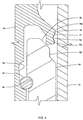
- FIGURE 3 is a detailed partial sectional view of the seal assembly of the present invention in its unset position.
- FIGURE 4 is a partial enlarged sectional view of the lower seal lip and the energizing ring as shown in FIGURE 3.
- FIGURE 5 is a detailed partial sectional view of the seal assembly shown in FIGURE 3 after it has been moved to its set position.
- FIGURE 6 is a partial enlarged sectional view of the lower seal lip and its energizing ring as shown in FIGURE 5.
- Improved seal assembly 10 of the present invention is illustrated while being lowered within well housing 12 and into annulus 14 between the interior of well housing 12 and the exterior of hanger 16 which has been landed within well housing 12.
- hangers 16A and 16B have previously been landed within housing 12 and their respective seal assemblies 10A and 10B have been landed and energized in the respective annuli 14A and 14B.
- Seal assembly 10 is supported from setting assembly 18 and setting assembly 18 is supported on a suitable tool (not shown) which can move the setting assembly 18 after landing into its set position as hereinafter described.
- Seal assembly 10 includes annular body 20, lower energizer ring 22, and upper energizer ring 24 as shown in FIGURES 2 and 3.
- Lower energizer ring 22 is movably attached to lower rim 26 of body 20 by split ring 28 which is positioned in groove 30 on the interior of energizer ring 22 and in elongated groove 32 in the exterior of lower body rim 26. This allows relative axial movement of energizer ring 22 with respect to body 20.
- Upper energizer ring 24 is movably attached to upper rim 34 of body 20 by split ring 36 which is positioned in groove 38 on the interior of energizer ring 24 and in elongated groove 40 on the exterior of upper body rim 34. This allows relative axial movement of energizer ring 24 with respect to body 20.
- Windows 42 are provided in upper energizer ring 24 with exterior latching ring 44 and interior split locking ring 46 positioned around ring 24 and biased inwardly and outwardly respectively.
- Wedge elements 48 are positioned within windows 42 immediately above exterior latching ring 44 during running and have a lower outer tapered surface 50 which coacts with upper inner tapered surface 52 on exterior latching ring 44.
- Ring 54 is positioned within energizer rim 66 of ring 24 and is secured by cap screws 56, or other suitable securing means, to wedge elements 48 as shown.
- Ring 54 includes lower tapered surface 50 which coacts with upper outer tapered surface 60 on split locking ring 46 as hereinafter explained.
- Ring 54 includes inner flange 62 and upper surface 64 which during running is at approximately the same level as upper surface 66 on upper energizer ring 24.
- seal body 20 includes upper annular lip 74 and lower annular lip 76.
- Upper annular lip 74 extends outwardly from the exterior of body 20 and then extends upwardly to a generally axial upward position.
- Lower annular lip 76 extends outwardly from the exterior of body 20 and then extends downwardly to a generally axial downward position.
- lips 74 and 76 include sealing lobes or surfaces 74a and 76a respectively at the outer extremity thereof as shown and protecting lobes or surfaces 74b and 76b respectively on the exterior surface of the lips 74 and 76 which extend generally axially and such surfaces 74b and 76b are spaced from surfaces 74a and 76a respectively by grooves 74c and 76c respectively.
- the diameter of protective surfaces 74b and 76b are larger in their free position than the outer diameter of sealing surfaces 74a and 76a as shown in FIGURES 3 and 4. In running position the exterior diameter of surfaces 74b and 76b is smaller than the inner diameter of housing 12.
- a coating 77 of a scratch healing soft metal is provided on the surfaces 74a, b and c and 76a, b and c.
- This coating is preferred to be with a metal such a silver or lead and a silver plating is preferred. With this coating any scratches on the sealing surfaces 74a or 76a will not interfere with the sealing engagement of such surfaces with the interior of the well housing 12 as shown in FIGURES 5 and 6.
- the coating 77 will be sufficiently soft so that when sealing surfaces 74a and 76a are forced into engagement with the housing interior, the metal of the coating will be sufficiently soft to flow into the scratch and avoid sealing problems.
- upper energizer ring 24 has its inner surface spaced slightly outward from the exterior surface of upper rim 34 and a lower tapered surface 78 which engages the inner surface of upper lip 74 during setting to move it radially outward to the set position in metal-to-metal sealing engagement with the interior surface of housing 12.
- Lower energizer ring 22 has its inner surface spaced slightly outward from the exterior surface of lower rim 26 and an upper tapered surface 80 which engages the inner surface of lower lip 76 during setting to move it radially outward to the set position in metal-to-metal sealing engagement with the interior surface of housing 12.
- the present invention uses a high yield strength steel for energizer rings 22 and 24 and uses a lower yield strength steel for upper and lower lips 74 and 76. This allows lips 74 and 76 to have sufficient malleability when forced against the interior of housing 12 to flow into the flaws and irregularities of such surface and ensure that there is complete metal-to-metal sealing. With the high yield strength energizer rings 22 and 24, they are subjected to a slight inward elastic deflection at their extremities as shown in FIGURE 6. This effectively stores the setting forces to ensure continued sealing of lips 74 and 76 against the interior of housing 12.
- the interior of body 20 includes a series of annular ridges 82 separated by grooves 84.
- the inner diameters of ridges 82 are smaller than the diameter of the exterior portion of hanger 16 against which seal body 20 is to engage and seal. Care should be taken with the depth of grooves 84 to avoid problems with the build-up of pressure in liquids trapped therein during setting so that the sealing loads of the ridges 82 are not reduced thereby. It is preferred that if the grooves 84 have a radial dimension of approximately 0.005" a water exclusion material or a volume compensating material should be provided in grooves 84 so that the water pressure developed therein does not interfere or lessen the sealing load of the ridges 82 against the exterior surface of hanger 16.
- the depth of grooves 84 be at least 0.040". This depth of grooves 84 is selected so that the compressibility of the volume of trapped fluid due to its bulk modulus is sufficient to prevent excessive pressure build-up due to flexing of the metal seal.
- Upper resilient sealing ring 86 is positioned in upper groove 88 and lower resilient sealing ring 90 is positioned in lower groove 92. Sealing rings 86 and 90 provide supplemental sealing between the interior of seal body 20 and the exterior of hanger 16.
Landscapes
- Geology (AREA)
- Life Sciences & Earth Sciences (AREA)
- Engineering & Computer Science (AREA)
- Mining & Mineral Resources (AREA)
- Geochemistry & Mineralogy (AREA)
- Fluid Mechanics (AREA)
- Environmental & Geological Engineering (AREA)
- General Life Sciences & Earth Sciences (AREA)
- Physics & Mathematics (AREA)
- Gasket Seals (AREA)
- Containers And Plastic Fillers For Packaging (AREA)
- Analysing Materials By The Use Of Radiation (AREA)
- Holders For Apparel And Elements Relating To Apparel (AREA)
- Lining Or Joining Of Plastics Or The Like (AREA)
- Buffer Packaging (AREA)
- Glass Compositions (AREA)
Abstract
Description
- The present invention relates to an improved wellhead structure which is particularly adapted to subsea wells. Such structure includes a wellhead housing and an improved hanger and seal assembly which can be landed and set in a single trip. Prior to the present invention many efforts have been made to provide a satisfactory hanger and seal assembly which allows the landing of the hanger, cementing and the setting of the seal in the annulus between the exterior of the hanger and the interior of the housing.
- An object of the present invention is to provide an improved hanger seal assembly for use within a wellhead housing with improved metal to metal sealing against the inner and outer surfaces of the hanger housing annulus and which protects the seal assembly sealing surfaces from damage during running.
- US-4823871 discloses a metal to metal sealing assembly for sealing between the interior sealing surface of a well housing and the exterior sealing surface of a hanger landed within the well housing, the sealing assembly comprising an annular seal body having an outer seal lip, and a plurality of inner ridges; and energising means for engaging the outer seal lip and urging it outwardly to position the seal lip in sealing engagement with the interior sealing surface of the housing, and, according to the present invention, such an assembly is characterised by the outer seal lip having a first sealing surface and a second protecting surface with the second protecting surface having a larger free diameter than the diameter of the first sealing surface whereby any engagement with the interior surface of the well housing during running occurs at the second protecting surface such that the first sealing surface is protected from being scratched or otherwise damaged by such contact.
- In a construction in accordance with the present invention, the hanger is landed within the well housing before the seal assembly is moved into sealing position between the housing and the hanger. The seal assembly is lowered into sealing position between the external hanger sealing surface which is defined on the interior of the well housing and is spaced from the internal housing sealing surface and includes a seal body having external metal sealing lips diverging outward but having an initial free diameter less than the diameter of the housing internal sealing surface and internal metal sealing surfaces on the inner surface of the seal body having a free diameter smaller than the diameter of the hanger external sealing surface, a lower energizer ring movably connected to the seal body and having an upstanding rim which stores the force created by its engaging and moving the lower outer sealing lip to its set position, an upper energizer ring movably connected to the seal body and having a depending rim which stores the force created by its engaging and moving the upper lip to its set position. The lower outer sealing lip includes a first lower sealing surface and a second protecting surface spaced thereabove. The upper sealing lip is the mirror image of the lower sealing lip and includes a first outer sealing surface and a second protecting surface spaced thereabove. During running the second protecting surfaces have larger diameters than the first sealing surfaces so that if the sealing lip comes into contact with the housing through which it is passing the first sealing surfaces do not come into contact with the inner surface of the housing and are thereby protected against scratches and other damage during running. When the sealing lips are moved into set position the first sealing surfaces are moved into sealing engagement with the inner surface of the surrounding housing. Additionally, the surfaces of the lips which may come into contact with the interior of the housing are provided with a coating of a soft, scratch healing material, such as silver plating. The interior projections which provide the interior sealing are spaced along the interior of the seal body by recesses which are either sufficiently deep to avoid problems with liquids trapped therein during setting or have a liquid exclusion material therein. Means for securing or locking the seal assembly and the energizer rings in their set position is included and such securing means includes means for engaging within grooves on the exterior of the hanger and on the interior of the housing. In all forms of the invention there is provided some means for storing the force of the rip setting force and this may include the storing of both axial and radial forces generated for setting the sealing lips.
- In the accompanying drawings:
- FIGURE 1 is a sectional elevation view of a hanger landed within a well housing and the improved seal assembly of the present invention being in position for lowering into sealing position across the annulus between the hanger external sealing surface and the well housing internal sealing surface.
- FIGURE 2 is a partial sectional view illustrating the seal assembly in its landed and set position in the hanger-housing annulus.
- FIGURE 3 is a detailed partial sectional view of the seal assembly of the present invention in its unset position.
- FIGURE 4 is a partial enlarged sectional view of the lower seal lip and the energizing ring as shown in FIGURE 3.
- FIGURE 5 is a detailed partial sectional view of the seal assembly shown in FIGURE 3 after it has been moved to its set position.
- FIGURE 6 is a partial enlarged sectional view of the lower seal lip and its energizing ring as shown in FIGURE 5.
- Improved
seal assembly 10 of the present invention, as shown in FIGURE 1, is illustrated while being lowered withinwell housing 12 and intoannulus 14 between the interior of wellhousing 12 and the exterior ofhanger 16 which has been landed withinwell housing 12. As shown in FIGURE 1,hangers 16A and 16B have previously been landed withinhousing 12 and theirrespective seal assemblies 10A and 10B have been landed and energized in therespective annuli Seal assembly 10 is supported fromsetting assembly 18 and settingassembly 18 is supported on a suitable tool (not shown) which can move thesetting assembly 18 after landing into its set position as hereinafter described. -
Seal assembly 10 includesannular body 20,lower energizer ring 22, andupper energizer ring 24 as shown in FIGURES 2 and 3.Lower energizer ring 22 is movably attached tolower rim 26 ofbody 20 bysplit ring 28 which is positioned ingroove 30 on the interior ofenergizer ring 22 and inelongated groove 32 in the exterior oflower body rim 26. This allows relative axial movement ofenergizer ring 22 with respect tobody 20.Upper energizer ring 24 is movably attached toupper rim 34 ofbody 20 bysplit ring 36 which is positioned ingroove 38 on the interior ofenergizer ring 24 and inelongated groove 40 on the exterior ofupper body rim 34. This allows relative axial movement ofenergizer ring 24 with respect tobody 20. Windows 42 are provided inupper energizer ring 24 withexterior latching ring 44 and interiorsplit locking ring 46 positioned aroundring 24 and biased inwardly and outwardly respectively.Wedge elements 48 are positioned withinwindows 42 immediately aboveexterior latching ring 44 during running and have a lower outertapered surface 50 which coacts with upper innertapered surface 52 onexterior latching ring 44.Ring 54 is positioned withinenergizer rim 66 ofring 24 and is secured bycap screws 56, or other suitable securing means, towedge elements 48 as shown.Ring 54 includes lowertapered surface 50 which coacts with upper outertapered surface 60 on splitlocking ring 46 as hereinafter explained.Ring 54 includesinner flange 62 andupper surface 64 which during running is at approximately the same level asupper surface 66 onupper energizer ring 24. - When
seal assembly 10 is landed with the lower end oflower energizer ring 22 on theexterior shoulder 68 provided byhanger 16, setting is accomplished by causing the setting tool to push downwardly on theupper surface 66 ofupper energizer ring 24. After setting is complete as hereinafter described, then pushing downwardly onring 54 causesexterior latching ring 44 to be wedged outwardly intointernal housing groove 70 andinterior latching ring 46 to be wedged inwardly intohanger groove 72 to lockseal assembly 10 in its landed and set position. - As shown in FIGURES 3 and 4,
seal body 20 includes upperannular lip 74 and lowerannular lip 76. Upperannular lip 74 extends outwardly from the exterior ofbody 20 and then extends upwardly to a generally axial upward position. Lowerannular lip 76 extends outwardly from the exterior ofbody 20 and then extends downwardly to a generally axial downward position. The outer end oflips surfaces 74a and 76a respectively at the outer extremity thereof as shown and protecting lobes orsurfaces lips such surfaces surfaces 74a and 76a respectively bygrooves protective surfaces sealing surfaces 74a and 76a as shown in FIGURES 3 and 4. In running position the exterior diameter ofsurfaces housing 12. During running it is hoped that neither the sealing surfaces nor the protecting surfaces will be scratched or damaged by contact with the interior of the wellhousing 12. In any case even if the protectingsurfaces sealing surfaces 74a and 76a from such damage. Further acoating 77 of a scratch healing soft metal is provided on the surfaces 74a, b and c and 76a, b and c. This coating is preferred to be with a metal such a silver or lead and a silver plating is preferred. With this coating any scratches on the sealingsurfaces 74a or 76a will not interfere with the sealing engagement of such surfaces with the interior of the wellhousing 12 as shown in FIGURES 5 and 6. Thecoating 77 will be sufficiently soft so that when sealingsurfaces 74a and 76a are forced into engagement with the housing interior, the metal of the coating will be sufficiently soft to flow into the scratch and avoid sealing problems. - As best seen in Figure 5,
upper energizer ring 24 has its inner surface spaced slightly outward from the exterior surface ofupper rim 34 and a lowertapered surface 78 which engages the inner surface ofupper lip 74 during setting to move it radially outward to the set position in metal-to-metal sealing engagement with the interior surface ofhousing 12.Lower energizer ring 22 has its inner surface spaced slightly outward from the exterior surface oflower rim 26 and an uppertapered surface 80 which engages the inner surface oflower lip 76 during setting to move it radially outward to the set position in metal-to-metal sealing engagement with the interior surface ofhousing 12. - The present invention uses a high yield strength steel for
energizer rings lower lips lips housing 12 to flow into the flaws and irregularities of such surface and ensure that there is complete metal-to-metal sealing. With the high yieldstrength energizer rings lips housing 12. - As best seen in Figure 5, the interior of
body 20 includes a series ofannular ridges 82 separated bygrooves 84. The inner diameters ofridges 82 are smaller than the diameter of the exterior portion ofhanger 16 against whichseal body 20 is to engage and seal. Care should be taken with the depth ofgrooves 84 to avoid problems with the build-up of pressure in liquids trapped therein during setting so that the sealing loads of theridges 82 are not reduced thereby. It is preferred that if thegrooves 84 have a radial dimension of approximately 0.005" a water exclusion material or a volume compensating material should be provided ingrooves 84 so that the water pressure developed therein does not interfere or lessen the sealing load of theridges 82 against the exterior surface ofhanger 16. If there is some objection to the use of such materials, then it is suggested that the depth ofgrooves 84 be at least 0.040". This depth ofgrooves 84 is selected so that the compressibility of the volume of trapped fluid due to its bulk modulus is sufficient to prevent excessive pressure build-up due to flexing of the metal seal. Upperresilient sealing ring 86 is positioned inupper groove 88 and lowerresilient sealing ring 90 is positioned inlower groove 92.Sealing rings seal body 20 and the exterior ofhanger 16. - It should be noted that in order to'ensure engagement of the
ridges 82 with the exterior portion ofhanger 16 the interior portions ofenergizer rings projections upper ridges 82 whenseal assembly 10 is set as shown in Figure 5.Projections lower ridges 82 are in sealing engagement with the exterior portion ofhanger 16. - With the configuration of the wedging ends of energizer rings 22 and 24 the forces exerted on sealing
lips axially extending surfaces lips
Claims (11)
- A metal to metal sealing assembly for sealing between the interior sealing surface of a well housing (12) and the exterior sealing surface of a hanger (16) landed within the well housing, the sealing assembly comprising an annular seal body (20) having an outer seal lip (76,78), and a plurality of inner ridges (82); and energising means (22,24) for engaging the outer seal lip and urging it outwardly to position the seal lip in sealing engagement with the interior sealing surface of the housing, characterised by the outer seal lip having a first sealing surface (74,76) and a second protecting surface (74b,76b) with the second protecting surface having a larger free diameter than the diameter of the first sealing surface whereby any engagement with the interior surface of the well housing during running occurs at the second protecting surface such that the first sealing surface is protected from being scratched or otherwise damaged by such contact.
- A sealing assembly according to claim 1, wherein the annular seal body (20) has both outer upper (74) and outer lower (76) ones of the seal lip, each with respective ones of the sealing and protecting surfaces (74a,76a;74b,76b), and with respective ones of the engaging means (22,24).
- A sealing assembly according to claim 1 or claim 2, wherein the or each first sealing surface (74a,76a) is a rounded surface on the outer end of the outer seal lip (74,76) the or each second protecting surface (74b,76b) is a rounded surface spaced from the first sealing surface towards connection of the outer seal lip (74,76) to the annular seal body (20).
- A sealing assembly according to any one of the preceding claims, including a coating (77) of a soft scratch healing metal material on the or each first sealing surface (74a,76a), on the or each second protecting surface (74b,76b) and on the surface of the or each outer seal lip between said surfaces.
- A sealing assembly according to claim 4, wherein the coating (77) is silver.
- A sealing assembly according to any one of the preceding claims, wherein the inner ridges (82) have grooves (84) therebetween the inner diameter which is smaller than the outer diameter of the exterior sealing surface of the hanger (16).
- A sealing assembly according to claim 6, including means for preventing excessive pressures being generated in liquids trapped in the grooves (84) between the ridges (82).
- A sealing assembly according to claim 7, wherein the excess pressure prevention means includes a water exclusion material in the grooves (84).
- A sealing assembly according to claim 7, wherein the excess pressure prevention means includes having the depth of the grooves (84) being at least 0.040 inches.
- A sealing assembly according to any one of the preceding claims, wherein the energising means includes means (44,46) for preventing its retraction from its setting engagement with the seal lip (74,76).
- A sealing assembly according to claim 1, wherein the energising means includes an annular body (22,24) and a wedge (78,80) engaging the or each seal lip (74,76).
Applications Claiming Priority (2)
| Application Number | Priority Date | Filing Date | Title |
|---|---|---|---|
| US660638 | 1991-02-25 | ||
| US07/660,638 US5129660A (en) | 1991-02-25 | 1991-02-25 | Seal assembly for a well housing hanger structure |
Publications (3)
| Publication Number | Publication Date |
|---|---|
| EP0501630A2 EP0501630A2 (en) | 1992-09-02 |
| EP0501630A3 EP0501630A3 (en) | 1993-05-05 |
| EP0501630B1 true EP0501630B1 (en) | 1996-02-07 |
Family
ID=24650347
Family Applications (1)
| Application Number | Title | Priority Date | Filing Date |
|---|---|---|---|
| EP92301151A Expired - Lifetime EP0501630B1 (en) | 1991-02-25 | 1992-02-12 | Casing hanger seal assembly |
Country Status (10)
| Country | Link |
|---|---|
| US (1) | US5129660A (en) |
| EP (1) | EP0501630B1 (en) |
| JP (1) | JP3249565B2 (en) |
| AT (1) | ATE134020T1 (en) |
| AU (1) | AU650714B2 (en) |
| BR (1) | BR9200602A (en) |
| CA (1) | CA2060592C (en) |
| DE (1) | DE69208114T2 (en) |
| MX (1) | MX9200627A (en) |
| NO (1) | NO304037B1 (en) |
Families Citing this family (27)
| Publication number | Priority date | Publication date | Assignee | Title |
|---|---|---|---|---|
| US5355961A (en) * | 1993-04-02 | 1994-10-18 | Abb Vetco Gray Inc. | Metal and elastomer casing hanger seal |
| US5464063A (en) * | 1994-08-19 | 1995-11-07 | Abb Vetco Gray Inc. | Well assembly metal seal |
| US5542475A (en) * | 1994-12-01 | 1996-08-06 | Cooper Cameron Corporation | Blanking plug assembly |
| US7467663B2 (en) * | 2004-09-07 | 2008-12-23 | Dril-Quip, Inc. | High pressure wellhead assembly interface |
| US7861789B2 (en) * | 2005-02-09 | 2011-01-04 | Vetco Gray Inc. | Metal-to-metal seal for bridging hanger or tieback connection |
| US7798231B2 (en) * | 2006-07-06 | 2010-09-21 | Vetco Gray Inc. | Adapter sleeve for wellhead housing |
| US7510019B2 (en) * | 2006-09-11 | 2009-03-31 | Schlumberger Technology Corporation | Forming a metal-to-metal seal in a well |
| US7614447B2 (en) * | 2007-04-26 | 2009-11-10 | Vetco Gray Inc. | System, method, and apparatus for energizable metal seals in well heads |
| RU2436931C1 (en) * | 2007-11-05 | 2011-12-20 | Кэмерон Интенэшнл Копэрейшн | Circular self-packing unit (versions), device for completion of well with under-water wellhead and procedure for fabrication of circular packing |
| US8851182B2 (en) * | 2008-03-28 | 2014-10-07 | Cameron International Corporation | Wellhead hanger shoulder |
| US8205890B2 (en) * | 2008-07-08 | 2012-06-26 | Worldwide Oilfield Machine, Inc. | Resilient high pressure metal-to-metal seal and method |
| US7762319B2 (en) * | 2008-11-11 | 2010-07-27 | Vetco Gray Inc. | Metal annulus seal |
| US8146670B2 (en) * | 2008-11-25 | 2012-04-03 | Vetco Gray Inc. | Bi-directional annulus seal |
| GB2474774B (en) * | 2009-10-22 | 2012-02-29 | Smith International | A downhole tool |
| US9062511B2 (en) * | 2011-10-18 | 2015-06-23 | Vetco Gray Inc. | Soft skin metal seal and technique of manufacture |
| US9376881B2 (en) * | 2012-03-23 | 2016-06-28 | Vetco Gray Inc. | High-capacity single-trip lockdown bushing and a method to operate the same |
| US9175537B2 (en) * | 2012-10-04 | 2015-11-03 | Vetco Gray Inc. | Semi-rigid lockdown device |
| GB201307389D0 (en) * | 2013-04-24 | 2013-06-05 | Wellstream Int Ltd | Seal integrity |
| US9568103B2 (en) * | 2013-04-29 | 2017-02-14 | Baker Hughes Incorporated | Expandable high pressure and high temperature seal |
| US10161213B2 (en) * | 2016-07-26 | 2018-12-25 | Cameron International Corporation | Internal and external pressure seal assembly |
| GB2585554B (en) * | 2018-02-21 | 2022-08-17 | Vetco Gray Llc | Ported U-cup annular wellhead hanger seal |
| GB2577566B (en) * | 2018-09-28 | 2023-04-19 | Plexus Holdings Plc | Improved seal for a well |
| US10830006B2 (en) * | 2018-11-29 | 2020-11-10 | Vetco Gray, LLC | Centralizing and protecting sabot |
| US10927637B2 (en) * | 2018-11-30 | 2021-02-23 | Vetco Gray, LLC | System and method for reducing setting loads |
| CN112922557B (en) * | 2021-03-17 | 2024-07-19 | 重庆新泰机械有限责任公司 | A wellhead metal sealing structure with ultra-high pressure sealing capability |
| US11851971B2 (en) * | 2021-10-29 | 2023-12-26 | Baker Hughes Oilfield Operations Llc | System and method for hanger and packoff lock ring actuation |
| US20260168344A1 (en) * | 2024-12-13 | 2026-06-18 | Baker Hughes Energy Technology UK Limited | Ring seals for oil and gas applications |
Family Cites Families (37)
| Publication number | Priority date | Publication date | Assignee | Title |
|---|---|---|---|---|
| US3273646A (en) * | 1966-09-20 | Circulating casing hanger assembly | ||
| US2606618A (en) * | 1949-01-07 | 1952-08-12 | Page Oil Tools Inc | Well packer |
| US2767795A (en) * | 1955-01-06 | 1956-10-23 | Gladys O Donnell | Expanding backup ring for packer rubbers |
| US3110095A (en) * | 1961-03-17 | 1963-11-12 | Federal Mogul Bower Bearings | Method of installing a shaft seal within a housing |
| US3422902A (en) * | 1966-02-21 | 1969-01-21 | Herschede Hall Clock Co The | Well pack-off unit |
| US3389917A (en) * | 1966-06-22 | 1968-06-25 | Schlumberger Technology Corp | Effective seal forming device |
| US3404736A (en) * | 1967-02-17 | 1968-10-08 | Cameron Iron Works Inc | Apparatus for use in suspending casing from a wellhead |
| ES384113A1 (en) * | 1970-02-17 | 1972-12-16 | Gallino & Co S P A V | Rotary shaft seal |
| US3797864A (en) * | 1971-10-28 | 1974-03-19 | Vetco Offshore Ind Inc | Combined metal and elastomer seal |
| US3747963A (en) * | 1972-05-17 | 1973-07-24 | Cajon Co | High vacuum flange assembly with o-ring gasket |
| US4131287A (en) * | 1977-07-11 | 1978-12-26 | Exxon Production Research Company | Annular seal |
| JPS5544138A (en) * | 1978-09-21 | 1980-03-28 | Arai Pump Mfg Co Ltd | Mechanical seal |
| US4615544A (en) * | 1982-02-16 | 1986-10-07 | Smith International, Inc. | Subsea wellhead system |
| US4496162A (en) * | 1982-08-23 | 1985-01-29 | Cameron Iron Works, Inc. | Well sealing assembly having resilient seal ring with metal end caps |
| US4521040A (en) * | 1982-09-17 | 1985-06-04 | Vetco Offshort, Inc. | Combined metal and elastomer seal |
| US4477093A (en) * | 1983-02-24 | 1984-10-16 | Gray Tool Company | Fire resistant connections and T-like sealing means therefor |
| US4477087A (en) * | 1983-07-20 | 1984-10-16 | Sutter Jr Leroy V | Seal formed out of a hard metal with a plating of soft metals |
| US4588030A (en) * | 1984-09-27 | 1986-05-13 | Camco, Incorporated | Well tool having a metal seal and bi-directional lock |
| FR2573502B1 (en) * | 1984-11-22 | 1987-02-13 | Hutchinson | LIP SEAL FOR ROTATING SHAFT |
| DE3577596D1 (en) * | 1985-02-07 | 1990-06-13 | Grazioli | TWO-WAY SEAL. |
| US4757860A (en) * | 1985-05-02 | 1988-07-19 | Dril-Quip, Inc. | Wellhead equipment |
| US4691780A (en) * | 1985-06-03 | 1987-09-08 | Cameron Iron Works, Inc. | Subsea wellhead structure |
| US4665979A (en) * | 1985-09-06 | 1987-05-19 | Hughes Tool Company | Metal casing hanger seal with expansion slots |
| US4747606A (en) * | 1985-09-23 | 1988-05-31 | Vetco Gray Inc. | Bi-directional metal-to-metal seal |
| US4669737A (en) * | 1986-08-26 | 1987-06-02 | Neapco, Inc. | Annular shaft seal with cam portion on sealing lip |
| US4832125A (en) * | 1987-04-30 | 1989-05-23 | Cameron Iron Works Usa, Inc. | Wellhead hanger and seal |
| US4742874A (en) * | 1987-04-30 | 1988-05-10 | Cameron Iron Works Usa, Inc. | Subsea wellhead seal assembly |
| US4771828A (en) * | 1987-04-30 | 1988-09-20 | Cameron Iron Works, Usa, Inc. | Wellhead seals |
| US4749047A (en) * | 1987-04-30 | 1988-06-07 | Cameron Iron Works Usa, Inc. | Annular wellhead seal |
| US4766956A (en) * | 1987-05-07 | 1988-08-30 | Cameron Iron Works Usa, Inc. | Wellhead annular seal |
| US4815770A (en) * | 1987-09-04 | 1989-03-28 | Cameron Iron Works Usa, Inc. | Subsea casing hanger packoff assembly |
| US4771832A (en) * | 1987-12-09 | 1988-09-20 | Vetco Gray Inc. | Wellhead with eccentric casing seal ring |
| US4790572A (en) * | 1987-12-28 | 1988-12-13 | Vetco Gray Inc. | Tapered wedge packoff assembly for a casing hanger |
| US4823871A (en) * | 1988-02-24 | 1989-04-25 | Cameron Iron Works Usa, Inc. | Hanger and seal assembly |
| NO301350B1 (en) * | 1988-04-27 | 1997-10-13 | Fmc Corp | Sealing device for casing |
| US4911245A (en) * | 1989-03-10 | 1990-03-27 | Vetco Gray Inc. | Metal seal with soft inlays |
| US5038865A (en) * | 1989-12-29 | 1991-08-13 | Cooper Industries, Inc. | Method of and apparatus for protecting downhole equipment |
-
1991
- 1991-02-25 US US07/660,638 patent/US5129660A/en not_active Expired - Lifetime
-
1992
- 1992-01-31 AU AU10591/92A patent/AU650714B2/en not_active Ceased
- 1992-02-04 CA CA002060592A patent/CA2060592C/en not_active Expired - Fee Related
- 1992-02-12 EP EP92301151A patent/EP0501630B1/en not_active Expired - Lifetime
- 1992-02-12 DE DE69208114T patent/DE69208114T2/en not_active Expired - Fee Related
- 1992-02-12 AT AT92301151T patent/ATE134020T1/en not_active IP Right Cessation
- 1992-02-13 MX MX9200627A patent/MX9200627A/en unknown
- 1992-02-20 NO NO920668A patent/NO304037B1/en not_active IP Right Cessation
- 1992-02-24 BR BR929200602A patent/BR9200602A/en not_active IP Right Cessation
- 1992-02-24 JP JP03642192A patent/JP3249565B2/en not_active Expired - Fee Related
Also Published As
| Publication number | Publication date |
|---|---|
| AU650714B2 (en) | 1994-06-30 |
| EP0501630A3 (en) | 1993-05-05 |
| JPH04309687A (en) | 1992-11-02 |
| CA2060592C (en) | 2003-07-29 |
| ATE134020T1 (en) | 1996-02-15 |
| CA2060592A1 (en) | 1992-08-26 |
| DE69208114T2 (en) | 1996-09-19 |
| NO920668L (en) | 1992-08-26 |
| BR9200602A (en) | 1992-10-27 |
| US5129660A (en) | 1992-07-14 |
| JP3249565B2 (en) | 2002-01-21 |
| DE69208114D1 (en) | 1996-03-21 |
| MX9200627A (en) | 1992-08-01 |
| AU1059192A (en) | 1992-08-27 |
| NO304037B1 (en) | 1998-10-12 |
| EP0501630A2 (en) | 1992-09-02 |
| NO920668D0 (en) | 1992-02-20 |
Similar Documents
| Publication | Publication Date | Title |
|---|---|---|
| CA2060592C (en) | Casing hanger seal assembly | |
| US5110144A (en) | Casing hanger seal assembly | |
| US4932472A (en) | Packoff with flexible section for casing hanger | |
| US5060724A (en) | Casing hanger seal locking mechanism with detent | |
| US5067734A (en) | Metal seal with grooved inlays | |
| US4911245A (en) | Metal seal with soft inlays | |
| US9133678B2 (en) | Metal annulus seal | |
| US8622142B2 (en) | Sealing wellhead members with bi-metallic annular seal | |
| US4719971A (en) | Metal-to-metal/elastomeric pack-off assembly for subsea wellhead systems | |
| US4842061A (en) | Casing hanger packoff with C-shaped metal seal | |
| CA1207660A (en) | Well sealing assembly | |
| US5070942A (en) | Well tubing hanger sealing assembly | |
| US4909546A (en) | Tension lock multibowl wellhead | |
| US5261487A (en) | Packoff nipple | |
| GB2274477A (en) | Positive lock-down for wellhead seal | |
| US10138698B2 (en) | External locking mechanism for seal energizing ring | |
| US4771828A (en) | Wellhead seals | |
| US5094297A (en) | Casing weight set seal ring | |
| WO2003095872A2 (en) | Metal end cap seal with o-rings | |
| GB2112431A (en) | Annular blowout preventer | |
| GB2261452A (en) | Self preloading connection for a subsea well assembly | |
| US20030234109A1 (en) | Subsea well apparatus | |
| US20030209861A1 (en) | Metal end cap seal with pressure trap | |
| US4421164A (en) | Weight-set pack-off unit | |
| US4628997A (en) | Packoff |
Legal Events
| Date | Code | Title | Description |
|---|---|---|---|
| PUAI | Public reference made under article 153(3) epc to a published international application that has entered the european phase |
Free format text: ORIGINAL CODE: 0009012 |
|
| AK | Designated contracting states |
Kind code of ref document: A2 Designated state(s): AT DE FR GB NL |
|
| PUAL | Search report despatched |
Free format text: ORIGINAL CODE: 0009013 |
|
| AK | Designated contracting states |
Kind code of ref document: A3 Designated state(s): AT DE FR GB NL |
|
| 17P | Request for examination filed |
Effective date: 19931102 |
|
| 17Q | First examination report despatched |
Effective date: 19940429 |
|
| RAP1 | Party data changed (applicant data changed or rights of an application transferred) |
Owner name: COOPER CAMERON CORPORATION |
|
| GRAA | (expected) grant |
Free format text: ORIGINAL CODE: 0009210 |
|
| AK | Designated contracting states |
Kind code of ref document: B1 Designated state(s): AT DE FR GB NL |
|
| REF | Corresponds to: |
Ref document number: 134020 Country of ref document: AT Date of ref document: 19960215 Kind code of ref document: T |
|
| REF | Corresponds to: |
Ref document number: 69208114 Country of ref document: DE Date of ref document: 19960321 |
|
| ET | Fr: translation filed | ||
| PLBE | No opposition filed within time limit |
Free format text: ORIGINAL CODE: 0009261 |
|
| 26N | No opposition filed | ||
| REG | Reference to a national code |
Ref country code: GB Ref legal event code: IF02 |
|
| PGFP | Annual fee paid to national office [announced via postgrant information from national office to epo] |
Ref country code: AT Payment date: 20030107 Year of fee payment: 12 |
|
| PGFP | Annual fee paid to national office [announced via postgrant information from national office to epo] |
Ref country code: NL Payment date: 20030110 Year of fee payment: 12 |
|
| PGFP | Annual fee paid to national office [announced via postgrant information from national office to epo] |
Ref country code: FR Payment date: 20030204 Year of fee payment: 12 |
|
| PGFP | Annual fee paid to national office [announced via postgrant information from national office to epo] |
Ref country code: DE Payment date: 20030228 Year of fee payment: 12 |
|
| PG25 | Lapsed in a contracting state [announced via postgrant information from national office to epo] |
Ref country code: AT Free format text: LAPSE BECAUSE OF NON-PAYMENT OF DUE FEES Effective date: 20040212 |
|
| PG25 | Lapsed in a contracting state [announced via postgrant information from national office to epo] |
Ref country code: DE Free format text: LAPSE BECAUSE OF NON-PAYMENT OF DUE FEES Effective date: 20040901 Ref country code: NL Free format text: LAPSE BECAUSE OF NON-PAYMENT OF DUE FEES Effective date: 20040901 |
|
| PG25 | Lapsed in a contracting state [announced via postgrant information from national office to epo] |
Ref country code: FR Free format text: LAPSE BECAUSE OF NON-PAYMENT OF DUE FEES Effective date: 20041029 |
|
| NLV4 | Nl: lapsed or anulled due to non-payment of the annual fee |
Effective date: 20040901 |
|
| REG | Reference to a national code |
Ref country code: FR Ref legal event code: ST |
|
| PGFP | Annual fee paid to national office [announced via postgrant information from national office to epo] |
Ref country code: GB Payment date: 20110124 Year of fee payment: 20 |
|
| REG | Reference to a national code |
Ref country code: GB Ref legal event code: PE20 Expiry date: 20120211 |
|
| PG25 | Lapsed in a contracting state [announced via postgrant information from national office to epo] |
Ref country code: GB Free format text: LAPSE BECAUSE OF EXPIRATION OF PROTECTION Effective date: 20120211 |