EP0501530A2 - Motor and reducer support - Google Patents
Motor and reducer support Download PDFInfo
- Publication number
- EP0501530A2 EP0501530A2 EP92108208A EP92108208A EP0501530A2 EP 0501530 A2 EP0501530 A2 EP 0501530A2 EP 92108208 A EP92108208 A EP 92108208A EP 92108208 A EP92108208 A EP 92108208A EP 0501530 A2 EP0501530 A2 EP 0501530A2
- Authority
- EP
- European Patent Office
- Prior art keywords
- motor
- cover
- support
- worm screw
- crown wheel
- Prior art date
- Legal status (The legal status is an assumption and is not a legal conclusion. Google has not performed a legal analysis and makes no representation as to the accuracy of the status listed.)
- Granted
Links
Images

Classifications
-
- E—FIXED CONSTRUCTIONS
- E05—LOCKS; KEYS; WINDOW OR DOOR FITTINGS; SAFES
- E05F—DEVICES FOR MOVING WINGS INTO OPEN OR CLOSED POSITION; CHECKS FOR WINGS; WING FITTINGS NOT OTHERWISE PROVIDED FOR, CONCERNED WITH THE FUNCTIONING OF THE WING
- E05F11/00—Man-operated mechanisms for operating wings, including those which also operate the fastening
- E05F11/38—Man-operated mechanisms for operating wings, including those which also operate the fastening for sliding windows, e.g. vehicle windows, to be opened or closed by vertical movement
- E05F11/48—Man-operated mechanisms for operating wings, including those which also operate the fastening for sliding windows, e.g. vehicle windows, to be opened or closed by vertical movement operated by cords or chains or other flexible elongated pulling elements, e.g. tapes
- E05F11/481—Man-operated mechanisms for operating wings, including those which also operate the fastening for sliding windows, e.g. vehicle windows, to be opened or closed by vertical movement operated by cords or chains or other flexible elongated pulling elements, e.g. tapes for vehicle windows
- E05F11/483—Man-operated mechanisms for operating wings, including those which also operate the fastening for sliding windows, e.g. vehicle windows, to be opened or closed by vertical movement operated by cords or chains or other flexible elongated pulling elements, e.g. tapes for vehicle windows by cables
- E05F11/485—Man-operated mechanisms for operating wings, including those which also operate the fastening for sliding windows, e.g. vehicle windows, to be opened or closed by vertical movement operated by cords or chains or other flexible elongated pulling elements, e.g. tapes for vehicle windows by cables with cable tensioners
-
- E—FIXED CONSTRUCTIONS
- E05—LOCKS; KEYS; WINDOW OR DOOR FITTINGS; SAFES
- E05F—DEVICES FOR MOVING WINGS INTO OPEN OR CLOSED POSITION; CHECKS FOR WINGS; WING FITTINGS NOT OTHERWISE PROVIDED FOR, CONCERNED WITH THE FUNCTIONING OF THE WING
- E05F11/00—Man-operated mechanisms for operating wings, including those which also operate the fastening
- E05F11/38—Man-operated mechanisms for operating wings, including those which also operate the fastening for sliding windows, e.g. vehicle windows, to be opened or closed by vertical movement
- E05F11/50—Crank gear with clutches or retaining brakes, for operating window mechanisms
- E05F11/505—Crank gear with clutches or retaining brakes, for operating window mechanisms for vehicle windows
-
- E—FIXED CONSTRUCTIONS
- E05—LOCKS; KEYS; WINDOW OR DOOR FITTINGS; SAFES
- E05F—DEVICES FOR MOVING WINGS INTO OPEN OR CLOSED POSITION; CHECKS FOR WINGS; WING FITTINGS NOT OTHERWISE PROVIDED FOR, CONCERNED WITH THE FUNCTIONING OF THE WING
- E05F15/00—Power-operated mechanisms for wings
- E05F15/60—Power-operated mechanisms for wings using electrical actuators
- E05F15/603—Power-operated mechanisms for wings using electrical actuators using rotary electromotors
- E05F15/665—Power-operated mechanisms for wings using electrical actuators using rotary electromotors for vertically-sliding wings
- E05F15/689—Power-operated mechanisms for wings using electrical actuators using rotary electromotors for vertically-sliding wings specially adapted for vehicle windows
- E05F15/697—Motor units therefor, e.g. geared motors
-
- E—FIXED CONSTRUCTIONS
- E05—LOCKS; KEYS; WINDOW OR DOOR FITTINGS; SAFES
- E05F—DEVICES FOR MOVING WINGS INTO OPEN OR CLOSED POSITION; CHECKS FOR WINGS; WING FITTINGS NOT OTHERWISE PROVIDED FOR, CONCERNED WITH THE FUNCTIONING OF THE WING
- E05F11/00—Man-operated mechanisms for operating wings, including those which also operate the fastening
- E05F11/38—Man-operated mechanisms for operating wings, including those which also operate the fastening for sliding windows, e.g. vehicle windows, to be opened or closed by vertical movement
- E05F11/48—Man-operated mechanisms for operating wings, including those which also operate the fastening for sliding windows, e.g. vehicle windows, to be opened or closed by vertical movement operated by cords or chains or other flexible elongated pulling elements, e.g. tapes
- E05F11/481—Man-operated mechanisms for operating wings, including those which also operate the fastening for sliding windows, e.g. vehicle windows, to be opened or closed by vertical movement operated by cords or chains or other flexible elongated pulling elements, e.g. tapes for vehicle windows
- E05F11/483—Man-operated mechanisms for operating wings, including those which also operate the fastening for sliding windows, e.g. vehicle windows, to be opened or closed by vertical movement operated by cords or chains or other flexible elongated pulling elements, e.g. tapes for vehicle windows by cables
-
- E—FIXED CONSTRUCTIONS
- E05—LOCKS; KEYS; WINDOW OR DOOR FITTINGS; SAFES
- E05F—DEVICES FOR MOVING WINGS INTO OPEN OR CLOSED POSITION; CHECKS FOR WINGS; WING FITTINGS NOT OTHERWISE PROVIDED FOR, CONCERNED WITH THE FUNCTIONING OF THE WING
- E05F11/00—Man-operated mechanisms for operating wings, including those which also operate the fastening
- E05F11/38—Man-operated mechanisms for operating wings, including those which also operate the fastening for sliding windows, e.g. vehicle windows, to be opened or closed by vertical movement
- E05F11/48—Man-operated mechanisms for operating wings, including those which also operate the fastening for sliding windows, e.g. vehicle windows, to be opened or closed by vertical movement operated by cords or chains or other flexible elongated pulling elements, e.g. tapes
- E05F11/481—Man-operated mechanisms for operating wings, including those which also operate the fastening for sliding windows, e.g. vehicle windows, to be opened or closed by vertical movement operated by cords or chains or other flexible elongated pulling elements, e.g. tapes for vehicle windows
- E05F11/483—Man-operated mechanisms for operating wings, including those which also operate the fastening for sliding windows, e.g. vehicle windows, to be opened or closed by vertical movement operated by cords or chains or other flexible elongated pulling elements, e.g. tapes for vehicle windows by cables
- E05F11/486—Man-operated mechanisms for operating wings, including those which also operate the fastening for sliding windows, e.g. vehicle windows, to be opened or closed by vertical movement operated by cords or chains or other flexible elongated pulling elements, e.g. tapes for vehicle windows by cables with one cable connection to the window glass
-
- E—FIXED CONSTRUCTIONS
- E05—LOCKS; KEYS; WINDOW OR DOOR FITTINGS; SAFES
- E05Y—INDEXING SCHEME ASSOCIATED WITH SUBCLASSES E05D AND E05F, RELATING TO CONSTRUCTION ELEMENTS, ELECTRIC CONTROL, POWER SUPPLY, POWER SIGNAL OR TRANSMISSION, USER INTERFACES, MOUNTING OR COUPLING, DETAILS, ACCESSORIES, AUXILIARY OPERATIONS NOT OTHERWISE PROVIDED FOR, APPLICATION THEREOF
- E05Y2900/00—Application of doors, windows, wings or fittings thereof
- E05Y2900/50—Application of doors, windows, wings or fittings thereof for vehicles
- E05Y2900/53—Type of wing
- E05Y2900/55—Windows
Definitions
- motorized reducers are known that are made up of an independent motor, which by means, for example, of an elastic coupling, powers a reducer, that means it is necessary to have one housing for the motor and another for the reducer, all of which used to mean that double units had to be manufactured as a consequence of this, with different moulds for the housing and also different assembly tooling, with the peculiarity that to be able to used the motor-reducer in applications with the power outlet on one or the other side, it was necessary for the reducer housing to be symmetrical parts.
- the patent provides a small reducer that is made up of one single block or unit which can be used in any position, and in which the motor and the worm screw have a single support to be able to receive the crown with the mechanism to drive the cable drum or pinion which operates another mechanism, for example the window drive system of a vehicle, which are sometimes operated by a pinion and on other occasions by means of a cable drum.
- the single unit of the patent is symmetrical, so that it can be used equally for one position or side or for the other.
- the special shape of the support that serves as the front housing for the motor, which has a single drill hole for fixing, situated in a protruding part below the hollow of the worm screw and symmetrical with respect to the medium plane of the part, which allows the unit assembly plate to be fitted symmetrically to it , that is, on one side or the other of the side of the motor, as demanded by its situation in the door of the vehicle.
- the assembly of the small-sized reducer is made up of a low-power micromotor, which includes the support for the reducer, and whose power intake is placed directly above the worm screw, which is cut or laminated on the rotor shaft itself, thus allowing the total length of the assembly to be reduced.
- the shaft in cuestion has only two sperical supports at its ends, with these preferably being of sintered, self-lubricated material. These are some lenticular, coaxial supports responsible for supporting the play and loads of axial thrust, by means of plastic material with high resistance to wear and temperature and a low friction coefficient, which are obviously placed in an adjacent position as regards the said spherical supports.
- motor cover-support part in the shape of a circular segment, whose centre coincides with the shaft of the crown, which has three equally spaced drill holes, in which the worm screw shows the profile of its helix through a portion of the said motor cover-support part.
- the crown support can therefore be adapted to this part and fixed in the drill holes by means of suitable bolts or rivets.
- the said cover-support receives, at the end farthest away from the sperical support of the worm screw rotor shaft, and near the motor itself it houses a retainer that is coaxial with the shaft, so that it ensures the oiltightness, watertightness, etc. of the motor, with the help of an elastic joint in the flanging area of the cover-support with the motor housing.
- the motor-reducer assembly is fitted to the door of the vehicle by means of an assembly plate, which is a die-cut part of sheet metal, of suitable thickness, which at one end received, through an opening carried out on a right angle fold, the body of the motor and at the other end takes the shape of a "A"-shaped leg, which with its corresponding drill hole is fixed to the drill hole in the protruding part of the motor support by means of a rivet or bolt.
- This system allows a metallic surface to be left available to back up laterally to the motor, of the shape and dimensions required for bolts or nuts to be fixed to it by welding, so that they coincide with the drill holes determined by the constructor of the vehicle in the door, so that the centre of gravity of the motor-reducer assembly is contained between them; this condition is of great importance so that the dynamic stresses that the mass of this assembly produces when the door is being closed does not cause the tearing away of the sheet metal which is so common.
- the body cover of the semi-reducer motor can be as narrow as the motor itself, and also completely symmetrical with respect to the average axial plane of the assembly, thus being able to admit the support housing of the crown indistinctly at one side or the other, according to convenience.
- an oil and damp retaining element is adapted (7), responsible for impeding, if necessary, these elements from passing into the electrical area of the brushes and the rotor collector, where they might be the cause of breakdowns, taking into account that the conditions of dampness and temperature inside the door panel might be very variable at certain moments.
- This support is preferably made by injection of reinforced fiber glass thermoplastic resin or light metal.
- the operation of the cable in the case of window winding devices of this type, is made up of the toothed crown wheel (8), made of thermoplastic resin with a low friction coefficient, which gears on the worm screw-spindle (2) of the motor (1), and which forming part of the coplanary torque transmitter (9), draws over the drum that is integral to this system the two strands of cable (10 and 11) wound onto it and connected among themselves to the plate or unit for moving the pane of glass, as shown in figure 7.
- the cable system is supported by the two casing elements (14 and 15), made by injection of reinforced fiber glass thermoplastic resin and with a rotation shaft (16) inserted under pressure with its ends on the corresponding supports of the said housing.
- the compensation of the cable is carried out by means of guides (12), made by injection of thermoplastic resin with a low friction coefficient, the cable conductors (26) and the helicoidal springs (13) shown in figure 1, which facilitates its sliding and compensation over the corresponding outlets (17) of the housing (15).
- Housing (14) which houses the crown wheel (8) and the torque transmitter (9), is connected to housing (15) by the shaft (16) and by the plastic deformation of the sectorial projections (18).
- this unit is inserted into the bracket support (6) of the motor like a case, so that the crown wheel (8) will gear on the worm screw (2) and will be fastened to it by means of three rivets or bolts (10), thus shaping the compact motor-reducer that is extremely reduced in both size and weight, with the particular advantage that the motor can be exchanged by simply loosening the fixing elements (19) and then replacing them once that the change has been carried out.
- Housing (14) is a single part due to its geometry, so it can be used on one side or the other of the motor-reducer assembly, which means a considerable saving.
- This assembly is connected to the door of the vehicle by means of a simple anchoring plate (20), which clamps the motor in its rear part (figures 1 and 2) and is fixed by its front part through the only drill hole that the assembly has in the front support (6) of the motor, by means of a rivet or bolt (21) and its corresponding washer.
- the anchoring plate (20) is oversized at its support area on the door, so that the centre of gravity of the motor-reducer assembly falls within the box defined by the fixing elements, usually bolts (23).
- the fixing elements usually bolts (23).
Landscapes
- Window Of Vehicle (AREA)
- Power-Operated Mechanisms For Wings (AREA)
- Motor Or Generator Frames (AREA)
Abstract
Description
- In the Technical world, motorized reducers are known that are made up of an independent motor, which by means, for example, of an elastic coupling, powers a reducer, that means it is necessary to have one housing for the motor and another for the reducer, all of which used to mean that double units had to be manufactured as a consequence of this, with different moulds for the housing and also different assembly tooling, with the peculiarity that to be able to used the motor-reducer in applications with the power outlet on one or the other side, it was necessary for the reducer housing to be symmetrical parts.
- As opposed to these traditional techniques, the patent provides a small reducer that is made up of one single block or unit which can be used in any position, and in which the motor and the worm screw have a single support to be able to receive the crown with the mechanism to drive the cable drum or pinion which operates another mechanism, for example the window drive system of a vehicle, which are sometimes operated by a pinion and on other occasions by means of a cable drum. The single unit of the patent is symmetrical, so that it can be used equally for one position or side or for the other.
- Another advantageous particularity is the special shape of the support that serves as the front housing for the motor, which has a single drill hole for fixing, situated in a protruding part below the hollow of the worm screw and symmetrical with respect to the medium plane of the part, which allows the unit assembly plate to be fitted symmetrically to it , that is, on one side or the other of the side of the motor, as demanded by its situation in the door of the vehicle.
- Apart from the above reasons, the inventive idea has been motivated by the more and more pressing need to provide motor vehicles with electrically powered window winding devices of low weight and small size, and in their turn capable of powering any system, whether it be by cable-rack or by an arm with a toothed section.
- The assembly of the small-sized reducer is made up of a low-power micromotor, which includes the support for the reducer, and whose power intake is placed directly above the worm screw, which is cut or laminated on the rotor shaft itself, thus allowing the total length of the assembly to be reduced.
- The shaft in cuestion has only two sperical supports at its ends, with these preferably being of sintered, self-lubricated material. These are some lenticular, coaxial supports responsible for supporting the play and loads of axial thrust, by means of plastic material with high resistance to wear and temperature and a low friction coefficient, which are obviously placed in an adjacent position as regards the said spherical supports.
- There is a motor cover-support part in the shape of a circular segment, whose centre coincides with the shaft of the crown, which has three equally spaced drill holes, in which the worm screw shows the profile of its helix through a portion of the said motor cover-support part.
- The crown support can therefore be adapted to this part and fixed in the drill holes by means of suitable bolts or rivets.
- On the other hand, the said cover-support receives, at the end farthest away from the sperical support of the worm screw rotor shaft, and near the motor itself it houses a retainer that is coaxial with the shaft, so that it ensures the oiltightness, watertightness, etc. of the motor, with the help of an elastic joint in the flanging area of the cover-support with the motor housing.
- The motor-reducer assembly is fitted to the door of the vehicle by means of an assembly plate, which is a die-cut part of sheet metal, of suitable thickness, which at one end received, through an opening carried out on a right angle fold, the body of the motor and at the other end takes the shape of a "A"-shaped leg, which with its corresponding drill hole is fixed to the drill hole in the protruding part of the motor support by means of a rivet or bolt. This system allows a metallic surface to be left available to back up laterally to the motor, of the shape and dimensions required for bolts or nuts to be fixed to it by welding, so that they coincide with the drill holes determined by the constructor of the vehicle in the door, so that the centre of gravity of the motor-reducer assembly is contained between them; this condition is of great importance so that the dynamic stresses that the mass of this assembly produces when the door is being closed does not cause the tearing away of the sheet metal which is so common.
- As a deduction of what has been said, it is important to point out the very small dimensions of the assembly, as the body cover of the semi-reducer motor can be as narrow as the motor itself, and also completely symmetrical with respect to the average axial plane of the assembly, thus being able to admit the support housing of the crown indistinctly at one side or the other, according to convenience.
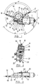
- All that has been mentioned up to now, together with other details of the invention, is pointed out in relation with the adjoinging pages of drawings, in which they are represented as follows:
- Figure 1 is an elevation of the assembly.
- Figure 2 is a view from the left of the previous figure, shown in cross section.
- Figure 3 is a view of figure 1 seen from the top.
- Figures 4 to 7 show different applications of the invention to different types of window winding mechanisms.
- In accordance with figure 1, we can observe the direct current micromotor (1), with the same feed voltage as that used in the vehicle that it is destined for, and with a power intake above the direct worm screw (2) which is cut or laminated on the rotor shaft and turns on two spherical bearings (3) made of suitable sintered material and self-lubricated, with axial supports (4) and (5) made of plastic material with a high resistance to wear and temperature, as they have to resist great alternative axial stresses while, at the same time, their turning friction has to be as low as possible so as to absorb the minimum possible energy, so that practically all the energy of the motor is available at the worm screw-spindle.
- On the motor support (6), in the shape of a circular bracket, an oil and damp retaining element is adapted (7), responsible for impeding, if necessary, these elements from passing into the electrical area of the brushes and the rotor collector, where they might be the cause of breakdowns, taking into account that the conditions of dampness and temperature inside the door panel might be very variable at certain moments. This support is preferably made by injection of reinforced fiber glass thermoplastic resin or light metal.
- The operation of the cable, in the case of window winding devices of this type, is made up of the toothed crown wheel (8), made of thermoplastic resin with a low friction coefficient, which gears on the worm screw-spindle (2) of the motor (1), and which forming part of the coplanary torque transmitter (9), draws over the drum that is integral to this system the two strands of cable (10 and 11) wound onto it and connected among themselves to the plate or unit for moving the pane of glass, as shown in figure 7.
- The cable system is supported by the two casing elements (14 and 15), made by injection of reinforced fiber glass thermoplastic resin and with a rotation shaft (16) inserted under pressure with its ends on the corresponding supports of the said housing.
- Of the two casings, it is (15) that houses the cable drum and has the outlets (17) directed in the most suitable position within the angles (α) or (β) included within the extreme positions (B-C) or (D-E), or else among the fixed positions (A) and that which is convenient within the angles mentioned previously.
- The compensation of the cable, according to whether it works in one direction or the other, is carried out by means of guides (12), made by injection of thermoplastic resin with a low friction coefficient, the cable conductors (26) and the helicoidal springs (13) shown in figure 1, which facilitates its sliding and compensation over the corresponding outlets (17) of the housing (15). Housing (14), which houses the crown wheel (8) and the torque transmitter (9), is connected to housing (15) by the shaft (16) and by the plastic deformation of the sectorial projections (18).
- Once that all the elements of this unit have been assembled, it is inserted into the bracket support (6) of the motor like a case, so that the crown wheel (8) will gear on the worm screw (2) and will be fastened to it by means of three rivets or bolts (10), thus shaping the compact motor-reducer that is extremely reduced in both size and weight, with the particular advantage that the motor can be exchanged by simply loosening the fixing elements (19) and then replacing them once that the change has been carried out.
- Housing (14) is a single part due to its geometry, so it can be used on one side or the other of the motor-reducer assembly, which means a considerable saving.
- This assembly is connected to the door of the vehicle by means of a simple anchoring plate (20), which clamps the motor in its rear part (figures 1 and 2) and is fixed by its front part through the only drill hole that the assembly has in the front support (6) of the motor, by means of a rivet or bolt (21) and its corresponding washer.
- The anchoring plate (20) is oversized at its support area on the door, so that the centre of gravity of the motor-reducer assembly falls within the box defined by the fixing elements, usually bolts (23). Like this, it is achieved that the dynamic stress that the system exercises on the door being closed, receives the push centrally and no tearing away of the sheet metal is produced in this area, a circumstance that is often produced in conventional systems which are fixed by one end, that of the head of the reducer, and leave the motor overhanging, even thouhg this is precisely the portion of greatest bulk and causes the previously mentioned tearing away, by moving the centre of gravity of the system outside the fixing area foreseen by the manufacturer of the vehicle.
- When dealing with the operation of window winding systems of the cable-rack type, for example the one shown in figure 5, the system is practically the same, with the only difference that the drum (9) is replaced by a pinion of suitable diameter and pitch in conformity with that of the cable-rack, and the casing (15) will have the appropriate housing and outlets for the said pinion and guide of the conductor pipes corresponding to the cable-rack.
- In case of operating window winding mechanisms with arm(s) with a toothed sector, as in figures 6 and 7, the frum (9) will be replaced by a pinion which will gear directly with the toothed sector, by which the housing (15) will be reduced to a simple cover, through which only the above-mentioned pinion will appear.
- Due to the fact that the drill holes for fixing (19) are arranged symmetrically around the axis M-M, a single motor-worm screw unit can be used for application to right or left window winding devices, which means a considerable advantage and saving in its use.
- Finally, and with regard to figure 4, we should like to point out that the assembly of the patent has been shown in its two possible positions (24) or (24a) in relation with a base unit (25) that uses cable.
- In figure 5, the patent (24) is shown with the element (26) that uses cable-rack, and in figures 6 and 7, the patent (24) or (24a) is fitted to devices that use arms (27) or an arm (28).
Claims (3)
- Motor and reducer support of the type which have a motor (1), with a cover for this motor, a support (6) for the semireducer, which is essentially characterized by:- one single part (6) which acts as a cover for the motor (1) and as a support for the semireducer, which has its axial shaft vertical (29) coinciding with that of the motor (1) and forming a single coaxial plane between both, in that the part (6) has a component in the shape of a circular segment with three drill holes (19) equidistant from each other, in that the centre of the circular segment coincides with the centre of the crown whell (8) and in that the power outlet from the crown wheel can be placed on one side or the other in relation to the vertical plane of the said circular segment that forms the cover.- the shaft (29), whose spiral or worm screw section (2) appears outside the cover through its lower section, holds a leaktight retainer (7) and a elastic joint with the motor casing, with the said cover also having one single drill hole in the section immediately below that of the worm screw and over the shaft perpendicular to that of the worm screw which passes through the turning centre of the crown wheel.- an assembly plate for anchorage to the vehicle door by means of a plate (20) on which the rear portion of the motor (1) is inserted and fixed in its forward position by a single bolt or rivet (21) to the motor front support, providing the necessary surface for the centre of gravity of the assembly to fall within the area assigned by the constructor for this purpose, thus preventing tearing of the sheet metal of the door panel, caused by slamming.- a casing (15), which form the cover and houses either the crown wheel (8) and the drum, or the crown wheel and the cover of the pinion outlet, is mounted on the element (6) in the form of a lid and is fixed to it by means of three elements (19) arranged symetrically with regard to a shaft that passes through the turning axis (16) of the crown wheel, allowing a single worm screw motor to be used, when the corresponding power connection is carried out on the right or on the left of the central plane of the motor.
- Motor and reducer support in accordance with claim 1, characterized in that for mechanisms which have to transmit small torques or which are small in size, the assembly can be constructed by the injection of fiber glass or mineral reinforced thermoplastic resins.
- Motor and reducer support in accordance with claim 1, characterized in that the input and output directions (17) of the cable or cable-rack can be arranged over a very wide angular range, which facilitates its adaptation to any type of door or the positioning of the mechanism inside it.
Applications Claiming Priority (3)
| Application Number | Priority Date | Filing Date | Title |
|---|---|---|---|
| ES294919U | 1986-06-19 | ||
| ES1986294919U ES294919Y (en) | 1986-06-19 | 1986-06-19 | REDUCED MOTOR SEMI-REDUCER |
| EP87500038A EP0278199B1 (en) | 1986-06-19 | 1987-06-17 | Improvements in vehicle window drive systems |
Related Parent Applications (1)
| Application Number | Title | Priority Date | Filing Date |
|---|---|---|---|
| EP87500038.2 Division | 1987-06-17 |
Publications (3)
| Publication Number | Publication Date |
|---|---|
| EP0501530A2 true EP0501530A2 (en) | 1992-09-02 |
| EP0501530A3 EP0501530A3 (en) | 1992-12-02 |
| EP0501530B1 EP0501530B1 (en) | 1997-05-28 |
Family
ID=8441693
Family Applications (1)
| Application Number | Title | Priority Date | Filing Date |
|---|---|---|---|
| EP92108208A Expired - Lifetime EP0501530B1 (en) | 1986-06-19 | 1987-06-17 | Motor and reducer support |
Country Status (3)
| Country | Link |
|---|---|
| EP (1) | EP0501530B1 (en) |
| DE (1) | DE3752069T2 (en) |
| ES (1) | ES294919Y (en) |
Cited By (2)
| Publication number | Priority date | Publication date | Assignee | Title |
|---|---|---|---|---|
| CN110345223A (en) * | 2019-08-05 | 2019-10-18 | 中国工程物理研究院机械制造工艺研究所 | A kind of motorized light mirror holder retarder and regulating member |
| EP3611324A1 (en) * | 2018-08-06 | 2020-02-19 | HI-LEX Corporation | Window glass raising / lowering device |
Family Cites Families (3)
| Publication number | Priority date | Publication date | Assignee | Title |
|---|---|---|---|---|
| DE2239256C2 (en) * | 1972-08-09 | 1985-01-17 | Brose Fahrzeugteile GmbH & Co KG, 8630 Coburg | Electric motor drive window regulators |
| US4167834A (en) * | 1978-02-15 | 1979-09-18 | Ferro Manufacturing Corporation | Power window mechanism |
| DE8128186U1 (en) * | 1981-09-25 | 1982-06-16 | Siemens AG, 1000 Berlin und 8000 München | TRANSMISSION MOTOR, ESPECIALLY ELECTRIC MOTOR WINDOW REGULATOR DRIVE FOR MOTOR VEHICLES |
-
1986
- 1986-06-19 ES ES1986294919U patent/ES294919Y/en not_active Expired
-
1987
- 1987-06-17 EP EP92108208A patent/EP0501530B1/en not_active Expired - Lifetime
- 1987-06-17 DE DE3752069T patent/DE3752069T2/en not_active Expired - Fee Related
Cited By (3)
| Publication number | Priority date | Publication date | Assignee | Title |
|---|---|---|---|---|
| EP3611324A1 (en) * | 2018-08-06 | 2020-02-19 | HI-LEX Corporation | Window glass raising / lowering device |
| CN110345223A (en) * | 2019-08-05 | 2019-10-18 | 中国工程物理研究院机械制造工艺研究所 | A kind of motorized light mirror holder retarder and regulating member |
| CN110345223B (en) * | 2019-08-05 | 2024-05-31 | 中国工程物理研究院机械制造工艺研究所 | Electric optical lens frame speed reducer and adjusting part |
Also Published As
| Publication number | Publication date |
|---|---|
| EP0501530A3 (en) | 1992-12-02 |
| DE3752069D1 (en) | 1997-07-03 |
| EP0501530B1 (en) | 1997-05-28 |
| ES294919Y (en) | 1987-11-01 |
| ES294919U (en) | 1987-03-16 |
| DE3752069T2 (en) | 1998-01-02 |
Similar Documents
| Publication | Publication Date | Title |
|---|---|---|
| AU2003233747B2 (en) | Device for displaceable divider elements, running gear and divider element | |
| BR9911314A (en) | Electric power assisted steering system. | |
| EP4006289B1 (en) | Electric strut | |
| EP2974896B1 (en) | Door opening and closing device | |
| CN1930757B (en) | In-line actuator apparatus and method | |
| ES2123396A1 (en) | Motor vehicle clutch assembly having a hydraulic actuator which hydraulic actuator has a transmission | |
| CN113090681B (en) | Clutch actuating mechanism and vehicle | |
| EP0211687A1 (en) | A gear mechanism | |
| EP0501530B1 (en) | Motor and reducer support | |
| EP0278199A2 (en) | Improvements in vehicle window drive systems | |
| CN201956799U (en) | Automobile skylight motor | |
| CN212562909U (en) | Automobile door driving mechanism | |
| CN212495156U (en) | Riveting drive mechanism and electronic riveting nut rifle | |
| CN220139358U (en) | Motor assembly | |
| JPS6040864A (en) | Device with flexible worm-nut for moving movable part | |
| CN1346320A (en) | Electrically supported steering boost with compact spur gear arrangement | |
| CN2563816Y (en) | Pipe shape motor with clutch device | |
| CN114941481B (en) | Integral heavy automatic hinge with spiral groove | |
| CN220707497U (en) | Indoor unit of air conditioner and air conditioner | |
| EP0713032A2 (en) | An electromechanical linear actuator for driving wing closing systems | |
| CN2355146Y (en) | Stepless angular regulator for electric fan | |
| CN116455129B (en) | Motor assembly | |
| CN215444934U (en) | Driver for automobile heating, ventilating and air conditioning | |
| CN214369172U (en) | Intelligent electric actuator based on cable | |
| US6681886B2 (en) | Flexibly coupled electric power assist steering system |
Legal Events
| Date | Code | Title | Description |
|---|---|---|---|
| PUAI | Public reference made under article 153(3) epc to a published international application that has entered the european phase |
Free format text: ORIGINAL CODE: 0009012 |
|
| 17P | Request for examination filed |
Effective date: 19920515 |
|
| AC | Divisional application: reference to earlier application |
Ref document number: 278199 Country of ref document: EP |
|
| AK | Designated contracting states |
Kind code of ref document: A2 Designated state(s): DE FR GB IT |
|
| PUAL | Search report despatched |
Free format text: ORIGINAL CODE: 0009013 |
|
| AK | Designated contracting states |
Kind code of ref document: A3 Designated state(s): DE FR GB IT |
|
| 17Q | First examination report despatched |
Effective date: 19950407 |
|
| GRAG | Despatch of communication of intention to grant |
Free format text: ORIGINAL CODE: EPIDOS AGRA |
|
| GRAH | Despatch of communication of intention to grant a patent |
Free format text: ORIGINAL CODE: EPIDOS IGRA |
|
| GRAH | Despatch of communication of intention to grant a patent |
Free format text: ORIGINAL CODE: EPIDOS IGRA |
|
| GRAA | (expected) grant |
Free format text: ORIGINAL CODE: 0009210 |
|
| AC | Divisional application: reference to earlier application |
Ref document number: 278199 Country of ref document: EP |
|
| AK | Designated contracting states |
Kind code of ref document: B1 Designated state(s): DE FR GB IT |
|
| REF | Corresponds to: |
Ref document number: 3752069 Country of ref document: DE Date of ref document: 19970703 |
|
| ET | Fr: translation filed | ||
| PLBE | No opposition filed within time limit |
Free format text: ORIGINAL CODE: 0009261 |
|
| STAA | Information on the status of an ep patent application or granted ep patent |
Free format text: STATUS: NO OPPOSITION FILED WITHIN TIME LIMIT |
|
| 26N | No opposition filed | ||
| PGFP | Annual fee paid to national office [announced via postgrant information from national office to epo] |
Ref country code: FR Payment date: 19990602 Year of fee payment: 13 |
|
| PGFP | Annual fee paid to national office [announced via postgrant information from national office to epo] |
Ref country code: GB Payment date: 19990607 Year of fee payment: 13 |
|
| PGFP | Annual fee paid to national office [announced via postgrant information from national office to epo] |
Ref country code: DE Payment date: 19990823 Year of fee payment: 13 |
|
| PG25 | Lapsed in a contracting state [announced via postgrant information from national office to epo] |
Ref country code: GB Free format text: LAPSE BECAUSE OF NON-PAYMENT OF DUE FEES Effective date: 20000617 |
|
| GBPC | Gb: european patent ceased through non-payment of renewal fee |
Effective date: 20000617 |
|
| PG25 | Lapsed in a contracting state [announced via postgrant information from national office to epo] |
Ref country code: FR Free format text: LAPSE BECAUSE OF NON-PAYMENT OF DUE FEES Effective date: 20010228 |
|
| REG | Reference to a national code |
Ref country code: FR Ref legal event code: ST |
|
| PG25 | Lapsed in a contracting state [announced via postgrant information from national office to epo] |
Ref country code: DE Free format text: LAPSE BECAUSE OF NON-PAYMENT OF DUE FEES Effective date: 20010403 |
|
| PG25 | Lapsed in a contracting state [announced via postgrant information from national office to epo] |
Ref country code: IT Free format text: LAPSE BECAUSE OF NON-PAYMENT OF DUE FEES;WARNING: LAPSES OF ITALIAN PATENTS WITH EFFECTIVE DATE BEFORE 2007 MAY HAVE OCCURRED AT ANY TIME BEFORE 2007. THE CORRECT EFFECTIVE DATE MAY BE DIFFERENT FROM THE ONE RECORDED. Effective date: 20050617 |