EP0500714B2 - Arrangement for semi-active or active control of damping members in a vehicle suspension system - Google Patents
Arrangement for semi-active or active control of damping members in a vehicle suspension system Download PDFInfo
- Publication number
- EP0500714B2 EP0500714B2 EP90917208A EP90917208A EP0500714B2 EP 0500714 B2 EP0500714 B2 EP 0500714B2 EP 90917208 A EP90917208 A EP 90917208A EP 90917208 A EP90917208 A EP 90917208A EP 0500714 B2 EP0500714 B2 EP 0500714B2
- Authority
- EP
- European Patent Office
- Prior art keywords
- mass
- magazine
- bracket
- sensor
- wire
- Prior art date
- Legal status (The legal status is an assumption and is not a legal conclusion. Google has not performed a legal analysis and makes no representation as to the accuracy of the status listed.)
- Expired - Lifetime
Links
Images

Classifications
-
- B—PERFORMING OPERATIONS; TRANSPORTING
- B60—VEHICLES IN GENERAL
- B60G—VEHICLE SUSPENSION ARRANGEMENTS
- B60G17/00—Resilient suspensions having means for adjusting the spring or vibration-damper characteristics, for regulating the distance between a supporting surface and a sprung part of vehicle or for locking suspension during use to meet varying vehicular or surface conditions, e.g. due to speed or load
- B60G17/015—Resilient suspensions having means for adjusting the spring or vibration-damper characteristics, for regulating the distance between a supporting surface and a sprung part of vehicle or for locking suspension during use to meet varying vehicular or surface conditions, e.g. due to speed or load the regulating means comprising electric or electronic elements
- B60G17/019—Resilient suspensions having means for adjusting the spring or vibration-damper characteristics, for regulating the distance between a supporting surface and a sprung part of vehicle or for locking suspension during use to meet varying vehicular or surface conditions, e.g. due to speed or load the regulating means comprising electric or electronic elements characterised by the type of sensor or the arrangement thereof
- B60G17/01933—Velocity, e.g. relative velocity-displacement sensors
-
- B—PERFORMING OPERATIONS; TRANSPORTING
- B60—VEHICLES IN GENERAL
- B60G—VEHICLE SUSPENSION ARRANGEMENTS
- B60G2400/00—Indexing codes relating to detected, measured or calculated conditions or factors
- B60G2400/25—Stroke; Height; Displacement
-
- B—PERFORMING OPERATIONS; TRANSPORTING
- B60—VEHICLES IN GENERAL
- B60G—VEHICLE SUSPENSION ARRANGEMENTS
- B60G2401/00—Indexing codes relating to the type of sensors based on the principle of their operation
- B60G2401/14—Photo or light sensitive means, e.g. Infrared
Definitions
- the invention relates to an arrangement for controlling the damping members in a vehicle suspension system as a function of the movement between the undamped and damped mass in accordance with the preamble of the Patent Claim.
- Such an arrangement is known from document EP-A-174 914.
- the damping members arranged in the suspension system are controlled semi-actively between different levels of damping capacity in order to obtain the least possible throughput and transmission of the movement of the undamped mass to the damped mass.
- the damping members can be controlled actively by pressurising or evacuating the chamber of the shock absorbers as a function of detected parameters.
- German Patent Application DE-3,518,503 a solution is shown in which accelerometers are used for controlling the shock absorbers.
- the accelerometers are in this case arranged both on the undamped mass, the wheel, and on the damped mass, the bodywork.
- European Patent application EP-A-174 914 shows an arrangement where relative linear displacements between two members are detected.
- One of the members rotably supports a rotor.
- a flexible member is connected to the rotor and to the other member in such a way as to cause rotation of the rotor when the members move away from each other.
- a return spring tends to rotate the roter in the opposite direction when the members move towards each other.
- the angular position of the rotor relative to the member that it is supported by and hence the two members relative position are detected by electrical sensor means.
- An object of the present invention is to obtain, in an arrangement for controlling shock absorbers either actively or semi-actively, a simple and inexpensive sensor for detecting the movement between the undamped and damped mass.
- Another object is to obtain a sensor which does not need to lie parallel over the spring distance and in addition does not require too great a space in connection with the damped mass or alternatively undamped mass.
- Another object is to obtain a sensor which can be mounted on or dismounted from the respective mass in a simple manner, either as a subsequent fitting on the finished vehicle or in the event of a shock absorber replacement.
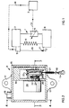
- FIG. 1 shows an arrangement according to the invention for controlling damping members in a vehide suspension system.
- the suspension system 1 consists of an adjustable shock absorber 5 and a parallel-coupled spring member 6.
- the shock absorber 5 and the spring member 6 are arranged between a mass 7 wnich will be insulated with respect to disturbance impulses from the mass 8.
- the mass 7 is referred to in a conventional manner as the damped mass and the mass 8 as the undamped mass.
- the function of the shock absorber 5 is regulated by means of a control unit 2 via control signals through line 13.
- a sensor arrangement 9-12 is coupled between the masses.
- the sensor 9 transmits signals to the control unit 2 via a signal line 14 as a function of the speed, position and direction of the movement.
- the spring member 6 in Figure 1 is shown diagrammatically as a coil spring, but in fact it can consist of other types of spring members, such as pneumatic bellows springs, leaf springs or the like.
- the adjustable shock absorber 5 can either be of a semi-active type. whose intrinsic damping capacity is adjustable, or of an active type, whose active damping capacity is regulated by means of controlled pressurising or evacuating by external flow control of the chambers of the shock absorber.
- a sensor 9 is used which is arranged on one of the masses 7 and which is coupled via a wire 10 to the second mass 8.
- the wire 10 is anchored to the second mass 8 by means of a catch 11 in an eye 12 arranged in this mass 8.
- the sensor 9 is shown in greater detail in Figures 2-4 and consists of an optical pulse transmitter 24 which converts a rotational movement to an electric pulse train.
- the pulse transmitter 24 is coupled to a shaft 21 on which there is arranged a wire pulley 20 which is rotationally fixed to the shaft and which is spring-loaded towards a bracket 16 arranged in the sensor housing 15.
- the shaft 21 is held in the bracket 16 via ball bearings 22 and is connected, fixed in terms of rotation, to a code disc (not shown) arranged in the optical pulse transmitter.
- the optical pulse transmitter 24 is screwed securely on the bracket by means of screws (not shown) and is separated from the wire pulley by one of the ball bearings.
- the pulse transmitter 24 can advantageously consist of an optical pulse transmitter of the Hewlett Packard HEADS-5500 type. This type of position indicator has hitherto been used to a great extent in, among other things, writing equipement.
- the pulse transmitter comprises a rotatable code disc with narrow gaps, which codes disc passes between a light-emitting diode and a set of photodiodes.
- the lightfrom the light-emitting diode is focused towards the gaps on the code disc by means of a lens and, with photodiodes on the other side of the code disc, a pulse is obtained each time a gap rotates past the photodiodes.
- a pulse is obtained each time a gap rotates past the photodiodes.
- the sensor housing 15 is designed with a pair of securing lugs 17 which permit anchoring on either mass 7, 8 by means of conventional securing elements (not shown).
- the pulse transmitter 24 is coupled to the control unit 2 via an electric signal line.
- the sensor housing 15 is therefore provided with a cable passage 18.
- Wound around the wire pulley 20 is a wire 10 whose end is anchored in the pulley 20.
- the shaft 21 of the wire pulley 20 is held in ball bearings 22 in the bracket 16 and the fact that the wire pulley 20 is simultaneously acted upon by the coil spring 23, whose one spring end 26 is anchored in the bracket 16 and whose other spring end 25 is anchored in the pulley 20, the wire 10 rolled around the pulley 20 can be drawn out from the pulley 20 under the counteraction of the spring 23. In this way the wire 10 is at all times tensioned both during its reeling-out and reeling-in around the wire pulley 20.
- the sensor housing 15 can in this way be assembled in a simple manner securely on either of the masses 7, 8, after which the wire 10 is drawn out and is hooked securely by means of the catch 11 in the eye 12 arranged on the second mass.
- the sensor can be adapted in a simple manner to different types of spring systems with different distances between the anchoring points for the sensor housing 15 and the eye 12 of the wire 10.
- the same sensor can be used for both a front wheel suspension and a rear wheel suspension, despite the fact that there may be differences in the attachment points and the spring distance.
- the arrangement is advantageously used in semi-actively or actively spring-mounted lorry cabins where the cabin obtains full suspension relative to the lorry frame via a spring system which is arranged in each one of the four corners of the cabin.
- the sensor 9 can be placed in a protected position in the cabin or on the floor of the cabin, where the wire, optionally via deflection rollers, is drawn down to an anchoring point secured on the lorry frame.
- the above description of an exemplary embodiment of the arrangement according to the invention must not be regarded as limiting the inventive concept as set out in the patent claims.
- the invention can be modified within the scope of the patent daims in a number of embodiments.
- the wire mentioned in the patent daims can of course consist of a conventional multi-filament wire or a single-filament wire of metal material, alloys, polymer material or other materials of comparable properties. Chains also can be compared with a wire from the point of view of functioning in the present invention, and in such cases the magazine advantageously consists of a chain drive.
- the spring member 23 specified in the claims can also consist of a pneumatic or hydraulic spring arrangement which can operate functionally in a similar manner to a coil spring.
Landscapes
- Engineering & Computer Science (AREA)
- Mechanical Engineering (AREA)
- Vehicle Body Suspensions (AREA)
Abstract
Description
Claims (1)
- Arrangement for controlling damping members incorporated in a suspension system between an undamped and a damped mass (7, 8), consisting of at least one set of an adjustable damping member (5) and a parallel-coupled spring member (6), which damping member (5) is regulated by means of a signal representing a movement, detected by a sensor (9), between the undamped (8) and the damped (7) mass, the sensor (9) being arranged securely on one (7) of the two masses (7, 8), having a chain or a wire which is wound on a rotatable magazine (20) with. pretensioning of a spring member (23) acting counter to the rotation of the magazine (20), and having the chain or wire at its one end to be drawn from the magazine (20) designed to be secured by means of coupling members (11,12) on the second mass (8), and the rotatable magazine (20) being designed to act on a pulse transmitter (24) in proportion to the rotation of the magazine (20), which pulse transmitter (24) generates an electrical signal for controlling the damping member (5) characterised in that the undamped mass (7) is a lorry frame and the damped mass (8) is a lorry cabin, that the sensor has a housing (15) arranged inside the lorry cabin (8) and the coupling members are secured to the lorry frame, which sensor is electrically connected to a control unit (2), through which the damping member is controlled, in which housing a bracket (16) is securely arranged, which bracket holds by means of bearing members a shaft, on which shaft the magazine (20) and one end of the spring member (23) are fixed, the other end of the spring member being locked to the bracket, the pulse transmitter (24) being securely arranged on the bracket for detecting the turning of the shaft and the bracket having a bearing member separating the pulse transmitter from the magazine, which magazine, pulse transmitter, spring member, bracket and shaft all are incorporated in the housing.
Applications Claiming Priority (3)
| Application Number | Priority Date | Filing Date | Title |
|---|---|---|---|
| SE8903787 | 1989-11-13 | ||
| SE8903787A SE464929B (en) | 1989-11-13 | 1989-11-13 | ARRANGEMENTS FOR SEMIACTIVE OR ACTIVE CONTROL OF DAEMPORGAN IN A VEHICLE SPRING |
| PCT/SE1990/000727 WO1991007607A1 (en) | 1989-11-13 | 1990-11-09 | Arrangement for semi-active or active control of damping members in a vehicle suspension system |
Publications (3)
| Publication Number | Publication Date |
|---|---|
| EP0500714A1 EP0500714A1 (en) | 1992-09-02 |
| EP0500714B1 EP0500714B1 (en) | 1994-05-11 |
| EP0500714B2 true EP0500714B2 (en) | 1998-01-14 |
Family
ID=20377446
Family Applications (1)
| Application Number | Title | Priority Date | Filing Date |
|---|---|---|---|
| EP90917208A Expired - Lifetime EP0500714B2 (en) | 1989-11-13 | 1990-11-09 | Arrangement for semi-active or active control of damping members in a vehicle suspension system |
Country Status (4)
| Country | Link |
|---|---|
| EP (1) | EP0500714B2 (en) |
| DE (1) | DE69008863T3 (en) |
| SE (1) | SE464929B (en) |
| WO (1) | WO1991007607A1 (en) |
Families Citing this family (1)
| Publication number | Priority date | Publication date | Assignee | Title |
|---|---|---|---|---|
| DE102017205000A1 (en) * | 2017-03-24 | 2018-09-27 | Zf Friedrichshafen Ag | Measuring device for a vibration damper |
Family Cites Families (3)
| Publication number | Priority date | Publication date | Assignee | Title |
|---|---|---|---|---|
| DE3518503C1 (en) * | 1985-05-23 | 1986-10-23 | Daimler-Benz Ag, 7000 Stuttgart | Device for computer-aided, road-dependent control of dampers of a vehicle suspension |
| US4821849A (en) * | 1986-09-29 | 1989-04-18 | Lord Corporation | Control method and means for vibration attenuating damper |
| DE3738284A1 (en) * | 1986-12-09 | 1988-06-30 | Bosch Gmbh Robert | DEVICE FOR ACTIVE CHASSIS CONTROL IN MOTOR VEHICLES |
-
1989
- 1989-11-13 SE SE8903787A patent/SE464929B/en not_active IP Right Cessation
-
1990
- 1990-11-09 EP EP90917208A patent/EP0500714B2/en not_active Expired - Lifetime
- 1990-11-09 DE DE69008863T patent/DE69008863T3/en not_active Expired - Fee Related
- 1990-11-09 WO PCT/SE1990/000727 patent/WO1991007607A1/en not_active Ceased
Also Published As
| Publication number | Publication date |
|---|---|
| DE69008863T3 (en) | 1998-08-06 |
| DE69008863D1 (en) | 1994-06-16 |
| WO1991007607A1 (en) | 1991-05-30 |
| EP0500714B1 (en) | 1994-05-11 |
| SE8903787L (en) | 1991-05-14 |
| SE8903787D0 (en) | 1989-11-13 |
| EP0500714A1 (en) | 1992-09-02 |
| SE464929B (en) | 1991-07-01 |
| DE69008863T2 (en) | 1994-12-01 |
Similar Documents
| Publication | Publication Date | Title |
|---|---|---|
| US4796911A (en) | Automotive suspension system with roll-stabilizer having road condition-dependent torsion modulus, and control of torsional modules | |
| DE69912473T2 (en) | IMPACT SENSOR BY MEANS OF ELECTROMAGNETIC RADIATION ELEMENTS INSTALLED IN A IMPACT ZONE OF A MOTOR VEHICLE | |
| EP1117546B1 (en) | Vehicle roll control | |
| WO1987005570A1 (en) | Device for automatic release of passenger protection devices in the event of an accident | |
| US4886291A (en) | Fail-safe system for automotive suspension control system | |
| EP1117547B1 (en) | Vehicle roll control | |
| US4657289A (en) | Orbital electrical power and signal generator mountable on a rotatable body | |
| AU2007306559A1 (en) | System for indicating the state of loading of a vehicle | |
| CA2020713A1 (en) | Semi-Active Suspension Control System with Reduced Switching Frequency in Hard and Soft Suspension Characteristics | |
| SE466796B (en) | SPRING SYSTEM WITH CONDITIONING RESONANCE DIMENSION AND PROCEDURE FOR REGULATING THE SPRING SYSTEM | |
| US6142655A (en) | Device for regulating light width of headlights for vehicles, and vehicle provided therewith | |
| EP0611344B1 (en) | Vehicle driving wheel suspension system | |
| CA2029709A1 (en) | Suspension control apparatus | |
| CH707495A2 (en) | Mounting system for opto-electronic instruments. | |
| CA2227435A1 (en) | Tilt control apparatus for vehicles | |
| US5161816A (en) | Suspension control apparatus | |
| EP0500714B1 (en) | Arrangement for semi-active or active control of damping members in a vehicle suspension system | |
| EP1060376A1 (en) | Method and device for monitoring the area of technical rolling bodies | |
| DE2414171B2 (en) | Measuring device for measuring the damping effectiveness of shock absorbers | |
| CA1286154C (en) | Wheelset steering apparatus and method for the truck of railway vehicles | |
| GB2339880A (en) | Reducing vibrations | |
| DE10258265A1 (en) | Monitoring of a motor vehicle shock absorber system to detect abnormal behavior by comparison of the recorded attenuation behavior or frequency of a shock absorber with theoretical values to indicate a problem or otherwise | |
| DE10333284B4 (en) | Monitoring the axial load acting on the hub of a motor vehicle wheel | |
| US4700812A (en) | Vehicular suspension system | |
| US6234492B1 (en) | Method and system for providing variable load control and isolation in a vehicle suspension |
Legal Events
| Date | Code | Title | Description |
|---|---|---|---|
| PUAI | Public reference made under article 153(3) epc to a published international application that has entered the european phase |
Free format text: ORIGINAL CODE: 0009012 |
|
| 17P | Request for examination filed |
Effective date: 19920424 |
|
| AK | Designated contracting states |
Kind code of ref document: A1 Designated state(s): DE GB SE |
|
| 17Q | First examination report despatched |
Effective date: 19931014 |
|
| GRAA | (expected) grant |
Free format text: ORIGINAL CODE: 0009210 |
|
| AK | Designated contracting states |
Kind code of ref document: B1 Designated state(s): DE GB SE |
|
| PG25 | Lapsed in a contracting state [announced via postgrant information from national office to epo] |
Ref country code: SE Free format text: THE PATENT HAS BEEN ANNULLED BY A DECISION OF A NATIONAL AUTHORITY Effective date: 19940511 |
|
| REF | Corresponds to: |
Ref document number: 69008863 Country of ref document: DE Date of ref document: 19940616 |
|
| PLBI | Opposition filed |
Free format text: ORIGINAL CODE: 0009260 |
|
| 26 | Opposition filed |
Opponent name: ASM AUTOMATION SENSRIK MESSTECHNIK GMBH Effective date: 19941026 |
|
| PLAB | Opposition data, opponent's data or that of the opponent's representative modified |
Free format text: ORIGINAL CODE: 0009299OPPO |
|
| PGFP | Annual fee paid to national office [announced via postgrant information from national office to epo] |
Ref country code: GB Payment date: 19951031 Year of fee payment: 6 |
|
| R26 | Opposition filed (corrected) |
Opponent name: ASM AUTOMATION SENSRIK MESSTECHNIK GMBH Effective date: 19941026 |
|
| REG | Reference to a national code |
Ref country code: GB Ref legal event code: 732E |
|
| PG25 | Lapsed in a contracting state [announced via postgrant information from national office to epo] |
Ref country code: GB Effective date: 19961109 |
|
| GBPC | Gb: european patent ceased through non-payment of renewal fee |
Effective date: 19961109 |
|
| PLAW | Interlocutory decision in opposition |
Free format text: ORIGINAL CODE: EPIDOS IDOP |
|
| PUAH | Patent maintained in amended form |
Free format text: ORIGINAL CODE: 0009272 |
|
| STAA | Information on the status of an ep patent application or granted ep patent |
Free format text: STATUS: PATENT MAINTAINED AS AMENDED |
|
| 27A | Patent maintained in amended form |
Effective date: 19980114 |
|
| AK | Designated contracting states |
Kind code of ref document: B2 Designated state(s): DE GB SE |
|
| PGFP | Annual fee paid to national office [announced via postgrant information from national office to epo] |
Ref country code: DE Payment date: 19981116 Year of fee payment: 9 |
|
| PG25 | Lapsed in a contracting state [announced via postgrant information from national office to epo] |
Ref country code: DE Free format text: LAPSE BECAUSE OF NON-PAYMENT OF DUE FEES Effective date: 20000901 |
|
| PLAB | Opposition data, opponent's data or that of the opponent's representative modified |
Free format text: ORIGINAL CODE: 0009299OPPO |