EP0500231B1 - Fuel pumping apparatus - Google Patents
Fuel pumping apparatus Download PDFInfo
- Publication number
- EP0500231B1 EP0500231B1 EP92300967A EP92300967A EP0500231B1 EP 0500231 B1 EP0500231 B1 EP 0500231B1 EP 92300967 A EP92300967 A EP 92300967A EP 92300967 A EP92300967 A EP 92300967A EP 0500231 B1 EP0500231 B1 EP 0500231B1
- Authority
- EP
- European Patent Office
- Prior art keywords
- shuttle
- valve
- piston
- cylinder
- fuel
- Prior art date
- Legal status (The legal status is an assumption and is not a legal conclusion. Google has not performed a legal analysis and makes no representation as to the accuracy of the status listed.)
- Expired - Lifetime
Links
Images


Classifications
-
- F—MECHANICAL ENGINEERING; LIGHTING; HEATING; WEAPONS; BLASTING
- F02—COMBUSTION ENGINES; HOT-GAS OR COMBUSTION-PRODUCT ENGINE PLANTS
- F02M—SUPPLYING COMBUSTION ENGINES IN GENERAL WITH COMBUSTIBLE MIXTURES OR CONSTITUENTS THEREOF
- F02M41/00—Fuel-injection apparatus with two or more injectors fed from a common pressure-source sequentially by means of a distributor
- F02M41/08—Fuel-injection apparatus with two or more injectors fed from a common pressure-source sequentially by means of a distributor the distributor and pumping elements being combined
- F02M41/14—Fuel-injection apparatus with two or more injectors fed from a common pressure-source sequentially by means of a distributor the distributor and pumping elements being combined rotary distributor supporting pump pistons
- F02M41/1405—Fuel-injection apparatus with two or more injectors fed from a common pressure-source sequentially by means of a distributor the distributor and pumping elements being combined rotary distributor supporting pump pistons pistons being disposed radially with respect to rotation axis
- F02M41/1411—Fuel-injection apparatus with two or more injectors fed from a common pressure-source sequentially by means of a distributor the distributor and pumping elements being combined rotary distributor supporting pump pistons pistons being disposed radially with respect to rotation axis characterised by means for varying fuel delivery or injection timing
Definitions
- This invention relates to a fuel pumping apparatus for supplying fuel to an internal combustion engine and of the kind comprising a rotary distributor member housed in a body, the distributor member being driven in synchronism with the associated engine, a bore formed in the distributor member and a pumping plunger therein, a cam mounted in the body and having a plurality of cam lobes adapted to impart inward movements to the pumping plunger as the distributor member rotates, a passage connected with the bore and arranged to communicate in turn as the distributor member rotates with a plurality of outlet ports, the outlet ports being formed in the body and being connected in use to the injection nozzles respectively of the associated engine, means including a low pressure fuel pump for feeding fuel to the bore to effect full outward movement of the pumping plunger in the intervals between the inward movements thereof, a fluid pressure operable normally closed valve which when open, allows fuel to escape from the bore during the inward movement of the plunger therein, to terminate delivery of fuel through an outlet, a further plunger mounted in a further bore
- the shuttle is returned to the one end of the cylinder as the further plunger is allowed to move outwardly.
- the return motion of the shuttle is conveniently effected by means of a spring.
- some form of anti-friction bearing must be provided between the spring and the shuttle or between the spring and a spring abutment in order that angular movement of the shuttle by the actuating mechanism shall not be impaired.
- the spring abutment must be made to move angularly with the shuttle an arrangement which involves some form of coupling which can itself cause friction.
- a further consideration is the stress to which the spring is subjected when the apparatus is in use.
- the pressure of fuel which is supplied to the one end of the cylinder does not approach the pressure of fuel developed by the pumping plunger it nevertheless will be appreciably higher than the fuel pressure which is developed by the low pressure fuel pump.
- the spring must be able to generate sufficient force so that the shuttle is held at said one end of the cylinder when said passage means is connected to the outlet of the low pressure pump in order to make up any leakage of fuel which has taken place during the preceding cycle of operation of the further plunger.
- the travel of the shuttle is considerable and the frequency of operation is high. The above considerations require a demanding spring specification.
- the object of the invention is to provide an apparatus of the kind specified in a simple and convenient form.
- an apparatus of the kind specified comprises a shuttle return piston slidable within a further cylinder, the shuttle return piston engaging the end of the shuttle remote from said one end of the shuttle cylinder, the diameter of said shuttle return piston being slightly greater than that of the shuttle, an accumulator chamber connected to the end of the further cylinder remote from the shuttle, a restriction for restricting the rate at which fluid can pass between the further cylinder and the accumulator chamber and said accumulator chamber being in part defined by a spring loaded piston having an area which is greater than the area of the shuttle return piston.
- the apparatus comprises a body 10 in which is mounted a fixed sleeve 11 defining a bore to receive a rotary cylindrical distributor member 12.
- the distributor member has an enlarged diameter portion projecting from the bore and in use is driven in timed relationship with an associated engine.
- a transverse bore 13 In which is mounted a pair of pumping plungers 14 the outer ends of which engage cam followers 15 each cam follower comprising a shoe 16 and a roller 17.
- the rollers engage the internal peripheral surface of an annular cam ring 18 which is mounted within the body 10.
- the angular position of the cam ring is adjustable by means of a fluid pressure operable spring biased piston 19, in known manner.
- the bore 13 is in communication with a longitudinal passage 20 which at one point communicates with a radially disposed delivery passage 21 positioned to register in turn with a plurality of outlet ports 22 formed in the sleeve and extending to outlets 23 respectively which are connected in use to the injection nozzles of the associated engine.
- the passage 20 is in communication with a plurality of radially disposed inlet passages 24 which are positioned to register in turn with inlet ports 25 formed in the sleeve 11 and communicating by way of an on/off valve 26, with the outlet of a low pressure fuel supply pump 27 having a fuel inlet 28.
- a low pressure fuel supply pump 27 having a fuel inlet 28.
- the inlet and outlet of the supply pump 27 are interconnected by way of a relief valve and the rotary part of the pump is coupled to the distributor member.
- the output pressure of the low pressure pump 27 varies in accordance with the speed at which the distributor member is driven and the aforesaid piston 19 is subjected to the outlet pressure of the low pressure pump so that the angular setting of the cam ring depends upon the speed of the associated engine.
- the passage 21 is arranged to register with an outlet port 22 during the whole time the plungers 14 are moved inwardly so that fuel displaced from the bore 13 can flow to the associated engine.
- the passage 21 moves out of register with an outlet port 22 and an inlet passage 24 moves into register with an inlet port 25.
- Fuel is therefore supplied to the bore 13 from the outlet of the low pressure pump and the plungers 14 are moved outwardly to their maximum extent so that the rollers engage the base circle of the cam ring. As described there is no method of controlling the quantity of fuel supplied through an outlet 23.
- a further transverse bore 29 in the enlarged portion of the distributor member and located in the bore is a pair of further or auxiliary plungers 30 the outer ends of which engage the shoes 16 so that the auxiliary plungers are moved inwardly at the same time as the pumping plungers.
- the bore 29 is in constant communication with a circumferential groove 31 formed in the periphery of the distributor member and this groove is in constant communication with one end of a shuttle cylinder 32 which for convenience is defined by the bore of a sleeve 33 which is angularly adjustable within the body part 10 but is restrained from axial movement.
- Slidable within the shuttle cylinder 32 is a shuttle 34 which is biased as will be described, towards the one end of the cylinder.
- the port 36 is in constant communication with a circumferential groove 38 formed on the distributor member whilst the port 37 is in constant communication with a port 39 which is formed in the sleeve and which opens onto the periphery of the distributor member at a position to register with the inlet passages 24.
- the registration of the port 39 with an inlet passage 24 is arranged to occur during the time the pumping plungers 14 are moved inwardly.
- the shuttle 34 is provided with a groove 40 which is in constant communication with the port 36 and extending from the groove 40 is an inclined groove 41 which as will be explained, is positioned to register with the port 37 after a predetermined movement of the shuttle.
- the shuttle is angularly adjustable and for this purpose is provided with an arm 42 which is coupled to an actuating mechanism in the form of a governor 42A.
- a normally closed valve generally indicated at 43 and including a piston 44 which is housed within a cylinder 45 defined in an extension of the distributor member 12.
- the piston 44 is integral with a valve member 46 which co-operates with a seating defined in the end wall of the cylinder 45, the seating being located at one end of a passage 47 which communicates with the bore 13.
- the piston 44 is biased by a spring 48 so that the valve member 46 engages with the seating 48 and the spring is sufficiently strong to ensure that the valve member 46 is held in sealing engagement with the seating.
- the port 37 is brought into register with the groove 41 and fuel at the high pressure developed by the plungers 14 is supplied to the inner end of the cylinder 45 and this fuel acts upon the piston 44 to urge the piston against the action of the spring 48.
- the valve member is lifted from its seating and the remaining fuel which is displaced by the plungers 14 can flow into the cylinder 45 through the passage 47 thereby displacing the piston 44 against the action of the spring 48.
- the shuttle By moving the shuttle angularly the quantity of fuel which can be supplied to the associated engine can be varied.
- the arm 42 is connected to the governor 42A which will be either of the so-called all-speed type or the so-called two-speed type.
- the sleeve 33 can also be moved angularly and two ways of achieving this are illustrated.
- a fluid pressure operable piston 59 is provided, the piston being spring biased against the action of the outlet pressure of the low pressure pump.
- Another way of moving the sleeve is by means of an air pressure responsive diaphragm 60 which is responsive to the pressure of air delivered to the associated engine, the piston 59 and the diaphragm 60 can if desired, both be provided to control the position of the sleeve.
- the plungers When the plungers complete their inward movement and the rollers 17 move over the crests of the cam lobes, the plungers can move outwardly and fuel is returned from the one end of the cylinder 45 to the bore 13 by movement of the piston 44 by the spring 48. However, since fuel may have been supplied to the associated engine, fuel is supplied through one of the inlet passages 24 to the bore 13 to ensure that the plungers move outwardly their maximum extent. The shuttle 34 will also be urged towards the inner end of the cylinder 32 displacing fuel back to the bore 29.
- auxiliary filling ports 61 connected to the outlet of the fuel supply pump and communicating at the appropriate time, with a passage 62 in the distributor member and which is in communication with the bore 29.
- the plungers 30 are moved outwardly to their maximum extent.
- FIG. 2 the outer end of the shuttle 34 is engaged by a shuttle return piston 50 which is slidable in a further cylinder 51. Also provided is an accumulator chamber 52 which is in communication with the cylinder 51 by way of a passage 53 incorporating a restrictor 54. The accumulator chamber is in communication with the outlet of the low pressure pump 27 by way of a one way valve 55 and the accumulator chamber is in part defined by an accumulator piston 56 which is spring biased by means of a spring 57 towards a stop 58. The area of the accumulator piston 56 is greater than that of the shuttle return piston 50 which in turn is larger than that of the shuttle 34.
- the spring 57 is of sufficient strength so as to be able to hold the accumulator piston 56 against the stop 58 against the force developed on the piston by the output pressure of the low pressure pump 27.
- the area of contact between the shuttle 34 and the return piston 50 is minimised by making the presented surface of one of the components, in this case the shuttle, of convex form.
- the non-return valve 55 opens to allow fuel flow into the accumulator chamber 52 to make up for any fuel which has leaked along the working clearances between the pistons 50 and 56 and the respective cylinders. Moreover, even when the passage 62 is brought into register with a port 61 and fuel at the outlet pressure of the low pressure pump is applied to the underside of the shuttle, there will still be a net force acting to urge the shuttle 34 and the shuttle return piston 50 downwardly in view of the larger diameter of the return piston 50, and since the space between the shuttle 34 and the return piston 50 is at a low pressure.
- the purpose of the restrictor 54 is to damp the movement of the shuttle 34 and the shuttle return piston 50, in particular to ensure that the shuttle 34 does not separate from the fuel column between the shuttle and the auxiliary plungers 30 and to ensure that the auxiliary plungers 30 remain under the control of the cam lobes.
- the body 10 is located within a housing or casing 9 which defines a chamber 8 which is closed by a cover 7.
- the chamber contains fuel at low pressure.
- the shuttle 34 and sleeve 33 extend into the chamber and within the chamber there is formed a locating surface 61A.
- a support body 62A Accommodated within the chamber is a support body 62A which is secured by screws to the portion of the casing which defines the locating surface 61A and a stop bracket 63 of double "L" shaped form has one of its limbs interposed between the locating surface and the support body.
- the other limb of the stop bracket is apertured to allow the shuttle 34 to pass therethrough and the stop bracket is accurately located by means of a dowel pin 64.
- This limb of the stop bracket on one face serves to locate the sleeve 33 and its other face serves as a stop face which is engageable by the arm 42 to limit the movement of the shuttle 34 into the sleeve 33.
- the support body 62A carries a flanged shaft 65 which is a press fit in the support body and angularly movable about the shaft and located between the flange thereof and the support body is a lever 66 in which is mounted a depending pin 67.
- a roller 68 mounted about the pin is a roller 68 having a groove in which is located a governor link which forms what can be regarded as the output member of the governor mechanism 42A.
- the pin 67 is also engaged with the arm 41 in such a manner that the arm can move axially relative to the pin as the shuttle 34 moves axially but movement of the pin with the lever 66 will impart angular movement to the shuttle.
- the flanged shaft 65 defines the cylinder 51 for the shuttle return piston 50 and the inner end of the cylinder by means of a cross drilling in the shaft which forms the restrictor 54, communicates with a passage 69 in the support body 62A.
- This passage is plugged at one end and is blind at its other end which by way of a sleeve 70 communicates with a fuel supply gallery 71 which in turn communicates with the outlet of the pump 27.
- a plate valve element is located between the end of the sleeve 70 and the passage 69 to form the valve 55.
- the plugged end of the passage 69 communicates with the inner end of the accumulator chamber 52 which contains the accumulator piston 56.
- the spring 57 which biases the accumulator piston passes through an opening in the stop bracket 63 and into a recess 72 in the casing 9.
- the spring is provided with a hardened abutment which engages the base of the recess.
- the end wall of the chamber 52 serves as the stop 58 which limits the movement of the accumulator piston under the action of its spring and its movement in the opposite direction is limited by its engagement with the stop bracket 63.
- the recess 72 communicates with the chamber 8 by way of a slot (not shown) to vent the underside of the piston.
- Figure 4 shows a safety feature in the form of a plate valve 74 which is interposed between the accumulator piston 56 and its spring 57 and which in the event that the piston 56 sticks can open to prevent the development of excessive pressure as the plungers 30 move inwardly.
- the timing of fuel delivery in the apparatus as described varies in accordance with the speed at which the associated engine is driven. In some cases it is desirable that the position of the cam ring should vary also in accordance with the amount of fuel which is being supplied to the engine. This is achieved by providing a further attachment to the apparatus.
- a support arm 75 for a valve housing 76 Formed in the valve housing is an axial bore 77 and slidable axially and movable angularly within the bore is a cylindrical valve member 78 which is seen in perspective in Figure 7.
- the upper end of the valve member is domed and adjacent the lower end is a groove 79.
- a flat 80 is defined on a portion of the valve member which defines the base wall of the groove.
- one end portion 82 of a spring actuating arm 81 which is seen in perspective in Figure 8.
- the arm is formed from strip material such as spring steel and the aforesaid end portion 82 is hooked so as to form a clip whereby it is retained in the groove. Moreover the end portion includes a flat portion 84 which locates against the flat 80 of the valve member whereby the valve member can be moved angularly by the arm.
- the arm 81 extends outwardly from the valve member and the strip is twisted through 90° and then is bent at right angles to define a depending limb 85.
- the limb 85 is located in a recess 86 in the lever 66 so that as the lever is moved angularly by the governor mechanism so also will be the valve member 78.
- the arm 81 also imparts an upward axial thrust to the valve member which urges the domed upper end of the valve member into engagement with an adjustable stop 87 which is mounted in a modified cover 7A.
- valve housing 76 and the valve member 78 form a pressure control valve 89 which is incorporated in an additional hydraulic circuit seen in Figure 6.
- the cylinder containing the timing piston 19 instead of being connected directly to the output of the low pressure pump 27 is connected thereto through an orifice 88 and the control valve controls the flow of fuel from downstream of the orifice to a drain.
- the orifice and valve therefore act as a fluid potentiometer and the greater the flow of fuel to the drain the greater the pressure drop across the orifice.
- valve member 78 is formed with a helical groove 90 which extends on opposite sides of a recess 91 the latter being either of square or circular shape.
- the recess through a passage 92 formed in the valve housing 76 and the support body 75, communicates with the downstream side of the orifice 88.
- a port 93 which opens onto the periphery of the valve member and communicates with the chamber 8. The port 93 is positioned so that the degree of registration of the groove 90 therewith varies as the valve member is moved angularly and at low and high fuel delivery levels the port is closed so that the pressure applied to the piston 19 is the output pressure of the pump 27.
- adjustable stop 87 allows the axial setting of the valve member 78 to be adjusted following assembly of the apparatus and it will be appreciated that the shapes of the port or ports and the groove can be altered to obtain further shaping of the timing curve.
- the construction of the end portion 82 of the arm 81 allows the arm to continue to move with the lever 66 in the event that the valve member 78 seizes in the bore 77 thereby allowing the governor mechanism to continue to control the operation of the engine.
- the lower end of the limb 85 is fashioned to a hollow cylindrical form and is engaged as a spring fit in a cylindrical recess in the lever 66. This provides more accurate location and improved stiffness in the direction of movement of the lever and arm.
Landscapes
- Engineering & Computer Science (AREA)
- Chemical & Material Sciences (AREA)
- Combustion & Propulsion (AREA)
- Mechanical Engineering (AREA)
- General Engineering & Computer Science (AREA)
- Fuel-Injection Apparatus (AREA)
Description
- This invention relates to a fuel pumping apparatus for supplying fuel to an internal combustion engine and of the kind comprising a rotary distributor member housed in a body, the distributor member being driven in synchronism with the associated engine, a bore formed in the distributor member and a pumping plunger therein, a cam mounted in the body and having a plurality of cam lobes adapted to impart inward movements to the pumping plunger as the distributor member rotates, a passage connected with the bore and arranged to communicate in turn as the distributor member rotates with a plurality of outlet ports, the outlet ports being formed in the body and being connected in use to the injection nozzles respectively of the associated engine, means including a low pressure fuel pump for feeding fuel to the bore to effect full outward movement of the pumping plunger in the intervals between the inward movements thereof, a fluid pressure operable normally closed valve which when open, allows fuel to escape from the bore during the inward movement of the plunger therein, to terminate delivery of fuel through an outlet, a further plunger mounted in a further bore and operable in synchronism with the pumping plunger, a shuttle slidable in a cylinder, passage means connecting said further bore to one end of the cylinder, means biasing the shuttle towards said one end of the cylinder, said shuttle being moved away from said one end of the cylinder by fuel displaced during the inward movement of said further plunger, said shuttle after a predetermined movement thereof away from said one end of the cylinder causing the application of fluid under pressure to said valve to open the valve, the shuttle being movable angularly to vary the extent of said predetermined movement and an actuating mechanism coupled to the shuttle for determining the angular setting of the shuttle (cf. EP-A-0 383 546).
- In the above form of apparatus the shuttle is returned to the one end of the cylinder as the further plunger is allowed to move outwardly. The return motion of the shuttle is conveniently effected by means of a spring. However, if the spring is engaged directly with the shuttle then some form of anti-friction bearing must be provided between the spring and the shuttle or between the spring and a spring abutment in order that angular movement of the shuttle by the actuating mechanism shall not be impaired. Alternatively the spring abutment must be made to move angularly with the shuttle an arrangement which involves some form of coupling which can itself cause friction.
- A further consideration is the stress to which the spring is subjected when the apparatus is in use. Although the pressure of fuel which is supplied to the one end of the cylinder does not approach the pressure of fuel developed by the pumping plunger it nevertheless will be appreciably higher than the fuel pressure which is developed by the low pressure fuel pump. Moreover, the spring must be able to generate sufficient force so that the shuttle is held at said one end of the cylinder when said passage means is connected to the outlet of the low pressure pump in order to make up any leakage of fuel which has taken place during the preceding cycle of operation of the further plunger. Furthermore, the travel of the shuttle is considerable and the frequency of operation is high. The above considerations require a demanding spring specification.
- The object of the invention is to provide an apparatus of the kind specified in a simple and convenient form.
- According to the invention an apparatus of the kind specified comprises a shuttle return piston slidable within a further cylinder, the shuttle return piston engaging the end of the shuttle remote from said one end of the shuttle cylinder, the diameter of said shuttle return piston being slightly greater than that of the shuttle, an accumulator chamber connected to the end of the further cylinder remote from the shuttle, a restriction for restricting the rate at which fluid can pass between the further cylinder and the accumulator chamber and said accumulator chamber being in part defined by a spring loaded piston having an area which is greater than the area of the shuttle return piston.
- In the accompanying drawings:-
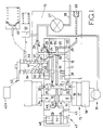
- Figure 1 is a diagrammatic part sectional view of the apparatus,
- Figure 2 is a view to an enlarged scale of a further part of the apparatus seen in Figure 1,
- Figure 3 is a sectional end view of a practical form of the apparatus,
- Figure 4 shows a detail of part of the apparatus seen in Figure 3,
- Figure 5 is a view in the opposite direction to that of Figure 3 showing the additional components for providing a load signal,
- Figure 6 is a diagram of the added hydraulic circuit,
- Figure 7 is a perspective view of one of the additional components, and
- Figure 8 is a perspective view showing another of the additional components.
- Referring to the drawings, the apparatus comprises a
body 10 in which is mounted afixed sleeve 11 defining a bore to receive a rotarycylindrical distributor member 12. The distributor member has an enlarged diameter portion projecting from the bore and in use is driven in timed relationship with an associated engine. - Formed in the enlarged portion of the distributor member is a
transverse bore 13 in which is mounted a pair ofpumping plungers 14 the outer ends of which engagecam followers 15 each cam follower comprising ashoe 16 and aroller 17. The rollers engage the internal peripheral surface of anannular cam ring 18 which is mounted within thebody 10. The angular position of the cam ring is adjustable by means of a fluid pressure operable springbiased piston 19, in known manner. - On the internal peripheral surface of the cam ring there is formed a plurality of pairs of cam lobes which extend from the base circle of the cam ring. As the distributor member rotates, the rollers engage with the leading flanks of the cam lobes to impart inward movement to the
pumping plungers 14. Thebore 13 is in communication with a longitudinal passage 20 which at one point communicates with a radially disposeddelivery passage 21 positioned to register in turn with a plurality ofoutlet ports 22 formed in the sleeve and extending tooutlets 23 respectively which are connected in use to the injection nozzles of the associated engine. - At another position the passage 20 is in communication with a plurality of radially disposed
inlet passages 24 which are positioned to register in turn withinlet ports 25 formed in thesleeve 11 and communicating by way of an on/offvalve 26, with the outlet of a low pressurefuel supply pump 27 having afuel inlet 28. Although not shown, the inlet and outlet of thesupply pump 27 are interconnected by way of a relief valve and the rotary part of the pump is coupled to the distributor member. By reason of the relief valve, the output pressure of thelow pressure pump 27 varies in accordance with the speed at which the distributor member is driven and theaforesaid piston 19 is subjected to the outlet pressure of the low pressure pump so that the angular setting of the cam ring depends upon the speed of the associated engine. - The
passage 21 is arranged to register with anoutlet port 22 during the whole time theplungers 14 are moved inwardly so that fuel displaced from thebore 13 can flow to the associated engine. As the distributor member rotates and as the rollers move over the crests of the cam lobes, thepassage 21 moves out of register with anoutlet port 22 and aninlet passage 24 moves into register with aninlet port 25. Fuel is therefore supplied to thebore 13 from the outlet of the low pressure pump and theplungers 14 are moved outwardly to their maximum extent so that the rollers engage the base circle of the cam ring. As described there is no method of controlling the quantity of fuel supplied through anoutlet 23. In order to achieve the desired control, there is provided a furthertransverse bore 29 in the enlarged portion of the distributor member and located in the bore is a pair of further orauxiliary plungers 30 the outer ends of which engage theshoes 16 so that the auxiliary plungers are moved inwardly at the same time as the pumping plungers. Thebore 29 is in constant communication with acircumferential groove 31 formed in the periphery of the distributor member and this groove is in constant communication with one end of a shuttle cylinder 32 which for convenience is defined by the bore of asleeve 33 which is angularly adjustable within thebody part 10 but is restrained from axial movement. Slidable within the shuttle cylinder 32 is ashuttle 34 which is biased as will be described, towards the one end of the cylinder. - Formed in the
sleeve 33 is a pair of axially spacedports port 36 is in constant communication with acircumferential groove 38 formed on the distributor member whilst theport 37 is in constant communication with aport 39 which is formed in the sleeve and which opens onto the periphery of the distributor member at a position to register with theinlet passages 24. The registration of theport 39 with aninlet passage 24 is arranged to occur during the time thepumping plungers 14 are moved inwardly. Theshuttle 34 is provided with agroove 40 which is in constant communication with theport 36 and extending from thegroove 40 is aninclined groove 41 which as will be explained, is positioned to register with theport 37 after a predetermined movement of the shuttle. The shuttle is angularly adjustable and for this purpose is provided with anarm 42 which is coupled to an actuating mechanism in the form of agovernor 42A. By moving theshuttle 34 angularly the extent of movement of the shuttle away from said one end of the cylinder before theport 37 is brought into register with thegroove 41, can be adjusted. - Also provided is a normally closed valve generally indicated at 43 and including a
piston 44 which is housed within acylinder 45 defined in an extension of thedistributor member 12. Thepiston 44 is integral with avalve member 46 which co-operates with a seating defined in the end wall of thecylinder 45, the seating being located at one end of apassage 47 which communicates with thebore 13. Thepiston 44 is biased by aspring 48 so that thevalve member 46 engages with theseating 48 and the spring is sufficiently strong to ensure that thevalve member 46 is held in sealing engagement with the seating. - Operation starts with the items in the positions shown in Figure 1 which corresponds to the commencement of inward movement of the
pumping plungers 14 and theauxiliary plungers 30. As the distributor member rotates theplungers 14 will displace fuel from thebore 13 and delivery of fuel to the associated engine will take place through anoutlet 23. At the same time theplungers 30 are moved inwardly and fuel is displaced into the inner end of the cylinder 32 containing theshuttle 34. The shuttle therefore starts to move against the action of the means biasing the shuttle and this movement will continue so long as the plungers are moved inwardly. At some point during the movement of the shuttle theport 37 is brought into register with thegroove 41 and fuel at the high pressure developed by theplungers 14 is supplied to the inner end of thecylinder 45 and this fuel acts upon thepiston 44 to urge the piston against the action of thespring 48. As soon as thepiston 44 starts to move, the valve member is lifted from its seating and the remaining fuel which is displaced by theplungers 14 can flow into thecylinder 45 through thepassage 47 thereby displacing thepiston 44 against the action of thespring 48. By varying the angular position of theshuttle 34 the extent of movement of the shuttle before theport 37 registers with thegroove 41 can be controlled and therefore the position during the inward movement of theplungers 14 at which thevalve 43 is opened. Thus by moving the shuttle angularly the quantity of fuel which can be supplied to the associated engine can be varied. As stated, thearm 42 is connected to the governor 42A which will be either of the so-called all-speed type or the so-called two-speed type. Thesleeve 33 can also be moved angularly and two ways of achieving this are illustrated. In the first case a fluid pressureoperable piston 59 is provided, the piston being spring biased against the action of the outlet pressure of the low pressure pump. By connecting the piston to thesleeve 33, so called torque control can be obtained. Another way of moving the sleeve is by means of an air pressureresponsive diaphragm 60 which is responsive to the pressure of air delivered to the associated engine, thepiston 59 and thediaphragm 60 can if desired, both be provided to control the position of the sleeve. - When the plungers complete their inward movement and the
rollers 17 move over the crests of the cam lobes, the plungers can move outwardly and fuel is returned from the one end of thecylinder 45 to thebore 13 by movement of thepiston 44 by thespring 48. However, since fuel may have been supplied to the associated engine, fuel is supplied through one of theinlet passages 24 to thebore 13 to ensure that the plungers move outwardly their maximum extent. Theshuttle 34 will also be urged towards the inner end of the cylinder 32 displacing fuel back to thebore 29. Any additional fuel which is required to make up for leakage, is supplied by means of auxiliary fillingports 61 connected to the outlet of the fuel supply pump and communicating at the appropriate time, with apassage 62 in the distributor member and which is in communication with thebore 29. Theplungers 30 are moved outwardly to their maximum extent. - Turning now to Figure 2 the outer end of the
shuttle 34 is engaged by ashuttle return piston 50 which is slidable in afurther cylinder 51. Also provided is anaccumulator chamber 52 which is in communication with thecylinder 51 by way of apassage 53 incorporating arestrictor 54. The accumulator chamber is in communication with the outlet of thelow pressure pump 27 by way of a oneway valve 55 and the accumulator chamber is in part defined by anaccumulator piston 56 which is spring biased by means of aspring 57 towards astop 58. The area of theaccumulator piston 56 is greater than that of theshuttle return piston 50 which in turn is larger than that of theshuttle 34. Moreover, thespring 57 is of sufficient strength so as to be able to hold theaccumulator piston 56 against thestop 58 against the force developed on the piston by the output pressure of thelow pressure pump 27. The area of contact between theshuttle 34 and thereturn piston 50 is minimised by making the presented surface of one of the components, in this case the shuttle, of convex form. - In operation, when the
auxiliary plungers 30 are moved inwardly theshuttle 34 will as described, be moved upwardly as shown in Figure 2, causing movement of theshuttle return piston 50 which in turn displaces fuel by way of a restrictor 54 into theaccumulator chamber 52. The accumulator piston moves to accommodate the fuel, away from thestop 58 by a lesser amount because of its larger area. When theauxiliary plungers 30 are allowed to move outwardly the fuel stored in the accumulator chamber is returned to thecylinder 51 and thepiston 50 together with theshuttle 34 are returned to the positions shown. When during the return motion the accumulator piston engages thestop 58 thenon-return valve 55 opens to allow fuel flow into theaccumulator chamber 52 to make up for any fuel which has leaked along the working clearances between thepistons passage 62 is brought into register with aport 61 and fuel at the outlet pressure of the low pressure pump is applied to the underside of the shuttle, there will still be a net force acting to urge theshuttle 34 and theshuttle return piston 50 downwardly in view of the larger diameter of thereturn piston 50, and since the space between theshuttle 34 and thereturn piston 50 is at a low pressure. The purpose of the restrictor 54 is to damp the movement of theshuttle 34 and theshuttle return piston 50, in particular to ensure that theshuttle 34 does not separate from the fuel column between the shuttle and theauxiliary plungers 30 and to ensure that theauxiliary plungers 30 remain under the control of the cam lobes. - By the arrangement described the forces which restrain angular movement of the
shuttle 34 are kept to a minimum. Furthermore thespring 57 although stronger than that which would be required to bias theshuttle 34 if it were applied directly to the shuttle, has to accommodate a reduced movement and is easier to design. - With reference now to Figure 3 of the drawings, the
body 10 is located within a housing or casing 9 which defines achamber 8 which is closed by a cover 7. The chamber contains fuel at low pressure. Theshuttle 34 andsleeve 33 extend into the chamber and within the chamber there is formed a locating surface 61A. Accommodated within the chamber is a support body 62A which is secured by screws to the portion of the casing which defines the locating surface 61A and astop bracket 63 of double "L" shaped form has one of its limbs interposed between the locating surface and the support body. The other limb of the stop bracket is apertured to allow theshuttle 34 to pass therethrough and the stop bracket is accurately located by means of adowel pin 64. This limb of the stop bracket on one face serves to locate thesleeve 33 and its other face serves as a stop face which is engageable by thearm 42 to limit the movement of theshuttle 34 into thesleeve 33. - The support body 62A carries a
flanged shaft 65 which is a press fit in the support body and angularly movable about the shaft and located between the flange thereof and the support body is alever 66 in which is mounted a dependingpin 67. Mounted about the pin is a roller 68 having a groove in which is located a governor link which forms what can be regarded as the output member of thegovernor mechanism 42A. Thepin 67 is also engaged with thearm 41 in such a manner that the arm can move axially relative to the pin as theshuttle 34 moves axially but movement of the pin with thelever 66 will impart angular movement to the shuttle. - The
flanged shaft 65 defines thecylinder 51 for theshuttle return piston 50 and the inner end of the cylinder by means of a cross drilling in the shaft which forms the restrictor 54, communicates with apassage 69 in the support body 62A. This passage is plugged at one end and is blind at its other end which by way of asleeve 70 communicates with afuel supply gallery 71 which in turn communicates with the outlet of thepump 27. A plate valve element is located between the end of thesleeve 70 and thepassage 69 to form thevalve 55. - The plugged end of the
passage 69 communicates with the inner end of theaccumulator chamber 52 which contains theaccumulator piston 56. Thespring 57 which biases the accumulator piston passes through an opening in thestop bracket 63 and into arecess 72 in the casing 9. The spring is provided with a hardened abutment which engages the base of the recess. The end wall of thechamber 52 serves as thestop 58 which limits the movement of the accumulator piston under the action of its spring and its movement in the opposite direction is limited by its engagement with thestop bracket 63. Moreover, therecess 72 communicates with thechamber 8 by way of a slot (not shown) to vent the underside of the piston. The apparatus functions as described previously. - Figure 4 shows a safety feature in the form of a
plate valve 74 which is interposed between theaccumulator piston 56 and itsspring 57 and which in the event that thepiston 56 sticks can open to prevent the development of excessive pressure as theplungers 30 move inwardly. - The timing of fuel delivery in the apparatus as described varies in accordance with the speed at which the associated engine is driven. In some cases it is desirable that the position of the cam ring should vary also in accordance with the amount of fuel which is being supplied to the engine. This is achieved by providing a further attachment to the apparatus.
- With reference to Figure 5 of the drawings, there is mounted on the upper surface of the support body 62A a
support arm 75 for avalve housing 76. Formed in the valve housing is anaxial bore 77 and slidable axially and movable angularly within the bore is acylindrical valve member 78 which is seen in perspective in Figure 7. The upper end of the valve member is domed and adjacent the lower end is agroove 79. A flat 80 is defined on a portion of the valve member which defines the base wall of the groove. Located in the groove is oneend portion 82 of aspring actuating arm 81 which is seen in perspective in Figure 8. The arm is formed from strip material such as spring steel and theaforesaid end portion 82 is hooked so as to form a clip whereby it is retained in the groove. Moreover the end portion includes aflat portion 84 which locates against the flat 80 of the valve member whereby the valve member can be moved angularly by the arm. Thearm 81 extends outwardly from the valve member and the strip is twisted through 90° and then is bent at right angles to define a dependinglimb 85. Thelimb 85 is located in arecess 86 in thelever 66 so that as the lever is moved angularly by the governor mechanism so also will be thevalve member 78. In addition, thearm 81 also imparts an upward axial thrust to the valve member which urges the domed upper end of the valve member into engagement with anadjustable stop 87 which is mounted in a modifiedcover 7A. - The
valve housing 76 and thevalve member 78 form apressure control valve 89 which is incorporated in an additional hydraulic circuit seen in Figure 6. The cylinder containing thetiming piston 19 instead of being connected directly to the output of thelow pressure pump 27 is connected thereto through anorifice 88 and the control valve controls the flow of fuel from downstream of the orifice to a drain. The orifice and valve therefore act as a fluid potentiometer and the greater the flow of fuel to the drain the greater the pressure drop across the orifice. - As seen in Figure 7 the
valve member 78 is formed with ahelical groove 90 which extends on opposite sides of arecess 91 the latter being either of square or circular shape. The recess through apassage 92 formed in thevalve housing 76 and thesupport body 75, communicates with the downstream side of theorifice 88. Moreover, formed in the valve body is aport 93 which opens onto the periphery of the valve member and communicates with thechamber 8. Theport 93 is positioned so that the degree of registration of thegroove 90 therewith varies as the valve member is moved angularly and at low and high fuel delivery levels the port is closed so that the pressure applied to thepiston 19 is the output pressure of thepump 27. As a result and assuming constant speed as the governor mechanism moves to increase the fuel delivery the pressure applied to thepiston 19 will fall as thegroove 90 moves into register with the port and then will increase as the groove moves out of register. The delivery of fuel will therefore be progressively retarded and then advanced. The normal speed advance will still be obtained since the output pressure of thepump 27 varies with speed. It is possible that the pressure applied to thepiston 19 may fall to an undesirable level and in order to avoid this a pressuredifferential valve 94 is connected in parallel with theorifice 88. - If instead of one port 93 a pair of such ports are provided and spaced by a distance corresponding to the width of the
groove 90, the opposite effect to that described is achieved if the groove is arranged to be uncovered to the one and the other port at low and high fuel delivery. - The provision of the
adjustable stop 87 allows the axial setting of thevalve member 78 to be adjusted following assembly of the apparatus and it will be appreciated that the shapes of the port or ports and the groove can be altered to obtain further shaping of the timing curve. - The construction of the
end portion 82 of thearm 81 allows the arm to continue to move with thelever 66 in the event that thevalve member 78 seizes in thebore 77 thereby allowing the governor mechanism to continue to control the operation of the engine. - In a modified construction of the
arm 81 the lower end of thelimb 85 is fashioned to a hollow cylindrical form and is engaged as a spring fit in a cylindrical recess in thelever 66. This provides more accurate location and improved stiffness in the direction of movement of the lever and arm.
Claims (12)
- A fuel pumping apparatus for supplying fuel to an internal combustion engine comprising a rotary distributor member (12) housed in a body (10) and driven in use in timed relationship with the associated engine, a bore (13) in the distributor member and a pumping plunger (14) therein, a cam (18) mounted in the body and defining a plurality of cam lobes which impart inward movement to the pumping plunger in turn as the distributor member rotates, a passage (21) connected with the bore (13) and which registers with outlet ports (22) in turn, means including a low pressure fuel pump (27) for feeding fuel to the bore (13) to effect full outward movement of the pumping plunger in the intervals between the inward movements thereof, a fluid pressure operable normally closed valve (43) which when open allows fuel to escape from the bore (13) during inward movement of the pumping plunger (14) to terminate delivery of fuel through an outlet, a further plunger (30) mounted in a further bore (29) and operable in synchronism with the pumping plunger (14), a shuttle (34) slidable in a cylinder (32), passage means connecting said further bore (29) to one end of the cylinder (32), means biasing the shuttle (34) to said one end of the cylinder, the shuttle being moved away from said one end of the cylinder by fuel displaced by said further plunger (30), said shuttle after a predetermined movement away from said one end of the cylinder causing the application of fluid under pressure to said valve (43) to open the valve, the shuttle (34) being movable angularly to vary the extent of said predetermined movement and an actuating mechanism (42A) for determining the angular setting of the shuttle characterised in that the means biasing the shuttle (34) comprises a shuttle return piston (50) slidable in a further cylinder (51) the piston (50) engaging the end of the shuttle (34) remote from said one end of the shuttle cylinder, the diameter of the shuttle return piston being slightly greater than that of the shuttle, an accumulator chamber (52) connected to the end of the further cylinder remote from the shuttle, a restrictor (54) for restricting the rate at which fluid can pass between the further cylinder (51) and the accumulator chamber (52) and said accumulator chamber being in part defined by a spring loaded piston (56) having an area which is greater than the area of the shuttle return piston (50).
- An apparatus according to Claim 1, characterised in that one of the shuttle return piston (50) and the shuttle (34) has a convex surface presented to the other.
- An apparatus according to Claim 1 or Claim 2, characterised by a non return valve (55) through which fluid can flow into said accumulator chamber (52) to make up any leakage.
- An apparatus according to Claim 3, characterised by valve means (74) through which fluid can escape from said accumulator chamber (52) in the event of sticking of the spring loaded piston (56).
- An apparatus according to Claim 4, characterised in that said valve means comprises a plate valve (74) which is biased by the spring (57) associated with the spring loaded piston (56) to cover an opening in said piston.
- An apparatus according to Claim 1, characterised in that said accumulator chamber (52) is formed in a part (62A) which is secured in a housing (9) of the apparatus, said part mounting a hollow shaft (65) which defines said further cylinder (51) and about which is mounted a lever (66) operatively connected to an output member of the actuating mechanism (42A) said lever (66) mounting a pin (67) which is engaged with an arm (42) carried by the shuttle (34).
- An apparatus according to Claim 6 characterised by a valve housing (76) adapted to be mounted on said part (62A), an adjustable valve member (78) mounted in said valve housing, means (81) coupling said valve member (78) to said lever (66), so that the valve member is moved therewith, said valve member and valve housing forming a valve which controls the pressure applied to a spring loaded piston (19) which is coupled to said cam (18).
- An apparatus according to Claim 7, characterised in that said valve member (78) is angularly adjustable in said valve housing (76) said coupling means comprising a spring actuating arm (81) having one end portion (82) clipped about a portion of the valve member, the arm extending outwardly from the valve member and then being bent substantially at right angles to define a depending limb (85) the end portion of which is located in a recess (86) in said lever (66).
- An apparatus according to Claim 8, characterised in that said arm (81) is formed from strip material the end portion (82) being located in a groove (79) in the valve member (78), said end portion including a flat portion (84) which locates against a flat (80) in the base wall of said groove.
- An apparatus according to Claim 9, characterised in that said valve member (78) is axially movable in the valve housing and is biased axially into engagement with an adjustable stop (87) by the resilience of said arm (81).
- An apparatus according to Claim 9, characterised in that said recess (86) is of cylindrical form and the depending limb (85) is fashioned to hollow cylindrical form.
- An apparatus according to Claim 10, characterised in that said valve member (78) is provided with a helical groove (90), a first port (92) formed in the valve housing and in constant communication with said groove, said first passage communicating with the outlet of the low pressure pump (27) by way of a fixed orifice (88), said first passage also communicating with the cylinder containing said piston (19) and a second port (93) in the valve housing, said second port being positioned to communicate with said groove depending upon the angular setting of the valve member (78) and communicating with a drain whereby the pressure applied to the piston (19) depends upon the setting of the shuttle.
Applications Claiming Priority (6)
| Application Number | Priority Date | Filing Date | Title |
|---|---|---|---|
| GB9103318 | 1991-02-16 | ||
| GB919103318A GB9103318D0 (en) | 1991-02-16 | 1991-02-16 | Fuel pumping apparatus |
| GB919114050A GB9114050D0 (en) | 1991-06-28 | 1991-06-28 | Fuel pumping action |
| GB9114050 | 1991-06-28 | ||
| GB9118318 | 1991-08-24 | ||
| GB919118318A GB9118318D0 (en) | 1991-08-24 | 1991-08-24 | Fuel pumping apparatus |
Publications (3)
| Publication Number | Publication Date |
|---|---|
| EP0500231A2 EP0500231A2 (en) | 1992-08-26 |
| EP0500231A3 EP0500231A3 (en) | 1992-11-25 |
| EP0500231B1 true EP0500231B1 (en) | 1994-11-02 |
Family
ID=27265515
Family Applications (1)
| Application Number | Title | Priority Date | Filing Date |
|---|---|---|---|
| EP92300967A Expired - Lifetime EP0500231B1 (en) | 1991-02-16 | 1992-02-05 | Fuel pumping apparatus |
Country Status (4)
| Country | Link |
|---|---|
| US (1) | US5213481A (en) |
| EP (1) | EP0500231B1 (en) |
| DE (1) | DE69200594T2 (en) |
| ES (1) | ES2066556T3 (en) |
Families Citing this family (3)
| Publication number | Priority date | Publication date | Assignee | Title |
|---|---|---|---|---|
| GB9420254D0 (en) * | 1994-10-07 | 1994-11-23 | Lucas Ind Plc | Fuel injection pump |
| JP4305459B2 (en) * | 2006-02-27 | 2009-07-29 | トヨタ自動車株式会社 | Fuel supply device for internal combustion engine |
| NO327431B1 (en) * | 2006-09-08 | 2009-06-29 | Yara Int Asa | Method and apparatus for trapping platinum group elements |
Family Cites Families (5)
| Publication number | Priority date | Publication date | Assignee | Title |
|---|---|---|---|---|
| ZA791180B (en) * | 1978-03-22 | 1980-03-26 | Lucas Industries Ltd | Liquid fuel injection pump |
| GB8828159D0 (en) * | 1988-12-02 | 1989-01-05 | Lucas Ind Plc | Fuel injection pump |
| EP0381343B1 (en) * | 1989-01-28 | 1992-12-16 | Lucas Industries Public Limited Company | Fuel pumping apparatus |
| GB8903683D0 (en) * | 1989-02-17 | 1989-04-05 | Lucas Ind Plc | Fuel pumping apparatus |
| GB8926477D0 (en) * | 1989-11-23 | 1990-01-10 | Lucas Ind Plc | Fuel pumping apparatus |
-
1992
- 1992-02-05 DE DE69200594T patent/DE69200594T2/en not_active Expired - Fee Related
- 1992-02-05 ES ES92300967T patent/ES2066556T3/en not_active Expired - Lifetime
- 1992-02-05 EP EP92300967A patent/EP0500231B1/en not_active Expired - Lifetime
- 1992-02-07 US US07/832,817 patent/US5213481A/en not_active Expired - Fee Related
Also Published As
| Publication number | Publication date |
|---|---|
| ES2066556T3 (en) | 1995-03-01 |
| EP0500231A3 (en) | 1992-11-25 |
| DE69200594T2 (en) | 1995-03-30 |
| EP0500231A2 (en) | 1992-08-26 |
| DE69200594D1 (en) | 1994-12-08 |
| US5213481A (en) | 1993-05-25 |
Similar Documents
| Publication | Publication Date | Title |
|---|---|---|
| US4432327A (en) | Timing control for fuel injection pump | |
| EP0039304B2 (en) | Apparatus for adjusting the timing of a fuel injection pump | |
| US3943902A (en) | Fuel injection pumping apparatus | |
| US4074667A (en) | Liquid fuel injection pumping apparatus | |
| CA1065705A (en) | Timing control for fuel injection pump | |
| US5611317A (en) | Open nozzle fuel injector having drive train wear compensation | |
| US4079719A (en) | Timing control for fuel pump | |
| US4014305A (en) | Fuel injection pumping apparatus | |
| US3648673A (en) | Fuel injection pump | |
| US4080109A (en) | Fuel injection pumping apparatus | |
| US3447520A (en) | Liquid fuel pumping apparatus | |
| EP0364076B1 (en) | Fuel pumping apparatus | |
| US4550702A (en) | Spill control system for distributor pump | |
| US5213481A (en) | Fuel pumping apparatus | |
| US4146003A (en) | Fuel injection pumping apparatus with drain passage | |
| US4936755A (en) | Fuel injection pumping apparatus | |
| US3557764A (en) | Liquid fuel pumping apparatus | |
| US3936232A (en) | Fuel injection pumping apparatus with timing adjustment | |
| US4019835A (en) | Liquid fuel injection pumping apparatus | |
| US5138999A (en) | Fuel pumping apparatus | |
| EP0644327B1 (en) | Fuel pump | |
| US5207202A (en) | Fuel pumping apparatus | |
| US5203303A (en) | Fuel pumping apparatus | |
| US4353343A (en) | Fuel injection pump for internal combustion engines | |
| US4325676A (en) | Liquid fuel pumping apparatus |
Legal Events
| Date | Code | Title | Description |
|---|---|---|---|
| PUAI | Public reference made under article 153(3) epc to a published international application that has entered the european phase |
Free format text: ORIGINAL CODE: 0009012 |
|
| AK | Designated contracting states |
Kind code of ref document: A2 Designated state(s): DE ES FR GB IT |
|
| PUAL | Search report despatched |
Free format text: ORIGINAL CODE: 0009013 |
|
| AK | Designated contracting states |
Kind code of ref document: A3 Designated state(s): DE ES FR GB IT |
|
| 17P | Request for examination filed |
Effective date: 19930331 |
|
| 17Q | First examination report despatched |
Effective date: 19940318 |
|
| GRAA | (expected) grant |
Free format text: ORIGINAL CODE: 0009210 |
|
| AK | Designated contracting states |
Kind code of ref document: B1 Designated state(s): DE ES FR GB IT |
|
| ITF | It: translation for a ep patent filed | ||
| REF | Corresponds to: |
Ref document number: 69200594 Country of ref document: DE Date of ref document: 19941208 |
|
| ET | Fr: translation filed | ||
| REG | Reference to a national code |
Ref country code: ES Ref legal event code: FG2A Ref document number: 2066556 Country of ref document: ES Kind code of ref document: T3 |
|
| PLBE | No opposition filed within time limit |
Free format text: ORIGINAL CODE: 0009261 |
|
| 26N | No opposition filed | ||
| PGFP | Annual fee paid to national office [announced via postgrant information from national office to epo] |
Ref country code: GB Payment date: 19970127 Year of fee payment: 6 |
|
| PGFP | Annual fee paid to national office [announced via postgrant information from national office to epo] |
Ref country code: FR Payment date: 19970211 Year of fee payment: 6 |
|
| PGFP | Annual fee paid to national office [announced via postgrant information from national office to epo] |
Ref country code: DE Payment date: 19970214 Year of fee payment: 6 |
|
| PGFP | Annual fee paid to national office [announced via postgrant information from national office to epo] |
Ref country code: ES Payment date: 19970227 Year of fee payment: 6 |
|
| PG25 | Lapsed in a contracting state [announced via postgrant information from national office to epo] |
Ref country code: GB Free format text: LAPSE BECAUSE OF NON-PAYMENT OF DUE FEES Effective date: 19980205 |
|
| PG25 | Lapsed in a contracting state [announced via postgrant information from national office to epo] |
Ref country code: ES Free format text: LAPSE BECAUSE OF EXPIRATION OF PROTECTION Effective date: 19980206 |
|
| PG25 | Lapsed in a contracting state [announced via postgrant information from national office to epo] |
Ref country code: FR Free format text: THE PATENT HAS BEEN ANNULLED BY A DECISION OF A NATIONAL AUTHORITY Effective date: 19980228 |
|
| GBPC | Gb: european patent ceased through non-payment of renewal fee |
Effective date: 19980205 |
|
| PG25 | Lapsed in a contracting state [announced via postgrant information from national office to epo] |
Ref country code: DE Free format text: LAPSE BECAUSE OF NON-PAYMENT OF DUE FEES Effective date: 19981103 |
|
| REG | Reference to a national code |
Ref country code: FR Ref legal event code: ST |
|
| REG | Reference to a national code |
Ref country code: ES Ref legal event code: FD2A Effective date: 20000601 |
|
| PG25 | Lapsed in a contracting state [announced via postgrant information from national office to epo] |
Ref country code: IT Free format text: LAPSE BECAUSE OF NON-PAYMENT OF DUE FEES;WARNING: LAPSES OF ITALIAN PATENTS WITH EFFECTIVE DATE BEFORE 2007 MAY HAVE OCCURRED AT ANY TIME BEFORE 2007. THE CORRECT EFFECTIVE DATE MAY BE DIFFERENT FROM THE ONE RECORDED. Effective date: 20050205 |