EP0499367B1 - Electromagnetic reciprocating pump - Google Patents
Electromagnetic reciprocating pump Download PDFInfo
- Publication number
- EP0499367B1 EP0499367B1 EP92300606A EP92300606A EP0499367B1 EP 0499367 B1 EP0499367 B1 EP 0499367B1 EP 92300606 A EP92300606 A EP 92300606A EP 92300606 A EP92300606 A EP 92300606A EP 0499367 B1 EP0499367 B1 EP 0499367B1
- Authority
- EP
- European Patent Office
- Prior art keywords
- piston
- main shaft
- casing
- reciprocating pump
- armature
- Prior art date
- Legal status (The legal status is an assumption and is not a legal conclusion. Google has not performed a legal analysis and makes no representation as to the accuracy of the status listed.)
- Expired - Lifetime
Links
Images
Classifications
-
- F—MECHANICAL ENGINEERING; LIGHTING; HEATING; WEAPONS; BLASTING
- F04—POSITIVE - DISPLACEMENT MACHINES FOR LIQUIDS; PUMPS FOR LIQUIDS OR ELASTIC FLUIDS
- F04B—POSITIVE-DISPLACEMENT MACHINES FOR LIQUIDS; PUMPS
- F04B17/00—Pumps characterised by combination with, or adaptation to, specific driving engines or motors
- F04B17/03—Pumps characterised by combination with, or adaptation to, specific driving engines or motors driven by electric motors
- F04B17/04—Pumps characterised by combination with, or adaptation to, specific driving engines or motors driven by electric motors using solenoids
-
- F—MECHANICAL ENGINEERING; LIGHTING; HEATING; WEAPONS; BLASTING
- F04—POSITIVE - DISPLACEMENT MACHINES FOR LIQUIDS; PUMPS FOR LIQUIDS OR ELASTIC FLUIDS
- F04B—POSITIVE-DISPLACEMENT MACHINES FOR LIQUIDS; PUMPS
- F04B53/00—Component parts, details or accessories not provided for in, or of interest apart from, groups F04B1/00 - F04B23/00 or F04B39/00 - F04B47/00
- F04B53/08—Cooling; Heating; Preventing freezing
-
- F—MECHANICAL ENGINEERING; LIGHTING; HEATING; WEAPONS; BLASTING
- F04—POSITIVE - DISPLACEMENT MACHINES FOR LIQUIDS; PUMPS FOR LIQUIDS OR ELASTIC FLUIDS
- F04B—POSITIVE-DISPLACEMENT MACHINES FOR LIQUIDS; PUMPS
- F04B17/00—Pumps characterised by combination with, or adaptation to, specific driving engines or motors
- F04B17/03—Pumps characterised by combination with, or adaptation to, specific driving engines or motors driven by electric motors
- F04B17/04—Pumps characterised by combination with, or adaptation to, specific driving engines or motors driven by electric motors using solenoids
- F04B17/046—Pumps characterised by combination with, or adaptation to, specific driving engines or motors driven by electric motors using solenoids the fluid flowing through the moving part of the motor
Definitions
- the present invention is related to an electromagnetic reciprocating pump, and particularly to an electromagnetic reciprocating pump which enables the piston drive section to be cooled with a simple structure and can be manufactured at a low cost.
- the present invention is related to an electromagnetic reciprocating pump wherein the piston drive section can effectively be cooled and the armature provided in the piston can be made lightweight.
- the electromagnetic reciprocating pump is publicly known in which a fluid is repetitively sucked and discharged by displacing a piston having a piston head slidably disposed in a cylinder in one direction by means of a spring, and periodically attracting the piston in the direction opposite to the above-mentioned direction by means of an electromagnet, which is disposed in a casing so that a plurality of magnetic poles are positioned outside of the armature provided in the piston, thereby to reciprocating the piston.
- the opening for introducing air is communicating with a pressure chamber with the shortest distance, and thus the frictional heat between the piston and the main shaft for the piston, the Joule heat and the heat due to iron loss in the electromagnetic circuit or the like are not fully dissipated. Even if a port or introducing the cooling air is provided in the rear part of the casing, the cooling effect of the introduced air in the casing is not sufficient because of the closed-type casing and the heat is confined within the casing, which causes a problem that the main shaft temperature increased and the reciprocating motion becomes uneven because of thermal expansion or distortion.
- EP-A-0,014,817 Another construction of electromagnetic reciprocating pump designed to address the problems associated with an imbalance between the magnetic action between the magnetic poles of the electromagnet and the armature is disclosed in EP-A-0,014,817.
- an electromagnetic fluid pump such as an air pump, in which a piston assembly carrying an armature is reciprocated axially by the operative combination of magnetic attraction generated by a stator core and mechanical spring repulsion for cyclic discharge of the fluid from a piston chamber.
- the piston assembly is positively supported on both axial sides of the stator core and a pneumatic spring is incorporated into the piston assembly. Biased movement of the piston assembly and bias in the magnetic attraction are both prevented in order to minimise undesirable abrasion of the piston assembly and the related parts thereof.
- a further construction of electromagnetic fluid operating apparatus such as an air compressor, is disclosed in US-A-4,090,816.
- a piston with an armature axially reciprocates along a path substantially at a right angle to the magnetic flux generated by a stator core due to alternate operation by electromagnetic attraction and mechanical repulsion. Collimations are established between the armature and the stator core and between the piston and a cylinder for the piston when they are assembled together thereby minimising biased frictional abrasion of coacting sliding surfaces.
- An internal air reservoir is provided at the air outlet terminal in order to reduce pulsation of air supplied by the apparatus.
- an electromagnetic reciprocating pump comprising: a closed-type casing provided with a cylinder in the front end thereof, a main shaft the front end of which is fixed to and supported on the front wall of said cylinder, and which main shaft is disposed so that the central axis thereof matches that of said cylinder, a piston having a piston head in the front end thereof, fitted over the outer peripheral surface of said main shaft so that said piston head reciprocates in said cylinder, and having an armature fixed and held thereon, a spring disposed between said piston and casing for biasing said piston in one direction, an electromagnet fixed within said casing for attracting said piston and armature in the opposite direction against the biasing force of said spring, a pressure chamber defined by said cylinder and piston head, and a suction port, a suction valve, a discharge port and a discharge valve of a fluid provided in said cylinder and piston head, respectively, wherein said main shaft is a hollow cylindrical body having both ends opened, and fluid flows in a path of the hollow
- the electromagnet for attracting the armature is of a multipolar structure and has a plurality of, preferably, an even number equal to four or larger of magnetic poles, and a coil is wound around each of at least every other magnetic poles so that a closed magnetic path is formed between the adjacent two magnetic poles through the armature and york.
- an inlet port for introducing the fluid is provided so as to open to the side of the intial position of the piston biased by the spring, the main shaft is formed into a hollow cylinder and the inside and outside of the casing communicate with each other through the central through hole of the hollow main shaft and the inlet port, and the piston is provided with the suction ports and suction valves for sucking the fluid into the pressure chamber, whereby the fluid introduced into the casing can be guided to the rear part of the casing through the internal passage of the hollow main shaft, thereafter caused to pass by the electromagnet and armature, and then introduced into the suction ports of the piston.
- the fluid introduced into the closed casing is not directly introduced into the pressure chamber, but guided to the internal passage of the hollow main shaft, and caused to pass through the hollow main shaft in the axial direction to cool it, thereby preventing the temperature of the hollow main shaft itself from increasing.
- the fluid having passed through the hollow main shaft may then be guided around the electromagnetic circuit arranged on the outer periphery of the hollow main shaft cooling the electromagnetic circuit to suppress its temperature increase, and thereafter may be guided into the pressure chamber to be compressed and discharged as in the conventional electromagnetic reciprocating pump.
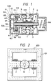
- coils 2 are wound around a plurality of magnetic poles 1 to form electromagnets, and the york of each magnetic pole is airtightly pinched and fixed between a front casing 3 having cylinder 3A in the front end thereof and a rear casing 4, thereby forming a closed casing.
- the electromagnets are radially disposed in substantially the central part of the closed casing and around a piston 6 to be described later.
- the electromagnets may be fixed to and supported on the inner wall of the casing.
- a hollow main shaft 5 is fixed to the front casing 3 so that its central axis coincides with the central axis of the cylinder 3A formed in the front end of the front casing 3.
- a front opening 5F of the hollow main shaft 5 is located at a position of substantially the shortest distance from an opening 52 formed in a front face of a cover 51 for introducing air, and allows the outside air to be introduced into a fluid passage 5A in the hollow main shaft 5.
- a rear opening 5B of the fluid passage 5A is open to the internal space of the rear casing 4, and the sucked air flows in fluid passage 5A from the front end to the rear end.
- fins for heat dissipation of the hollow main shaft 5 are formed axially of the main shaft, and the introduced air flows between the fins toward the rear opening 5B.
- the fins may be integrally formed in the fluid passage 5A of the main shaft 5, or may be formed by embedding the separately formed ones in the inner surface of the fluid passage 5A in a thermally contact state.
- the piston 6 having a piston head 6A is slidably fitted over the outer peripheral surface of the hollow main shaft 5.
- a sliding bearing 7 is preferably provided between the outer peripheral surface of the main shaft 5 and the inner peripheral surface of the piston 6 for reciprocating piston 6 more smoothly.
- a sliding bearing 6D is also preferably disposed between the inner peripheral surface of the cylinder 3A and the piston head 6A, but they may be airtightly contacted with each other with a very small gap.
- a pressure chamber 12 is defined by the cylinder 3A and piston head 6A.
- the piston head 6A is provided with a suction port 6B which is open to the direction of electromagnets 1 or to the internal space of the casing, and the suction port 6B is closed by a suction valve 6C. Since Fig. 1 shows the state in the moment when the piston 6 has started the forward motion, a suction valve 6C is open.
- a discharge port 13 is provided in the side wall portion of the cylinder 3A, and the discharge port 13 is closed by a discharge valve 14. The discharge valve 14 is closed when the piston 6 forwardly moves, but for convenience of explanation, it is shown in Fig. 1 as opened.
- An armature 8 attached to (substantially the center) of the piston 6 may integrally be assembled, for instance, when the piston is manufactured by aluminium die casting.
- a compression coil spring 9 is located between the piston 6 and the rear end surface of the rear casing 4 and on the same central axis as that of the piston 6.
- the end of the compression coil spring 9 on the piston 6 side is fixed to the piston 6, while the opposite end of the spring on the rear casing 4 is supported for rotation around the central axis of the piston 6 by a thrust ball bearing (not shown) fixed to the inner wall portion of the rear end of the rear casing 4, or a similar rotatable ring, and when the piston 6 rotates within the cylinder 3A, the compression spring 9 can also rotate therewith in the same direction.
- the cover 51 for forming a closed tank 51B and a port 51A for introducing air is attached so as to surround the discharge port 13 and the cylinder portion.
- a fluid discharge port 53 communicating with a consumption source (not shown) of the pressurized air is formed in the closed tank 51B.
- the opening 52 for introducing air which is not always necessary, is facing the opening 5F of the hollow main shaft 5 with the shortest distance.
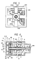
- Fig. 2 is a side view of a field core 100 having only single pair of magnetic poles 1 and an armature 8, which can be used for the electromagnetic reciprocating pump of Fig. 1.
- the field core 100 has a york 101 forming a closed magnetic path, and a pair of magnetic poles 1 inwardly projecting radially therefrom to the armature 8 positioned in the center.
- a coil 2 is wound around each of magnetic poles 1.
- the flows of magnetic flux are shown by broken arrow line, and the piston, main shaft and the like which are to be placed within armature 8 are omitted.
- the air introduced into the enclosed casing is further introduced into the pressure chamber 12 through the suction port 6B and the suction valves 6C.
- the air introduced into the pressure chamber 12 is pressurized in the same chamber at the time of the next leftward motion of the piston 6, opens the discharge valve 14 when the pressure in the chamber 12 has reached a set pressure and is discharged into the closed tank 51B through the discharge port 13 and the discharge valve 14, and then is discharged to the consumption source via the fluid discharge port 53.
- the mounting of the piston to the armature is accomplished by fitting into a casting mold an armature consisting of a plurality of laminated donut-like thin plates of a magnetic material, and thereafter injecting molten aluminium or the like to cast a piston.
- the piston 6 required a through hole having a relatively large diameter because it is fitted over the hollow main shaft 5, and/or because of load limitation per unit area of the sliding bearing 7 disposed between the piston and the main shaft.
- the armature 8 mounted on the outer periphery of the piston also required a hole having a diameter larger than the through hole. If the diameter of the hole of the armature 8 is too large, the outer diameter of armature also necessarily becomes larger, and the armature and hence the electromagnetic reciprocating pump undesirably becomes large-sized and heavyweight.
- Fig. 3 is a partly sectional side view of the field core and armature which were designed so as to be used more advantageously in the electromagnetic reciprocating pump of Fig. 1 and to address the above described problems.
- the piston 6, sliding bearings 7 and main shaft 5 are shown in cross section, and the coils 2 wound around the magnetic poles 1 are shown in a simplified form.
- the field core 100 has two pairs of magnetic poles 1 and 1K which are radially projecting inwardly form the york 101 and opposed to each other on a straight line, and the coils 2 and 2K are wound around the individual magnetic poles 1 and 1K.
- the coils 2 are wound so that a magnetic flux forms a closed loop through the armature 8 between any of the adjacent magnetic poles 1 and 1K, as shown by broken arrow lines in the figure.
- the sectional area of the armature 8 (the sectional area in a plane perpendicular to the direction in which the magnetic flux passes, or in a plane perpendicular to the paper surface) can be only 1/2.
- the attraction force is the same if the total magnetic flux ⁇ is the same. Accordingly, as compared with single pair of magnetic poles of Fig. 2, if two pairs of magnetic poles are provided as shown in Fig. 3, the total magnetic flux ⁇ passing through each magnetic pole only needs to be 1/2 to obtain the same attraction force.
- the sectional area of the armature 8 only needs to be 1/2 of the case of Fig. 2 as well.
- the sectional area of magnetic poles 1 only needs to be 1/2.
- the outer diameter of the armature 8 is the same, its inner diameter can be larger.
- the armature 8 is light-weight, but also the thickness from the inner wall of the armature 8 to the inner wall of the piston 6, namely, the thickness of the piston can be relatively large, whereby the piston 6 can be provided with sufficiently large strength.
- the diameter of the main shaft 5 can also be larger, the abrasion of the sliding bearing 7 can be reduced.
- the inner diameter of the armature is the same, its outer diameter can be smaller.
- the field core 100 shown in Fig. 3 consists of the rectangular york 101 and the two pairs of magnetic poles 1 and 1K formed so as to inwardly project from the york 101.
- the coils 2 and 2K are wound around the magnetic poles, it is technically difficult to directly wind a coil around each magnetic pole as shown and the space factor is low. Consequently, it may be preferable to previously wind a coil around a bobbin and insert the bobbin which the coil has been wound around into the magnetic pole 1.
- FIG. 4 is a partly sectional side view of an electromagnet device, which shows an example in which one of two pairs of magnetic poles are removable from the york of the field core.
- a field core 200 comprises a substantially square-shaped york 201 and a pair of magnetic poles 202 which are inwardly projecting from the centers of a pair of the subtenses of the york 201, and it is provided with a pair of recesses 204 in each center of the remaining pair of the subtenses.
- a pair of magnetic poles 203 having convex portions 203A of substantially the same shape as the recesses 204 are fitted, respectively, whereby a magnetic pole arrangement which is essentially the same as Fig. 3 is obtained.
- the bobbins 85 having the coils 2 wound around them can be very easily fitted over the magnetic poles 203 from a direction perpendicular to the paper surface.
- Fig. 5 shows an example in which the coils are conically wound, and for instance, one bobbin 86 has two sections in which two coils (coils 2A and 2B) of different outer diameter sized are wound around. And the other bobbin 87 has three sections in which three coils (coils 2C to 2E) of different outer diameter sized are wound around.
- the coil can be wound effectively in the shape of a cone.
- coils are shown to be wound around only two of the four magnetic poles in Fig. 5, coils are naturally be mounted on all of the four magnetic poles, respectively, as in Fig. 4.
- bobbins of the same shape may be used for all the magnetic poles, or bobbins of different shapes may be used.
- coils are wound around all of the four magnetic poles in the above description, for instance, coils may be wound around the every other magnetic poles.
- a pair of magnetic poles having no coil wound around them are provided right above and below armature 8 and the directions of the magnetic fluxes generating in the two coils 2 are made opposite to each other.
- the number of magnetic poles is not limited to four, but it may be an even number equal to four or greater. Also in this case, if a magnetic flux forms closed loops through the armature between each of adjacent magnetic poles, it is not required to wind a coil around all the magnetic poles, but coils may be wound around every other magnetic poles.
- the york may be in the shape of a cylinder.
- Fig. 6 is a cross-sectional view of another embodiment of the present invention in which both ends of the hollow main shaft are supported, and the same symbols as Fig. 1 represent the same or identical portions.
- the rear end of the fluid passage 5A within the hollow main shaft 15 is closed, and supported by the rear casing 4.
- a rear end opening 15B is formed in the rear end side of the fluid passage 5A.
- the fluid passes in the fluid passage 5A via the opening 52 for introducing air and the front end opening 15F, and is discharged via the rear end opening 15B into the closed casing.
- the main shaft 15 is supported at both ends thereof as described above, if the main shaft 15, front casing 3 and rear casing 4 are formed of electrically conductive material, an induced current may flow in a closed circuit consisting of the main shaft 15, front casing 3 and rear casing 4 by the magnetic flux generated from magnetic poles 1 when the coils are energized. In orer to prevent this current, it is desirable to dispose an electrical insulating material in part of the closed circuit. In the example of Fig. 6, an electrical insulator 16 is inserted between the joint surfaces of the magnetic poles 1 and rear casing 4.
- the fluid sucked into the air introducing chamber 51A is discharged from the discharge port 53 through the fluid passage 5A, inside of the casing, pressure chamber 12 and closed tank 51B.
- the direction of the fluid flow in the pump may be reversed. That is, it is possible that the directions of the suction valves, discharge valve and the like are reversed, and the fluid is sucked from the closed tank 51B (in this case, not closed) and the pressurized fluid is discharged from the air introducing chamber 51A (in this case, it should be closed).
- This has an advantage that the pulsation of the pressurized fluid is smoothed by the resistance of the fluid passage 5A.
Landscapes
- Engineering & Computer Science (AREA)
- Mechanical Engineering (AREA)
- General Engineering & Computer Science (AREA)
- Physics & Mathematics (AREA)
- Fluid Mechanics (AREA)
- Electromagnetic Pumps, Or The Like (AREA)
- Compressors, Vaccum Pumps And Other Relevant Systems (AREA)
Description
- The present invention is related to an electromagnetic reciprocating pump, and particularly to an electromagnetic reciprocating pump which enables the piston drive section to be cooled with a simple structure and can be manufactured at a low cost.
- In addition, the present invention is related to an electromagnetic reciprocating pump wherein the piston drive section can effectively be cooled and the armature provided in the piston can be made lightweight.
- The electromagnetic reciprocating pump is publicly known in which a fluid is repetitively sucked and discharged by displacing a piston having a piston head slidably disposed in a cylinder in one direction by means of a spring, and periodically attracting the piston in the direction opposite to the above-mentioned direction by means of an electromagnet, which is disposed in a casing so that a plurality of magnetic poles are positioned outside of the armature provided in the piston, thereby to reciprocating the piston. In the prior art electromagnetic reciprocating pump, if the magnetic action between the magnetic poles of the electromagnet and the armature becomes unbalanced even in very small amount, then the armature is moved to a magnetic pole side where the magnetic action is stronger, so that the piston may be partially abraded or broken. As a countermeasure for that, it is known to make the axis of the piston match the center line of the corresponding plural magnetic poles. An example of it is disclosed in the Japanese Utility Model Publication No.(Y2)57-47437 which is known as an invention providing a remarkable effect of axes alignment.
- In accordance with the electromagnetic reciprocating pump disclosed in the aforementioned publication, the opening for introducing air is communicating with a pressure chamber with the shortest distance, and thus the frictional heat between the piston and the main shaft for the piston, the Joule heat and the heat due to iron loss in the electromagnetic circuit or the like are not fully dissipated. Even if a port or introducing the cooling air is provided in the rear part of the casing, the cooling effect of the introduced air in the casing is not sufficient because of the closed-type casing and the heat is confined within the casing, which causes a problem that the main shaft temperature increased and the reciprocating motion becomes uneven because of thermal expansion or distortion.
- It is also disclosed in the Japanese publication that, when the piston is supported on the main shaft, a sliding bearing of a small coefficient is fitted over the main shaft to expect a smooth reciprocating motion of the piston, but there is a problem that the life of the sliding bearing is adversely affected by such temperature increase of the main shaft as described above and shortened.
- Further, there is a problem that, since the magnetic poles of the field core opposite to the armature are of only one pair, it is difficult to reduce the sectional area of the armature thereby for making the armature small size and lightweight.
- Another construction of electromagnetic reciprocating pump designed to address the problems associated with an imbalance between the magnetic action between the magnetic poles of the electromagnet and the armature is disclosed in EP-A-0,014,817. In this document there is described an electromagnetic fluid pump, such as an air pump, in which a piston assembly carrying an armature is reciprocated axially by the operative combination of magnetic attraction generated by a stator core and mechanical spring repulsion for cyclic discharge of the fluid from a piston chamber. The piston assembly is positively supported on both axial sides of the stator core and a pneumatic spring is incorporated into the piston assembly. Biased movement of the piston assembly and bias in the magnetic attraction are both prevented in order to minimise undesirable abrasion of the piston assembly and the related parts thereof.
- A further construction of electromagnetic fluid operating apparatus, such as an air compressor, is disclosed in US-A-4,090,816. In this construction a piston with an armature axially reciprocates along a path substantially at a right angle to the magnetic flux generated by a stator core due to alternate operation by electromagnetic attraction and mechanical repulsion. Collimations are established between the armature and the stator core and between the piston and a cylinder for the piston when they are assembled together thereby minimising biased frictional abrasion of coacting sliding surfaces. An internal air reservoir is provided at the air outlet terminal in order to reduce pulsation of air supplied by the apparatus.
- Yet a further construction of electromagnetic reciprocating motor is disclosed in FR-A-842,073 in which a piston is mounted on a main shaft having a hollow portion, the hollow portion defining a fluid path therethrough.
- It is an object of the present invention to provide an electromagnetic reciprocating pump which causes less main shaft temperature increase, less reduction in the compression/attraction efficiency, and less abrasion of the piston bearing.
- It is another object of the present invention to provide an electromagnetic reciprocating pump in which the sectional area of the armature can be made smaller to make the armature small size and lightweight, and the hole diameter of the armature can be enlarged without increasing the outer diameter thereof.
- According to the present invention there is provided an electromagnetic reciprocating pump comprising: a closed-type casing provided with a cylinder in the front end thereof, a main shaft the front end of which is fixed to and supported on the front wall of said cylinder, and which main shaft is disposed so that the central axis thereof matches that of said cylinder, a piston having a piston head in the front end thereof, fitted over the outer peripheral surface of said main shaft so that said piston head reciprocates in said cylinder, and having an armature fixed and held thereon, a spring disposed between said piston and casing for biasing said piston in one direction, an electromagnet fixed within said casing for attracting said piston and armature in the opposite direction against the biasing force of said spring, a pressure chamber defined by said cylinder and piston head, and a suction port, a suction valve, a discharge port and a discharge valve of a fluid provided in said cylinder and piston head, respectively, wherein said main shaft is a hollow cylindrical body having both ends opened, and fluid flows in a path of the hollow portion of said main shaft, the space between said piston and casing, said suction ports, suction valves, pressure chamber, discharge port and discharge valve.
- Advantageously the electromagnet for attracting the armature is of a multipolar structure and has a plurality of, preferably, an even number equal to four or larger of magnetic poles, and a coil is wound around each of at least every other magnetic poles so that a closed magnetic path is formed between the adjacent two magnetic poles through the armature and york.
- In a preferred arrangement an inlet port for introducing the fluid is provided so as to open to the side of the intial position of the piston biased by the spring, the main shaft is formed into a hollow cylinder and the inside and outside of the casing communicate with each other through the central through hole of the hollow main shaft and the inlet port, and the piston is provided with the suction ports and suction valves for sucking the fluid into the pressure chamber, whereby the fluid introduced into the casing can be guided to the rear part of the casing through the internal passage of the hollow main shaft, thereafter caused to pass by the electromagnet and armature, and then introduced into the suction ports of the piston.
- Advantageously the fluid introduced into the closed casing is not directly introduced into the pressure chamber, but guided to the internal passage of the hollow main shaft, and caused to pass through the hollow main shaft in the axial direction to cool it, thereby preventing the temperature of the hollow main shaft itself from increasing. The fluid having passed through the hollow main shaft may then be guided around the electromagnetic circuit arranged on the outer periphery of the hollow main shaft cooling the electromagnetic circuit to suppress its temperature increase, and thereafter may be guided into the pressure chamber to be compressed and discharged as in the conventional electromagnetic reciprocating pump.
- An embodiment of the present invention will now be described by way of example with reference to the accompanying drawings in which:
- Figure 1 is a schematic logitudinal sectional view showing an embodiment of the present invention.
- Figure 2 is a side view of the field core having only a single pair of magnetic poles and the armature core which can be used for the electromagnetic reciprocating pump shown in Fig. 1.
- Fig. 3 is a partly sectional side view of the field core and armature
- Fig. 4 is a partly sectional side view of an electromagnet in which one of the two pairs of magnetic poles are constructed to be removable from the york of the field core.
- Fig. 5 is a partly sectional view of the electromagnet for showing the shape of the bobbins for winding the coil in substantially the shape of a conical form.
- Fig.6 is a cross-sectional view of another embodiment of the present invention.
- In Fig. 1,
coils 2 are wound around a plurality of magnetic poles 1 to form electromagnets, and the york of each magnetic pole is airtightly pinched and fixed between afront casing 3 havingcylinder 3A in the front end thereof and arear casing 4, thereby forming a closed casing. The electromagnets are radially disposed in substantially the central part of the closed casing and around apiston 6 to be described later. The electromagnets may be fixed to and supported on the inner wall of the casing. - A hollow
main shaft 5 is fixed to thefront casing 3 so that its central axis coincides with the central axis of thecylinder 3A formed in the front end of thefront casing 3. A front opening 5F of the hollowmain shaft 5 is located at a position of substantially the shortest distance from anopening 52 formed in a front face of acover 51 for introducing air, and allows the outside air to be introduced into afluid passage 5A in the hollowmain shaft 5. Arear opening 5B of thefluid passage 5A is open to the internal space of therear casing 4, and the sucked air flows influid passage 5A from the front end to the rear end. - Preferably, on the inner surface of the
fluid passage 5A, fins (not shown) for heat dissipation of the hollowmain shaft 5 are formed axially of the main shaft, and the introduced air flows between the fins toward therear opening 5B. The fins may be integrally formed in thefluid passage 5A of themain shaft 5, or may be formed by embedding the separately formed ones in the inner surface of thefluid passage 5A in a thermally contact state. - The
piston 6 having apiston head 6A is slidably fitted over the outer peripheral surface of the hollowmain shaft 5. A slidingbearing 7 is preferably provided between the outer peripheral surface of themain shaft 5 and the inner peripheral surface of thepiston 6 for reciprocatingpiston 6 more smoothly. A sliding bearing 6D is also preferably disposed between the inner peripheral surface of thecylinder 3A and thepiston head 6A, but they may be airtightly contacted with each other with a very small gap. - A
pressure chamber 12 is defined by thecylinder 3A andpiston head 6A. Thepiston head 6A is provided with asuction port 6B which is open to the direction of electromagnets 1 or to the internal space of the casing, and thesuction port 6B is closed by asuction valve 6C. Since Fig. 1 shows the state in the moment when thepiston 6 has started the forward motion, asuction valve 6C is open. Adischarge port 13 is provided in the side wall portion of thecylinder 3A, and thedischarge port 13 is closed by adischarge valve 14. Thedischarge valve 14 is closed when thepiston 6 forwardly moves, but for convenience of explanation, it is shown in Fig. 1 as opened. Anarmature 8 attached to (substantially the center) of thepiston 6 may integrally be assembled, for instance, when the piston is manufactured by aluminium die casting. - A compression coil spring 9 is located between the
piston 6 and the rear end surface of therear casing 4 and on the same central axis as that of thepiston 6. The end of the compression coil spring 9 on thepiston 6 side is fixed to thepiston 6, while the opposite end of the spring on therear casing 4 is supported for rotation around the central axis of thepiston 6 by a thrust ball bearing (not shown) fixed to the inner wall portion of the rear end of therear casing 4, or a similar rotatable ring, and when thepiston 6 rotates within thecylinder 3A, the compression spring 9 can also rotate therewith in the same direction. - To the front face of the
front casing 3, thecover 51 for forming a closed tank 51B and a port 51A for introducing air is attached so as to surround thedischarge port 13 and the cylinder portion. In the closed tank 51B, afluid discharge port 53 communicating with a consumption source (not shown) of the pressurized air is formed. The opening 52 for introducing air, which is not always necessary, is facing the opening 5F of the hollowmain shaft 5 with the shortest distance. - Fig. 2 is a side view of a
field core 100 having only single pair of magnetic poles 1 and anarmature 8, which can be used for the electromagnetic reciprocating pump of Fig. 1. Thefield core 100 has ayork 101 forming a closed magnetic path, and a pair of magnetic poles 1 inwardly projecting radially therefrom to thearmature 8 positioned in the center. Acoil 2 is wound around each of magnetic poles 1. In Fig. 2, the flows of magnetic flux are shown by broken arrow line, and the piston, main shaft and the like which are to be placed withinarmature 8 are omitted. - In the embodiment of the present invention described above, when the
coils 2 are energized, thearmature 8 is attracted in the direction of magnetic poles 1 against the resilient force of the compressing spring 9 and the volume ofpressure chamber 12 increases, and thus asuction valve 6C opens and the air in the closed casing is sucked into thepressure chamber 12 via thesuction ports 6B. When the exciting of thecoils 2 is stopped, thepiston 6 returns to the initial position by the resilient force of the compression spring 9, thesuction ports 6B are closed by thevalves 6C, and the volume of the pressure chamber decreases, so that the air within thepressure chamber 12 is pressurized. - If the
coils 2 are excited by a half-wave alternating current, thearmature 8 is attracted and thepiston 6 moves to the rightward in Fig. 1 when thecoils 2 are excited, while the compression coil spring 9 acts to cause thepiston 6 to leftwardly move when the coils are de-energized. This operation is repeated in synchronism with the frequency of the alternating current. As a result, the inside space of the closed casing is in a reduced pressure state when piston is attracted rightward, and thus the air is introduced into the closed casing through thefluid inlet port 52 and thefluid passage 5A of the hollowmain shaft 5. When thepiston 6 moves to the initial position, thesuction valve 6C opens as shown in Fig. 1, and thus the air introduced into the enclosed casing is further introduced into thepressure chamber 12 through thesuction port 6B and thesuction valves 6C. The air introduced into thepressure chamber 12 is pressurized in the same chamber at the time of the next leftward motion of thepiston 6, opens thedischarge valve 14 when the pressure in thechamber 12 has reached a set pressure and is discharged into the closed tank 51B through thedischarge port 13 and thedischarge valve 14, and then is discharged to the consumption source via thefluid discharge port 53. - In this way, air passes through the
fluid passage 5A in the hollowmain shaft 5 supporting thereciprocating piston 6 while the suction of the air and the discharge of the pressurized air are repetitively performed, whereby the hollowmain shaft 5 is cooled from the inside thereof. The air, after passing through the hollowmain shaft 5, enters into therear casing 4, further cools thecoils 2, magnetic poles 1,piston 6 andarmature 8, and simultaneously prevents the temperature of sliding bearing supporting thepiston 6 from being increased by vibrational friction of the piston. - It will be apparent that whilst the
main shaft 5 supporting thepiston 6 is formed in a hollow structure having thefluid passage 5A, and the fluid which is not yet pressurized is introduced into therear casing 4 or the pressurized fluid is discharged through thefluid passage 5A, thecylinder 3A,piston 6, and the electromagnets consisting of thearmature 8, magnetic poles 1 and coils 2 are not limited to those shown, but may be constructed in any form. - Generally, the mounting of the piston to the armature is accomplished by fitting into a casting mold an armature consisting of a plurality of laminated donut-like thin plates of a magnetic material, and thereafter injecting molten aluminium or the like to cast a piston. In the pump shown in Fig. 1, the
piston 6 required a through hole having a relatively large diameter because it is fitted over the hollowmain shaft 5, and/or because of load limitation per unit area of the slidingbearing 7 disposed between the piston and the main shaft. For this, thearmature 8 mounted on the outer periphery of the piston also required a hole having a diameter larger than the through hole. If the diameter of the hole of thearmature 8 is too large, the outer diameter of armature also necessarily becomes larger, and the armature and hence the electromagnetic reciprocating pump undesirably becomes large-sized and heavyweight. - Contrarily, if the hole diameter of the
armature 8 is smaller, the piston thickness after the armature is casted into the piston becomes smaller in the portion to which the armature is attached, and thus the strength of the piston becomes more insufficient. - Fig. 3 is a partly sectional side view of the field core and armature which were designed so as to be used more advantageously in the electromagnetic reciprocating pump of Fig. 1 and to address the above described problems. In the same figure, the
piston 6, slidingbearings 7 andmain shaft 5 are shown in cross section, and thecoils 2 wound around the magnetic poles 1 are shown in a simplified form. - The
field core 100 has two pairs of magnetic poles 1 and 1K which are radially projecting inwardly form theyork 101 and opposed to each other on a straight line, and thecoils 2 and 2K are wound around the individual magnetic poles 1 and 1K. Thecoils 2 are wound so that a magnetic flux forms a closed loop through thearmature 8 between any of the adjacent magnetic poles 1 and 1K, as shown by broken arrow lines in the figure. Thus, as compared with an electromagnet having only one pair of magnetic poles as shown in Fig. 2, the sectional area of the armature 8 (the sectional area in a plane perpendicular to the direction in which the magnetic flux passes, or in a plane perpendicular to the paper surface) can be only 1/2. - That is, if the total magnetic flux effective in attracting the
armature 8 is supposed to be Φ, the attraction force is the same if the total magnetic flux Φ is the same. Accordingly, as compared with single pair of magnetic poles of Fig. 2, if two pairs of magnetic poles are provided as shown in Fig. 3, the total magnetic flux Φ passing through each magnetic pole only needs to be 1/2 to obtain the same attraction force. Thus, the sectional area of thearmature 8 only needs to be 1/2 of the case of Fig. 2 as well. Of course, the sectional area of magnetic poles 1 only needs to be 1/2. As a result, if the outer diameter of thearmature 8 is the same, its inner diameter can be larger. Accordingly, not only thearmature 8 is light-weight, but also the thickness from the inner wall of thearmature 8 to the inner wall of thepiston 6, namely, the thickness of the piston can be relatively large, whereby thepiston 6 can be provided with sufficiently large strength. In addition, since the diameter of themain shaft 5 can also be larger, the abrasion of the slidingbearing 7 can be reduced. Conversely, if the inner diameter of the armature is the same, its outer diameter can be smaller. By being the armature more lightweight, the piston can be larger and the frequency of the reciprocating motion can be higher, whereby a pump of larger flow rate can be accomplished. - The
field core 100 shown in Fig. 3 consists of therectangular york 101 and the two pairs of magnetic poles 1 and 1K formed so as to inwardly project from theyork 101. When thecoils 2 and 2K are wound around the magnetic poles, it is technically difficult to directly wind a coil around each magnetic pole as shown and the space factor is low. Consequently, it may be preferable to previously wind a coil around a bobbin and insert the bobbin which the coil has been wound around into the magnetic pole 1. - In this case, if at least one of the magnetic poles is adapted to be removable from the frame of the field core, the bobbin is easily inserted into the magnetic pole. Fig. 4 is a partly sectional side view of an electromagnet device, which shows an example in which one of two pairs of magnetic poles are removable from the york of the field core.
- In Fig. 4, a
field core 200 comprises a substantially square-shapedyork 201 and a pair ofmagnetic poles 202 which are inwardly projecting from the centers of a pair of the subtenses of theyork 201, and it is provided with a pair ofrecesses 204 in each center of the remaining pair of the subtenses. Into therespective recesses 204, a pair ofmagnetic poles 203 havingconvex portions 203A of substantially the same shape as therecesses 204 are fitted, respectively, whereby a magnetic pole arrangement which is essentially the same as Fig. 3 is obtained. In accordance with this arrangement, with the pair ofmagnetic poles 203 being removed from theyork 201, the bobbins 85 having thecoils 2 wound around them can be very easily fitted over themagnetic poles 203 from a direction perpendicular to the paper surface. By attaching themagnetic poles 203 with bobbins 85 having thecoils 2 to theyork 201 after the bobbins 85 has been fitted, an electromagnet device is completed. - When coils are wound around four magnetic poles as shown in Fig. 4, the number of turns can be increased to get larger ampere-turn if the coils are conically wound around the individual magnetic poles. Fig. 5 shows an example in which the coils are conically wound, and for instance, one
bobbin 86 has two sections in which two coils (coils other bobbin 87 has three sections in which three coils (coils 2C to 2E) of different outer diameter sized are wound around. By using such bobbin which a coil is wound around in multiple steps, the coil can be wound effectively in the shape of a cone. Although coils are shown to be wound around only two of the four magnetic poles in Fig. 5, coils are naturally be mounted on all of the four magnetic poles, respectively, as in Fig. 4. Incidentally, bobbins of the same shape may be used for all the magnetic poles, or bobbins of different shapes may be used. - Although coils are wound around all of the four magnetic poles in the above description, for instance, coils may be wound around the every other magnetic poles. Obviously, such arrangement is equivalent to an example that, for instance, in Fig. 2, a pair of magnetic poles having no coil wound around them are provided right above and below
armature 8 and the directions of the magnetic fluxes generating in the twocoils 2 are made opposite to each other. The number of magnetic poles is not limited to four, but it may be an even number equal to four or greater. Also in this case, if a magnetic flux forms closed loops through the armature between each of adjacent magnetic poles, it is not required to wind a coil around all the magnetic poles, but coils may be wound around every other magnetic poles. The york may be in the shape of a cylinder. - Although, in the embodiment of Fig. 1, only one end of the hollow
main shaft 5 slidably supporting thepiston 6 is cantilevered by thefront casing 3, the main shaft may be supported at both ends thereof. - Fig. 6 is a cross-sectional view of another embodiment of the present invention in which both ends of the hollow main shaft are supported, and the same symbols as Fig. 1 represent the same or identical portions. The rear end of the
fluid passage 5A within the hollowmain shaft 15 is closed, and supported by therear casing 4. Arear end opening 15B is formed in the rear end side of thefluid passage 5A. - Also in this example, when the
piston 6 reciprocates, the fluid passes in thefluid passage 5A via theopening 52 for introducing air and thefront end opening 15F, and is discharged via the rear end opening 15B into the closed casing. - In the case that the
main shaft 15 is supported at both ends thereof as described above, if themain shaft 15,front casing 3 andrear casing 4 are formed of electrically conductive material, an induced current may flow in a closed circuit consisting of themain shaft 15,front casing 3 andrear casing 4 by the magnetic flux generated from magnetic poles 1 when the coils are energized. In orer to prevent this current, it is desirable to dispose an electrical insulating material in part of the closed circuit. In the example of Fig. 6, anelectrical insulator 16 is inserted between the joint surfaces of the magnetic poles 1 andrear casing 4. - In the embodiments of Figs. 1 and 6, the fluid sucked into the air introducing chamber 51A is discharged from the
discharge port 53 through thefluid passage 5A, inside of the casing,pressure chamber 12 and closed tank 51B. The direction of the fluid flow in the pump may be reversed. That is, it is possible that the directions of the suction valves, discharge valve and the like are reversed, and the fluid is sucked from the closed tank 51B (in this case, not closed) and the pressurized fluid is discharged from the air introducing chamber 51A (in this case, it should be closed). This has an advantage that the pulsation of the pressurized fluid is smoothed by the resistance of thefluid passage 5A. - As apparent from the foregoing, the following effects are achieved by the described embodiment.
- (1) During the operation of the electromagnetic reciprocating pump, the fluid passing through the hollow main shaft supporting the piston cools the main shaft from the inside and simultaneously cools the electromagnetic circuit and the piston disposed in the airtight casing, thereby preventing temperature increase of the piston bearings. Accordingly, even if the pump is operated for a long time, the temperature of the bearings would not so increase and undesirably thermally expand, and excessive abrasion of the bearings and reduction in the compression/attraction efficiencies of the pump can be prevented.
- (2) Since the inside of the hollow main shaft constitutes the fluid passage, the radiating surface area of the main shaft becomes large and the cooling effect of the bearings further increases.
- (3) Since the fluid is introduce into the closed casing through the hollow main shaft or the pressurized fluid is discharged through the hollow main shaft, the distance between the fluid introducing portion/pressurized fluid discharging portion and the pressure chamber is longer as compared with the conventional electromagnetic reciprocating pump, which produces a pulsation absorption effect, and the pulsation sound of the fluid generated in compression/ attraction of the fluid less often leaks out, which can contribute to the noise eliminating effect.
- (4) If the number of magnetic poles opposed to the armature is an even number of four or greater, and a closed magnetic path is formed with the york of the electromagnet, adjacent magnetic poles and the armature, then the sectional area of the armature can also be made smaller, whereby the inner diameter of the armature can be made larger. If the inner diameter of the armature becomes larger, the thickness from the inner wall of the armature to the inner wall of the piston, namely, the thickness of the piston in the portion to which the armature is attached becomes larger. In addition, since the attraction force on the armature is dispersed and averaged by increase in the number of the magnetic poles, it is difficult for the piston to partially abrade, and as a result, the life of the piston gets longer.
Claims (10)
- An electromagnetic reciprocating pump comprising:
a closed-type casing (3, 4) provided with a cylinder (3A) in the front end thereof,
a main shaft (5) the front end of which is fixed to and supported on the front wall of said cylinder, and which main shaft is disposed so that the central axis thereof matches that of said cylinder,
a piston (6) having a piston head (6A) in the front end thereof, fitted over the outer peripheral surface of said main shaft (5) so that said piston head (6A) reciprocates in said cylinder (3A), and having an armature (8) fixed and held thereon,
a spring (9) disposed between said piston and casing for biasing said piston in one direction,
an electromagnet (1, 2) fixed within said casing for attracting said piston (6) and armature (8) in the opposite direction against the biasing force of said spring (9),
a pressure chamber (12) defined by said cylinder and piston head, and
a suction port (6B), a suction valve (6C), a discharge port (13) and a discharge valve (14) of a fluid provided in said cylinder (3A) and piston head (6A), respectively, wherein
said main shaft is a hollow cylindrical body having both ends opened, and
fluid flows in a path of the hollow portion (5A) of said main shaft, the space between said piston and casing, said suction ports, suction valves, pressure chamber, discharge port and discharge valve. - An electromagnetic reciprocating pump as set forth in claim 1 wherein the rear end of said main shaft is a free end.
- An electromagnetic reciprocating pump as set forth in claim 1 wherein the rear end of said main shaft is supported on the rear end wall of said casing.
- An electromagnetic reciprocating pump as set forth in claim 1 or 2 wherein the fluid is sucked into the pressure chamber through the hollow portion of said main shaft, the space between the piston and casing, and the suction ports and suction valves, and the pressurized fluid is discharged through the discharge port and discharge valve.
- An electromagnetic reciprocating pump as set forth in one of claims 1 to 4 wherein cooling fins are formed on the inner surface of the hollow portion of said main shaft.
- An electromagnetic reciprocating pump as set forth in one of claims 1 to 4 wherein sliding bearings are interposed at least either between the outer periphery of said main shaft and said piston or between the outer peripheral surface of said piston head and the inner surface of said cylinder.
- An electromagnetic reciprocating pump as set forth in claim 1 wherein said electromagnet consists of a plurality of magnetic poles which are radially fixed within said casing so as to be opposed to said armature with a predetermined gap therebetween, and coils wound around at least every other said magnetic poles.
- An electromagnetic reciprocating pump as set forth in claim 7 wherein the number of the magnetic poles is an even number equal to four or greater, and any two magnetic poles of them are paired and disposed on a straight line passing through the center axis of the armature.
- An electromagnetic reciprocating pump as set forth in claim 3 wherein said main shaft, said front casing and rear casing are made of electrically conductive materials, an electrical insulating material is interposed on at least one of the joint surfaces of them.
- An electromagnetic reciprocating pump as set forth in claim 7 wherein at least one coil is wound around the magnetic pole in conical shape.
Applications Claiming Priority (2)
| Application Number | Priority Date | Filing Date | Title |
|---|---|---|---|
| JP11456/91 | 1991-02-12 | ||
| JP1991011456U JP2520341Y2 (en) | 1991-02-12 | 1991-02-12 | Electromagnetic reciprocating pump |
Publications (3)
| Publication Number | Publication Date |
|---|---|
| EP0499367A2 EP0499367A2 (en) | 1992-08-19 |
| EP0499367A3 EP0499367A3 (en) | 1992-10-14 |
| EP0499367B1 true EP0499367B1 (en) | 1995-01-18 |
Family
ID=11778600
Family Applications (1)
| Application Number | Title | Priority Date | Filing Date |
|---|---|---|---|
| EP92300606A Expired - Lifetime EP0499367B1 (en) | 1991-02-12 | 1992-01-24 | Electromagnetic reciprocating pump |
Country Status (6)
| Country | Link |
|---|---|
| US (1) | US5222878A (en) |
| EP (1) | EP0499367B1 (en) |
| JP (1) | JP2520341Y2 (en) |
| KR (1) | KR950007397Y1 (en) |
| AU (1) | AU637739B2 (en) |
| DE (1) | DE69201199T2 (en) |
Cited By (1)
| Publication number | Priority date | Publication date | Assignee | Title |
|---|---|---|---|---|
| WO2002035093A1 (en) * | 2000-10-17 | 2002-05-02 | Fisher & Paykel Appliances Limited | Linear compressor |
Families Citing this family (25)
| Publication number | Priority date | Publication date | Assignee | Title |
|---|---|---|---|---|
| JP2573564Y2 (en) | 1991-11-29 | 1998-06-04 | 日東工器株式会社 | Electromagnetic reciprocating pump |
| GB2273133B (en) * | 1992-12-04 | 1995-10-18 | William Alexander Courtney | Displacement pump |
| KR970001879B1 (en) * | 1994-03-30 | 1997-02-18 | 닛신 고오교오 가부시끼가이샤 | Anti-lock brake control method for a vehicle |
| US5513962A (en) * | 1994-05-09 | 1996-05-07 | Lubecon Systems, Inc. | Pneumatically actuated lubricant pump |
| US5607292A (en) * | 1995-07-19 | 1997-03-04 | Rao; Dantam K. | Electromagnetic disk pump |
| GB2306580B (en) * | 1995-10-27 | 1998-12-02 | William Alexander Courtney | Improved dual chamber displacement pumps |
| US6295662B1 (en) * | 1996-11-22 | 2001-10-02 | Softub, Inc. | Porous solenoid structure |
| JP3767716B2 (en) * | 1997-07-07 | 2006-04-19 | 本田技研工業株式会社 | Spark-ignition 4-cycle internal combustion engine with supercharged pump |
| US6121697A (en) * | 1998-01-09 | 2000-09-19 | Sunbeam Products, Inc. | Reciprocating motor with internal pivot point |
| US6390790B1 (en) * | 1998-08-17 | 2002-05-21 | Thomas Industries | Vacuum pump with motor cooling |
| IL128085A0 (en) * | 1999-01-17 | 1999-11-30 | Nachum Zabar | Electromagnetic vibrator pump and leaf spring particularly useful therein |
| IT246634Y1 (en) * | 1999-04-09 | 2002-04-09 | Ulka Srl | COMPOSITE PISTON FOR VIBRATION PUMP |
| WO2004083637A1 (en) * | 1999-11-25 | 2004-09-30 | Masaaki Tanabe | Reciprocating compressor with solenoid-operated piston |
| CN100441864C (en) * | 2000-10-17 | 2008-12-10 | 菲舍尔和佩克尔应用有限公司 | linear compressor |
| WO2003054390A1 (en) * | 2001-12-10 | 2003-07-03 | Lg Electronics Inc. | Reliability-improving structure of reciprocating compressor |
| JP4365558B2 (en) * | 2002-04-08 | 2009-11-18 | 株式会社テクノ高槻 | Electromagnetic vibration type diaphragm pump |
| US20040096345A1 (en) * | 2002-11-14 | 2004-05-20 | Mnde Technologies L.L.C. | Fluid pumps with increased pumping efficiency |
| JP4520834B2 (en) * | 2004-11-26 | 2010-08-11 | 日東工器株式会社 | Electromagnetic reciprocating fluid device |
| JP4272178B2 (en) * | 2005-03-28 | 2009-06-03 | 日東工器株式会社 | Electromagnetic reciprocating fluid device |
| JP2006348754A (en) * | 2005-06-13 | 2006-12-28 | Denso Corp | Evaporative fuel processing equipment |
| JP2007120432A (en) * | 2005-10-28 | 2007-05-17 | Nitto Kohki Co Ltd | Magnetic reciprocating fluid device |
| US20090148319A1 (en) * | 2007-12-05 | 2009-06-11 | Industrial Technology Research Institute | Linear compressor with permanent magnets |
| US20100040490A1 (en) * | 2008-08-12 | 2010-02-18 | Anis Rahman | Volumetric Infusion Pump and Method |
| BRPI1104172A2 (en) * | 2011-08-31 | 2015-10-13 | Whirlpool Sa | linear compressor based on resonant oscillating mechanism |
| US20180038363A1 (en) * | 2016-08-08 | 2018-02-08 | Jet Fluid Systems Inc. | Double diaphragm pumps with an electromagnetic drive |
Family Cites Families (18)
| Publication number | Priority date | Publication date | Assignee | Title |
|---|---|---|---|---|
| GB382460A (en) * | 1931-12-21 | 1932-10-27 | Ib Adam Rimstad | Electromagnetic air compressor or liquid pump, especially for high pressures |
| FR842073A (en) * | 1937-08-19 | 1939-06-05 | Improvements to reciprocating electromagnetic motors | |
| US3542495A (en) * | 1965-09-24 | 1970-11-24 | Maurice Barthalon | Reciprocating electric motor |
| US3384021A (en) * | 1966-08-29 | 1968-05-21 | Little Inc A | Electromagnetic reciprocating fluid pump |
| US4090816A (en) * | 1975-10-14 | 1978-05-23 | Man Design Co., Ltd. | Electromagnetic fluid operating apparatus |
| JPS6218712Y2 (en) * | 1979-02-08 | 1987-05-13 | ||
| US4261689A (en) * | 1979-02-08 | 1981-04-14 | Man Design Co., Ltd. | Electro-magnetic fluid pump |
| JPS5625082U (en) * | 1979-07-31 | 1981-03-07 | ||
| US4416594A (en) * | 1979-08-17 | 1983-11-22 | Sawafuji Electric Company, Ltd. | Horizontal type vibrating compressor |
| JPS5747437A (en) * | 1980-09-03 | 1982-03-18 | Masaharu Mori | Preparation of formed and dried fish meat for processing |
| DE3033684A1 (en) * | 1980-09-08 | 1982-04-29 | Robert Bosch Gmbh, 7000 Stuttgart | PISTON PUMP WITH ELECTROMAGNETIC DRIVE |
| US4787823A (en) * | 1985-05-22 | 1988-11-29 | Hultman Barry W | Electromagnetic linear motor and pump apparatus |
| JPH0219598Y2 (en) * | 1987-05-30 | 1990-05-30 | ||
| JPH059508Y2 (en) * | 1987-06-17 | 1993-03-09 | ||
| US4966533A (en) * | 1987-07-14 | 1990-10-30 | Kabushiki Kaisha Nagano Keiki Seisakusho | Vacuum pump with rotational sliding piston support |
| JPH03253776A (en) * | 1990-03-05 | 1991-11-12 | Nitto Kohki Co Ltd | Electromagnetic reciprocating pump |
| US5073095A (en) * | 1990-04-10 | 1991-12-17 | Purolator Product Company | Whisper quiet electromagnetic fluid pump |
| JPH0511355Y2 (en) * | 1990-05-09 | 1993-03-19 |
-
1991
- 1991-02-12 JP JP1991011456U patent/JP2520341Y2/en not_active Expired - Fee Related
- 1991-12-21 KR KR2019910023354U patent/KR950007397Y1/en not_active Expired - Fee Related
-
1992
- 1992-01-23 AU AU10436/92A patent/AU637739B2/en not_active Ceased
- 1992-01-24 DE DE69201199T patent/DE69201199T2/en not_active Expired - Fee Related
- 1992-01-24 EP EP92300606A patent/EP0499367B1/en not_active Expired - Lifetime
- 1992-01-29 US US07/827,712 patent/US5222878A/en not_active Expired - Fee Related
Cited By (2)
| Publication number | Priority date | Publication date | Assignee | Title |
|---|---|---|---|---|
| WO2002035093A1 (en) * | 2000-10-17 | 2002-05-02 | Fisher & Paykel Appliances Limited | Linear compressor |
| AU2000279741B2 (en) * | 2000-10-17 | 2006-09-07 | Fisher & Paykel Appliances Limited | Linear compressor |
Also Published As
| Publication number | Publication date |
|---|---|
| JP2520341Y2 (en) | 1996-12-18 |
| EP0499367A3 (en) | 1992-10-14 |
| EP0499367A2 (en) | 1992-08-19 |
| DE69201199T2 (en) | 1995-08-17 |
| KR950007397Y1 (en) | 1995-09-11 |
| DE69201199D1 (en) | 1995-03-02 |
| JPH04104177U (en) | 1992-09-08 |
| AU637739B2 (en) | 1993-06-03 |
| KR920016869U (en) | 1992-09-17 |
| AU1043692A (en) | 1992-08-20 |
| US5222878A (en) | 1993-06-29 |
Similar Documents
| Publication | Publication Date | Title |
|---|---|---|
| US5222878A (en) | Electromagnetic reciprocating pump | |
| US4608000A (en) | Air pump | |
| CN102979697A (en) | Reciprocating compressor with gas bearing | |
| KR20160010984A (en) | Linear compressor and linear motor | |
| KR101513611B1 (en) | Reciprocating Compressor | |
| KR101982850B1 (en) | moving core type recyprocating motor and recyprocating compressor having the same | |
| JP2505140Y2 (en) | Electromagnetic reciprocating pump | |
| JP3540727B2 (en) | Linear compressor | |
| JP2022519475A (en) | A system for cooling the fixed windings of an induction motor | |
| KR20180000600A (en) | Recyprocating motor and recyprocating compressor having the same | |
| JP2000299971A (en) | Electromagnetic drive mechanism and electromagnetic vibration pump using the same | |
| KR20160024160A (en) | A linear compressor | |
| US5701040A (en) | Magnet arrangement, and drive device and cooling apparatus incorporating same | |
| US4814650A (en) | Flat plunger linear electrodynamic machine | |
| KR200175868Y1 (en) | Linear compressor | |
| JP2573564Y2 (en) | Electromagnetic reciprocating pump | |
| KR102191563B1 (en) | Stator and motor and compressor therewith | |
| JP4770183B2 (en) | Linear compressor | |
| JPS6324159B2 (en) | ||
| JP2005282499A (en) | Diaphragm type air pump | |
| JP2005073416A (en) | Linear motor and linear compressor | |
| KR102060469B1 (en) | Reciprocating motor and reciprocating compressor having the same | |
| KR100371165B1 (en) | Structure for reducing flow reluctance in linear compressor | |
| JP2019075954A (en) | Sealed type electric compressor | |
| JPH0545826Y2 (en) |
Legal Events
| Date | Code | Title | Description |
|---|---|---|---|
| PUAI | Public reference made under article 153(3) epc to a published international application that has entered the european phase |
Free format text: ORIGINAL CODE: 0009012 |
|
| AK | Designated contracting states |
Kind code of ref document: A2 Designated state(s): DE FR GB SE |
|
| PUAL | Search report despatched |
Free format text: ORIGINAL CODE: 0009013 |
|
| AK | Designated contracting states |
Kind code of ref document: A3 Designated state(s): DE FR GB SE |
|
| 17P | Request for examination filed |
Effective date: 19921103 |
|
| 17Q | First examination report despatched |
Effective date: 19931229 |
|
| GRAA | (expected) grant |
Free format text: ORIGINAL CODE: 0009210 |
|
| AK | Designated contracting states |
Kind code of ref document: B1 Designated state(s): DE FR GB SE |
|
| EAL | Se: european patent in force in sweden |
Ref document number: 92300606.8 |
|
| REF | Corresponds to: |
Ref document number: 69201199 Country of ref document: DE Date of ref document: 19950302 |
|
| ET | Fr: translation filed | ||
| PLBE | No opposition filed within time limit |
Free format text: ORIGINAL CODE: 0009261 |
|
| 26N | No opposition filed | ||
| PGFP | Annual fee paid to national office [announced via postgrant information from national office to epo] |
Ref country code: SE Payment date: 20010109 Year of fee payment: 10 |
|
| PGFP | Annual fee paid to national office [announced via postgrant information from national office to epo] |
Ref country code: GB Payment date: 20010119 Year of fee payment: 10 |
|
| PGFP | Annual fee paid to national office [announced via postgrant information from national office to epo] |
Ref country code: DE Payment date: 20010125 Year of fee payment: 10 |
|
| PGFP | Annual fee paid to national office [announced via postgrant information from national office to epo] |
Ref country code: FR Payment date: 20010126 Year of fee payment: 10 |
|
| REG | Reference to a national code |
Ref country code: GB Ref legal event code: IF02 |
|
| PG25 | Lapsed in a contracting state [announced via postgrant information from national office to epo] |
Ref country code: GB Free format text: LAPSE BECAUSE OF NON-PAYMENT OF DUE FEES Effective date: 20020124 |
|
| PG25 | Lapsed in a contracting state [announced via postgrant information from national office to epo] |
Ref country code: SE Free format text: LAPSE BECAUSE OF NON-PAYMENT OF DUE FEES Effective date: 20020125 |
|
| PG25 | Lapsed in a contracting state [announced via postgrant information from national office to epo] |
Ref country code: DE Free format text: LAPSE BECAUSE OF NON-PAYMENT OF DUE FEES Effective date: 20020801 |
|
| EUG | Se: european patent has lapsed |
Ref document number: 92300606.8 |
|
| GBPC | Gb: european patent ceased through non-payment of renewal fee |
Effective date: 20020124 |
|
| PG25 | Lapsed in a contracting state [announced via postgrant information from national office to epo] |
Ref country code: FR Free format text: LAPSE BECAUSE OF NON-PAYMENT OF DUE FEES Effective date: 20020930 |
|
| REG | Reference to a national code |
Ref country code: FR Ref legal event code: ST |