EP0498246B1 - Method for the correction of an error-angle - Google Patents
Method for the correction of an error-angle Download PDFInfo
- Publication number
- EP0498246B1 EP0498246B1 EP92101241A EP92101241A EP0498246B1 EP 0498246 B1 EP0498246 B1 EP 0498246B1 EP 92101241 A EP92101241 A EP 92101241A EP 92101241 A EP92101241 A EP 92101241A EP 0498246 B1 EP0498246 B1 EP 0498246B1
- Authority
- EP
- European Patent Office
- Prior art keywords
- scanning head
- synchronous demodulator
- output signal
- playing device
- synchronous
- Prior art date
- Legal status (The legal status is an assumption and is not a legal conclusion. Google has not performed a legal analysis and makes no representation as to the accuracy of the status listed.)
- Expired - Lifetime
Links
Images
Classifications
-
- G—PHYSICS
- G11—INFORMATION STORAGE
- G11B—INFORMATION STORAGE BASED ON RELATIVE MOVEMENT BETWEEN RECORD CARRIER AND TRANSDUCER
- G11B7/00—Recording or reproducing by optical means, e.g. recording using a thermal beam of optical radiation by modifying optical properties or the physical structure, reproducing using an optical beam at lower power by sensing optical properties; Record carriers therefor
- G11B7/08—Disposition or mounting of heads or light sources relatively to record carriers
- G11B7/09—Disposition or mounting of heads or light sources relatively to record carriers with provision for moving the light beam or focus plane for the purpose of maintaining alignment of the light beam relative to the record carrier during transducing operation, e.g. to compensate for surface irregularities of the latter or for track following
- G11B7/095—Disposition or mounting of heads or light sources relatively to record carriers with provision for moving the light beam or focus plane for the purpose of maintaining alignment of the light beam relative to the record carrier during transducing operation, e.g. to compensate for surface irregularities of the latter or for track following specially adapted for discs, e.g. for compensation of eccentricity or wobble
- G11B7/0956—Disposition or mounting of heads or light sources relatively to record carriers with provision for moving the light beam or focus plane for the purpose of maintaining alignment of the light beam relative to the record carrier during transducing operation, e.g. to compensate for surface irregularities of the latter or for track following specially adapted for discs, e.g. for compensation of eccentricity or wobble to compensate for tilt, skew, warp or inclination of the disc, i.e. maintain the optical axis at right angles to the disc
Definitions
- the object of the property right is a method for correcting a misalignment between the optical axis of the scanning head in a playback device for optical storage disks and the normal to the surface of the storage disk at the scanning point.
- the values of C and ⁇ are determined by measurements.
- the control signals UR and UT are calculated in a microprocessor from the demodulated data signal.
- the control signals are sent to controllers that are used to control the tangential angle and the radial angle to a setpoint.
- a device for reading optical information in which a scanning beam, which is used for irradiating a plate surface, is wobbled and in which a frequency and an amplitude component resulting from this wobble result the output signal of a light detector can be determined.
- the information provided by the frequency and the amplitude component can be used for this to compensate for the influences of plate curvature and plate impact.
- a separate oscillator is required for wobbling.
- the invention which also solves this problem, is characterized by the features of claim 1 and claim 5, respectively.
- the invention can be implemented with the aid of a player that is characterized by the features of claim 2 and claim 6, respectively.
- the method according to the invention with the features of independent claims 1 and 5 has the advantage that by pivoting the scanning head or the drive motor, the minimum of the low-frequency modulation and thus an optimal correction of the misalignment is set without the scanning beam having to be wobbled or the misalignment explicitly would be calculated. Correcting a misalignment is therefore possible in a simple and inexpensive manner.
- inventive playback devices for optical storage disks specified in independent claims 2 and 6 make it possible to implement the methods specified in claims 1 and 5, respectively, advantageously.
- the use of synchronous demodulators is particularly advantageous, with which the amplitude of the envelope can be recorded at predetermined times that are characteristic of the extent of the modulation.
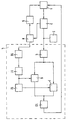
- Figure 1 shows the essential parts of the player in the form of a block diagram.
- the bits of the information to be stored in the optical storage disks are recorded by changing the reflection factor within the individual tracks.
- the respective track is illuminated by a laser diode and the reflected light is measured with a photo element.
- Laser diode and photo element are combined together with a lens and other control elements in a scanning head which has an optical axis, which in the construction of the player with the normal established at the scanning point the surface of the storage disks should coincide. Deviations between the optical axis and the normal lead to error rates in the later recognition of the stored information due to the impairment of the reflection conditions.
- the scanning head When reading out the information, the scanning head must be kept at a predetermined distance from the disk surface. It is guided in a radial direction from the inside to the outside of the storage disks. In order to maintain the correct distance, the scanning head is adjustable in the player.
- the actuator receives a control signal from an assembly called a focus servo. If the optical disk has a vertical stroke - this means that the distance between the disk surface and a permanently mounted scanning head would change periodically - then the focus servo supplies an AC voltage, the frequency of which corresponds to the speed.
- the inventor has now found that the high-frequency output voltage of the scanning head has a weak modulation when reading a disk with vertical impact, the frequency of which corresponds to the speed.
- This modulation is amplified if there is a misalignment between the optical axis of the scanning head and the normal to the surface of the storage disk at the scanning point.
- This modulation depends on the size of the misalignment.
- a minimum of the modulation must be set to correct the misalignment when adjusting the scanning head. To facilitate the adjustment, one works with a storage disk with a standardized vertical disk stroke when adjusting the readhead position.
- the block diagram now shows the essential modules required for correcting the misalignment.
- the correction can be carried out manually or automatically using controlled actuators respectively.
- the correction values of the control signals for the actuators are then written into suitable memories and are therefore available for the operating time of the playback device with this scanning head.
- the memory values must be reset after a repair on the readhead.
- the scanning head 1 supplies an output signal which is modulated at high frequency with the information read out, which is amplified by a preamplifier 2 and further processed in the data decoder 3.
- the output signal of the preamplifier 2 is further amplified in a measuring stage 4 in an amplifier 5, which can show a low-pass behavior, and then fed as an input signal to two synchronous demodulators 6, 7 connected in parallel.
- the preamplifier 2 has a second signal output to which the focus servo 8 is connected.
- This focus servo 8 delivers a signal with which the scanning head is kept at a constant distance from the disk surface by means of the focus actuator 9. In the case of a storage disk with a vertical disk blow, the signal is superimposed on the AC voltage already mentioned.
- This AC voltage is fed via a low-pass filter 10 and a limiter amplifier 11 directly to the control input of the first synchronous demodulator 6 and to the control input of the second synchronous demodulator 7 via a 90 ° phase shifter 12.
- the output voltages of the two synchronous demodulators now correspond to two components of the misalignment which are offset by 90 ° from one another.
- an evaluation circuit 13 can be used to perform two pivoting movements offset by 90 ° control in the bearing of the scanning head so that both components are at a minimum. These pivoting movements can, for. B. by 90 ° offset piezo elements in the bearing of the lens. If the correction value, ie the control voltages for the piezo elements, is stored, then measuring stage 4 can be set up as a separate part for the setting of the micro elements.
- the playback device must be equipped with an externally accessible tap for the RF-modulated output signal of the preamplifier and for the control signal for the focus actuator.
- the two output voltages can be displayed on a screen, where the minimization can be followed optically.
- the correction is expediently carried out in an iterative way, the direction of action of an adjustment made being checked.
- pivoting movements can, for. B. can also be caused by 90 ° offset piezo elements in the bearing of the drive motor.
- One of the piezo elements is expediently arranged in one plane with the scanning head.
Description
Gegenstand des Schutzrechts ist ein Verfahren zur Korrektur eines Fehlwinkels zwischen der optischen Achse des Abtastkopfes in einem Abspielgerät für optische Speicherplatten und der Normalen zur Oberfläche der Speicherplatte im Abtastpunkt.The object of the property right is a method for correcting a misalignment between the optical axis of the scanning head in a playback device for optical storage disks and the normal to the surface of the storage disk at the scanning point.
Aus der WO 92/04712, welche Stand der Technik gemäß Art. 54(3) EPÜ darstellt, ist ein Verfahren zum Messen oder Regeln des Radial-und Tangentialwinkels eines Lichtstrahls bekannt, bei dem der Tangentialwinkel und der Radialwinkel eines zum Lesen der Daten auf einen rotierenden Aufzeichnungsträger gerichteten Lichtstrahls gemessen oder auf einen Sollwert geregelt werden kann, wobei der Lichtstrahl vom Aufzeichnungsträger auf einen Fotodetektor reflektiert wird, dessen Ausgangssignal das Datensignal darstellt. Dieses Datensignal wird in einem Amplitudendemodulator demoduliert. Aus der Amplitude C und der Phasenlage ϕ des demodulierten Datensignals werden das Regelsignal UR = C·sinϕ·cosα für den Radialwinkel und das Regelsignal UT = -C cosϕ sinα für den Tangentialwinkel erzeugt. Die Werte von C und ϕ werden durch Messungen ermittelt. In einem Mikroprozessor werden aus dem demodulierten Datensignal die Regelsignale UR und UT berechnet. Die Regelsignale werden auf Regler gegeben, die zum Regeln des Tangentialwinkels und des Radialwinkels auf einen Sollwert dienen.From WO 92/04712, which represents prior art according to Art. 54 (3) EPC, a method for measuring or regulating the radial and tangential angle of a light beam is known, in which the tangential angle and the radial angle are used to read the data a rotating recording medium directed light beam can be measured or regulated to a target value, the light beam being reflected by the recording medium onto a photodetector, the output signal of which represents the data signal. This data signal is demodulated in an amplitude demodulator. The control signal UR = C · sinϕ · cosα for the radial angle and the control signal UT = -C cosϕ sinα for the tangential angle are generated from the amplitude C and the phase position ϕ of the demodulated data signal. The values of C and ϕ are determined by measurements. The control signals UR and UT are calculated in a microprocessor from the demodulated data signal. The control signals are sent to controllers that are used to control the tangential angle and the radial angle to a setpoint.
Aus der EP-0 313 818 A2 ist ein Gerät zum Lesen optischer Informationen bekannt, bei dem ein Abtaststrahl, der zum Bestrahlen einer Plattenoberfläche Verwendung findet, gewobbelt wird und bei dem eine Frequenz- und eine Amplitudenkomponente, die sich aus dieser Wobbelung ergeben, aus dem Ausgangssignal eines Lichtdetektors ermittelt werden. Die durch die Frequenz- und die Amplitudenkomponente zur Verfügung gestellte Information kann dazu benutzt werden, die Einflüsse von Plattenkrümmung und Plattenschlag zu kompensieren. Zum Wobbeln ist ein eigener Oszillator notwendig.From EP-0 313 818 A2 a device for reading optical information is known, in which a scanning beam, which is used for irradiating a plate surface, is wobbled and in which a frequency and an amplitude component resulting from this wobble result the output signal of a light detector can be determined. The information provided by the frequency and the amplitude component can be used for this to compensate for the influences of plate curvature and plate impact. A separate oscillator is required for wobbling.
Eine Korrektur des Fehlwinkels setzt die Lösung der Aufgabe voraus, ein Steuersignal verfügbar zu haben, dessen Größe eindeutig vom Fehlwinkel abhängt.Correcting the misalignment requires the solution to the problem of having a control signal available, the size of which clearly depends on the misalignment.
Die Erfindung, die auch diese Aufgabe löst, ist durch die Merkmale des Anspruchs 1 beziehungsweise des Anspruchs 5 gekennzeichnet.The invention, which also solves this problem, is characterized by the features of
Die Erfindung läßt sich mit Hilfe eines Abspielgerätes verwirklichen, daß durch die Merkmale des Anspruchs 2 beziehungsweise des Anspruchs 6 gekennzeichnet ist.The invention can be implemented with the aid of a player that is characterized by the features of claim 2 and
Die erfindungsgemäßen Verfahren mit den Merkmalen der unabhängigen Ansprüche 1 und 5 haben den Vorteil, daß durch Verschwenken des Abtastkopfes beziehungsweise des Antriebsmotors gezielt das Minimum der niederfrequenten Modulation und damit eine optimale Fehlwinkelkorrektur eingestellt wird, ohne daß der Abtaststrahl gewobbelt werden müßte oder die Fehlwinkel explizit zu berechnen wären. Die Korrektur eines Fehlwinkels ist daher auf einfache und wenig aufwendige Weise möglich.The method according to the invention with the features of
Durch die in den unabhängigen Ansprüchen 2 und 6 angegebenen erfindungsgemäßen Abspielgeräte für optische Speicherplatten sind vorteilhafte Realisierungen der in den Ansprüchen 1 beziehungsweise 5 angegebenen Verfahren möglich. Besonders vorteilhaft ist die Verwendung von Synchron-Demodulatoren, mit denen die Amplitude der Hüllkurve definiert zu vorgegebenen, für das Ausmaß der Modulation charakteristischen Zeiten erfaßt werden kann.The inventive playback devices for optical storage disks specified in
Durch die in den Unteransprüchen aufgeführten Maßnahmen sind vorteilhafte Weiterbildungen und Verbesserungen der in den unabhängigen Ansprüchen 2 und 6 angegebenen Abspielgeräten möglich. Besonders vorteilhaft ist die Verwendung zweier Synchron-Demodulatoren gemäß den Ansprüchen 3 und 7, deren Steuereingänge über einen 90°-Phasenschieber miteinander verbunden sind, wodurch beide Fehlwinkelkomponenten zur Fehlwinkelkorrektur berücksichtigt werden.The measures listed in the subclaims permit advantageous developments and improvements of the playback devices specified in
Figur 1 zeigt die hier wesentlichen Teile des Abspielgerätes in Form eines Blockschaltbildes.Figure 1 shows the essential parts of the player in the form of a block diagram.
Vor dessen Erläuterung wird zum besseren Verständnis vorausgeschickt, daß die Bits der zu speichernden Informationen in den optischen Speicherplatten durch eine Veränderung des Reflexionfaktors innerhalb der einzelnen Spuren aufgezeichnet werden. Bei Auslesen der Informationen wird die jeweilige Spur von einer Laserdiode beleuchtet und das reflektierte Licht mit einem Fotoelement gemessen. Laserdiode und Fotoelement sind zusammen mit einem Objektiv und weiteren der Regelung dienenden Elementen in einem Abtastkopf zusammengefaßt, der eine optische Achse besitzt, die bei dem Aufbau des Abspielgerätes mit der im Abtastpunkt errichteten Normalen auf der Oberfläche der Speicherplatten zusammenfallen soll. Abweichungen zwischen der optischen Achse und der Normalen führen wegen der Beeinträchtigung der Reflektionsverhältnisse zu Fehlerraten bei der späteren Erkennung der gespeicherten Informationen.Before it is explained, it is preceded for better understanding that the bits of the information to be stored in the optical storage disks are recorded by changing the reflection factor within the individual tracks. When the information is read out, the respective track is illuminated by a laser diode and the reflected light is measured with a photo element. Laser diode and photo element are combined together with a lens and other control elements in a scanning head which has an optical axis, which in the construction of the player with the normal established at the scanning point the surface of the storage disks should coincide. Deviations between the optical axis and the normal lead to error rates in the later recognition of the stored information due to the impairment of the reflection conditions.
Bei dem Auslesen der Informationen muß der Abtastkopf in einem vorgegebenen Abstand zur Plattenoberfläche gehalten werden. Er wird dabei in radialer Richtung über die Speicherplatten von innen nach außen geführt. Zur Einhaltung des richtigen Abstands ist der Abtastkopf im Abspielgerät verstellbar gelagert. Das Stellglied erhält ein Steuersignal von einer als Fokusservo bezeichneten Baugruppe. Hat die optische Speicherplatte einen vertikalen Schlag - das bedeutet, daß sich der Abstand zwischen der Plattenoberfläche und einem fest montierten Abtastkopf periodisch ändern würde - dann liefert der Fokusservo eine Wechselspannung, deren Frequenz der Drehzahl entspricht.When reading out the information, the scanning head must be kept at a predetermined distance from the disk surface. It is guided in a radial direction from the inside to the outside of the storage disks. In order to maintain the correct distance, the scanning head is adjustable in the player. The actuator receives a control signal from an assembly called a focus servo. If the optical disk has a vertical stroke - this means that the distance between the disk surface and a permanently mounted scanning head would change periodically - then the focus servo supplies an AC voltage, the frequency of which corresponds to the speed.
Der Erfinder hat nun festgestellt, daß auch die hochfrequente Ausgangsspannung des Abtastkopfes beim Lesen einer Speicherplatte mit vertikalem Schlag eine schwache Modulation aufweist, deren Frequenz der Drehzahl entspricht. Diese Modulation wird verstärkt, wenn zwischen der optischen Achse des Abtastkopfes und der Normalen der Oberfläche der Speicherplatte im Abtastpunkt ein Fehlwinkel besteht. Diese Modulation ist also abhängig von der Größe des Fehlwinkels. Dies führte den Erfinder zu der Lehre, daß man zur Korrektur des Fehlwinkels bei der Justage des Abtastkopfes ein Minimum der Modulation einzustellen hat. Zur Erleichterung der Justage arbeitet man bei der Einstellung der Abtastkopf-Stellung mit einer Speicherplatte mit einem genormten vertikalen Plattenschlag.The inventor has now found that the high-frequency output voltage of the scanning head has a weak modulation when reading a disk with vertical impact, the frequency of which corresponds to the speed. This modulation is amplified if there is a misalignment between the optical axis of the scanning head and the normal to the surface of the storage disk at the scanning point. This modulation depends on the size of the misalignment. This led the inventor to the teaching that a minimum of the modulation must be set to correct the misalignment when adjusting the scanning head. To facilitate the adjustment, one works with a storage disk with a standardized vertical disk stroke when adjusting the readhead position.
Das Blockschaltbild gibt nun die wesentlichen, für die Korrektur des Fehlwinkels erforderlichen Baugruppen wieder. Die Korrektur kann dabei manuell durchgeführt werden oder mittels gesteuerten Stellgliedern automatisch erfolgen. Die Korrekturwerte der Steuersignale für die Stellglieder werden dann in geeignete Speicher eingeschrieben und sind dadurch für die Betriebszeit des Abspielgerätes mit eben diesem Abtastkopf verfügbar. Nach einer Reparatur am Abtastkopf müssen die Speicherwerte neu eingestellt werden.The block diagram now shows the essential modules required for correcting the misalignment. The correction can be carried out manually or automatically using controlled actuators respectively. The correction values of the control signals for the actuators are then written into suitable memories and are therefore available for the operating time of the playback device with this scanning head. The memory values must be reset after a repair on the readhead.
Der Abtastkopf 1 liefert ein mit den ausgelesenen Informationen hochfrequent moduliertes Ausgangssignal, das von einem Vorverstärker 2 verstärkt wird und im Datendecoder 3 weiterverarbeitet wird.The
Das Ausgangssignal des Vorverstärkers 2 wird ferner in einer Meßstufe 4 erneut in einem Verstärker 5, der ein Tiefpaßverhalten zeigen kann, verstärkt und dann als Eingangssignal zwei parallelgeschalteten Synchron-Demodulatoren 6, 7 zugeführt.The output signal of the preamplifier 2 is further amplified in a measuring stage 4 in an
Der Vorverstärker 2 besitzt einen zweiten Signalausgang, an den der Fokusservo 8 angeschlossen ist. Dieser Fokusservo 8 liefert ein Signal, mit dem der Abtastkopf mittels des Fokusaktuators 9 auf gleichbleibenden Abstand zur Plattenoberfläche gehalten wird. Bei einer Speicherplatte mit einem vertikalen Plattenschlag ist dem Signal die bereits erwähnte Wechselspannung überlagert.The preamplifier 2 has a second signal output to which the
Diese Wechselspannung wird über einen Tiefpaß 10 und einem Begrenzerverstärker 11 dem Steuereingang des ersten Synchron-Demodulators 6 direkt und dem Steuereingang des zweiten Synchron-Demodulators 7 über einen 90°-Phasenschieber 12 zugeführt.This AC voltage is fed via a low-
Die Ausgangsspannungen der beiden Synchron-Demodulatoren entsprechen nun zwei um 90° gegeneinander versetzten Komponenten des Fehlwinkels. Mit beiden Ausgangsspannungen lassen sich mittels einer Auswertschaltung 13 zwei um 90° gegeneinander versetzten Schwenkbewegungen im Lager des Abtastkopfes derart steuern, daß beide Komponenten zu einem Minimum werden. Diese Schwenkbewegungen können z. B. durch um 90° gegeneinander versetzte Piezoelemente im Lager des Objektivs bewirkt werden. Sieht man eine Speicherung des Korrekturwertes, d. h. der Steuerspannungen für die Piezoelemente, vor, so kann für die Einstellung der Microelemente die Meßstufe 4 als separater Teil aufgebaut werden. Dazu ist das Abspielgerät mit einem von außen zugänglichen Abgriff für das HF-modulierte Ausgangssignal des Vorverstärkers und für das Steuersignal für den Fokusaktuator auszurüsten.The output voltages of the two synchronous demodulators now correspond to two components of the misalignment which are offset by 90 ° from one another. With two output voltages, an
Bei einer manuellen Verschwenkung des Abtastkopfes können die beiden Ausgangsspannungen auf einem Bildschirm dargestellt werden, wo sich die Minimisierung optisch verfolgen läßt. Die Korrektur wird dabei zweckmäßiger Weise auf einem iterativen Weg erfolgen, wobei die Wirkungsrichtung einer vorgenommenen Verstellung kontrolliert wird.When the scanning head is pivoted manually, the two output voltages can be displayed on a screen, where the minimization can be followed optically. The correction is expediently carried out in an iterative way, the direction of action of an adjustment made being checked.
Diese erwähnten Schwenkbewegungen können z. B. auch durch um 90° gegeneinander versetzte Piezoelemente im Lager des Antriebsmotors bewirkt werden. Zweckmäßigerweise wird eines der Piezoelemente in einer Ebene mit dem Abtastkopf angeordnet.These mentioned pivoting movements can, for. B. can also be caused by 90 ° offset piezo elements in the bearing of the drive motor. One of the piezo elements is expediently arranged in one plane with the scanning head.
Claims (8)
- Method for the correction of an error angle between the optical axis of an adjustably mounted scanning head (1) in a playing device for optical storage disks and the normal to the surface of the storage disk at the scanning point, characterized in that the minimum of the low-frequency modulation, caused by vertical run-out of the optical storage disk corresponding to the rotational speed of the optical storage disk, of the output voltage from the scanning head (1) is set by pivoting the scanning head (1).
- Playing device for optical storage disks, having an adjustably mounted scanning head (1) which comprises a lens, a laser diode and a photo element which supplies a high-frequency output signal which is decoded in the data decoder (3), as well as having a focus actuator (9) which is controlled by a focus servo (8) and with which the scanning head (1) is guided at a predefined distance from the disk surface, characterized in that at least one synchronous demodulator (6) is connected downstream of the scanning head (1), and in that the output signal from the focus servo (8) is fed via a low-pass filter (10) to the control input of the synchronous demodulator (6), and the output of the synchronous demodulator is connected to an evaluation unit (13) which controls pivoting movements of the scanning head (1) in such a way that the output signal from the synchronous demodulator (6) becomes a minimum.
- Playing device according to Claim 2, characterized in that two synchronous demodulators (6, 7) are connected in parallel downstream of the scanning head (1), and in that the output signal from the focus servo (8) is fed directly via a low-pass filter (10) to the control input of one synchronous demodulator (6) and via a 90° phase shifter (12) to the control input of the other synchronous demodulator (7), and in that the ouputs of the two synchronous demodulators are connected to the evaluation unit (13).
- Playing device according to Claim 3, characterized in that the mounting of the lens in the scanning head (1) comprises piezoelectric elements which are arranged at 90° to each other and whose control inputs are connected to the evaluation unit (13).
- Method for the correction of an error angle between the optical axis of a scanning head (1) in a playing device for optical storage disks and the normal to the surface of the storage disk at the scanning point, characterized in that the motor of the playing device is pivotably mounted and the minimum of the low-frequency modulation, caused by vertical run-out of the storage disk, of the output voltage from the scanning head (1) is set by pivoting the motor axis.
- Playing device for optical storage disks, having a drive motor, a scanning head (1) which comprises a lens, a laser diode and a photo element which supplies a high-frequency output signal which is decoded in the data decoder (3), as well as having a focus actuator (9) which is controlled by a focus servo (8) and with which the scanning head (1) is guided at a predefined distance from the disk surface, characterized in that at least one synchronous demodulator (6) is connected downstream of the scanning head (1), and the output signal from the focus servo (8) is fed via a low-pass filter (10) to the control input of the synchronous demodulator (6), and in that the output signal from the synchronous demodulator (6) controls pivoting movements in the mounting of the drive motor in such a way that the output signal from the synchronous demodulator (6) becomes a minimum.
- Playing device according to Claim 6, characterized in that two synchronous demodulators (6, 7) are connected in parallel downstream of the scanning head (1), and in that the output signal from the focus servo (8) is fed directly via a low-pass filter (10) to the control input of one synchronous demodulator (6) and via a 90° phase shifter (12) to the control input of the other synchronous demodulator (7), and in that the outputs of the two synchronous demodulators (6, 7) control, via an evaluation unit (13), two actuators arranged offset by 90° in the mounting of the drive motor.
- Playing device according to Claim 7, characterized in that one actuating element is located in one plane with the scanning head (1).
Applications Claiming Priority (4)
| Application Number | Priority Date | Filing Date | Title |
|---|---|---|---|
| DE4103506 | 1991-02-06 | ||
| DE4103506 | 1991-02-06 | ||
| DE19914103949 DE4103949A1 (en) | 1991-02-09 | 1991-02-09 | Correcting sensing head angle error in optical playback device |
| DE4103949 | 1991-02-09 |
Publications (3)
| Publication Number | Publication Date |
|---|---|
| EP0498246A2 EP0498246A2 (en) | 1992-08-12 |
| EP0498246A3 EP0498246A3 (en) | 1993-03-03 |
| EP0498246B1 true EP0498246B1 (en) | 1997-01-02 |
Family
ID=25900792
Family Applications (1)
| Application Number | Title | Priority Date | Filing Date |
|---|---|---|---|
| EP92101241A Expired - Lifetime EP0498246B1 (en) | 1991-02-06 | 1992-01-27 | Method for the correction of an error-angle |
Country Status (4)
| Country | Link |
|---|---|
| EP (1) | EP0498246B1 (en) |
| JP (1) | JPH04315824A (en) |
| DE (1) | DE59207786D1 (en) |
| ES (1) | ES2095965T3 (en) |
Families Citing this family (2)
| Publication number | Priority date | Publication date | Assignee | Title |
|---|---|---|---|---|
| US6904177B2 (en) * | 2001-03-13 | 2005-06-07 | Canon Kabushiki Kaisha | Filter processing apparatus |
| JP3995658B2 (en) * | 2004-02-12 | 2007-10-24 | 三洋電機株式会社 | Information recording / reproducing device |
Family Cites Families (4)
| Publication number | Priority date | Publication date | Assignee | Title |
|---|---|---|---|---|
| JPS5911543A (en) * | 1982-07-10 | 1984-01-21 | Sony Corp | Optical disc reproducer |
| JPS60143448A (en) * | 1983-12-29 | 1985-07-29 | Sony Corp | Skew error detecting circuit |
| JP2911449B2 (en) * | 1987-10-29 | 1999-06-23 | パイオニア株式会社 | Optical information reader |
| JP2572842B2 (en) * | 1989-05-10 | 1997-01-16 | パイオニア株式会社 | Apparatus for detecting crosstalk in optical read signal |
-
1992
- 1992-01-27 DE DE59207786T patent/DE59207786D1/en not_active Expired - Fee Related
- 1992-01-27 ES ES92101241T patent/ES2095965T3/en not_active Expired - Lifetime
- 1992-01-27 EP EP92101241A patent/EP0498246B1/en not_active Expired - Lifetime
- 1992-02-04 JP JP4018836A patent/JPH04315824A/en active Pending
Non-Patent Citations (1)
| Title |
|---|
| WO 92/04712 * |
Also Published As
| Publication number | Publication date |
|---|---|
| DE59207786D1 (en) | 1997-02-13 |
| JPH04315824A (en) | 1992-11-06 |
| EP0498246A3 (en) | 1993-03-03 |
| ES2095965T3 (en) | 1997-03-01 |
| EP0498246A2 (en) | 1992-08-12 |
Similar Documents
| Publication | Publication Date | Title |
|---|---|---|
| DE3346114C2 (en) | Optical disk device | |
| DE2935250C2 (en) | Tracking control device for the scanning light beam of an optical reading device | |
| DE3545996C2 (en) | ||
| DE3015474C2 (en) | Arrangement for controlling the setting of a reading light beam | |
| DE69833713T2 (en) | Position control device for optical read head | |
| DE3409588C2 (en) | Servo system for tracking and / or focusing in a data reader | |
| DE3618720A1 (en) | METHOD AND DEVICE FOR TRACKING AT IMAGE DISKS | |
| EP0313744A1 (en) | Focusing method for an optical reading device | |
| DE19515206A1 (en) | Method and apparatus for focusing control | |
| DE3730555C2 (en) | ||
| DE3831923A1 (en) | OPTICAL DEVICE FOR FOCUSING A LIGHT BEAM ON AN OBJECT FOR DATA RECORDING | |
| DE3501609C2 (en) | ||
| EP0498246B1 (en) | Method for the correction of an error-angle | |
| EP0249653B1 (en) | Reading device for the optical scanning of information recorded on a moving disc-shaped carrier | |
| DE60309542T2 (en) | Method and apparatus for correcting spherical aberration | |
| DE3502138A1 (en) | DEVICE FOR READING OPTICALLY RECORDED DATA | |
| EP0822542B1 (en) | Apparatus to read and/or write an optical record carrier | |
| EP0681290A1 (en) | Scanning device with adaptation | |
| EP0548120B1 (en) | Process and device for adjusting radial and tangential angles of light beams | |
| DE60316025T2 (en) | TILTING GUIDE FOR A DATA READING | |
| DE10162902B4 (en) | Optical disk device and method for adjusting the laser power of the optical disk device | |
| DE3151157C2 (en) | ||
| DE602004007118T2 (en) | METHOD AND DEVICE FOR MEASURING THE TILT OF AN OPTICAL PLATE. | |
| DE4103949A1 (en) | Correcting sensing head angle error in optical playback device | |
| DE3218265C2 (en) | Focusing device for the scanning light beam of an optical disc player |
Legal Events
| Date | Code | Title | Description |
|---|---|---|---|
| PUAI | Public reference made under article 153(3) epc to a published international application that has entered the european phase |
Free format text: ORIGINAL CODE: 0009012 |
|
| AK | Designated contracting states |
Kind code of ref document: A2 Designated state(s): DE ES FR IT |
|
| PUAL | Search report despatched |
Free format text: ORIGINAL CODE: 0009013 |
|
| AK | Designated contracting states |
Kind code of ref document: A3 Designated state(s): DE ES FR IT |
|
| 17P | Request for examination filed |
Effective date: 19930812 |
|
| 17Q | First examination report despatched |
Effective date: 19950814 |
|
| GRAG | Despatch of communication of intention to grant |
Free format text: ORIGINAL CODE: EPIDOS AGRA |
|
| GRAH | Despatch of communication of intention to grant a patent |
Free format text: ORIGINAL CODE: EPIDOS IGRA |
|
| GRAH | Despatch of communication of intention to grant a patent |
Free format text: ORIGINAL CODE: EPIDOS IGRA |
|
| GRAA | (expected) grant |
Free format text: ORIGINAL CODE: 0009210 |
|
| AK | Designated contracting states |
Kind code of ref document: B1 Designated state(s): DE ES FR IT |
|
| ET | Fr: translation filed | ||
| REF | Corresponds to: |
Ref document number: 59207786 Country of ref document: DE Date of ref document: 19970213 |
|
| REG | Reference to a national code |
Ref country code: ES Ref legal event code: FG2A Ref document number: 2095965 Country of ref document: ES Kind code of ref document: T3 |
|
| ITF | It: translation for a ep patent filed |
Owner name: 0414;07MIFSTUDIO JAUMANN |
|
| PLBE | No opposition filed within time limit |
Free format text: ORIGINAL CODE: 0009261 |
|
| STAA | Information on the status of an ep patent application or granted ep patent |
Free format text: STATUS: NO OPPOSITION FILED WITHIN TIME LIMIT |
|
| 26N | No opposition filed | ||
| PGFP | Annual fee paid to national office [announced via postgrant information from national office to epo] |
Ref country code: DE Payment date: 20070313 Year of fee payment: 16 |
|
| PGFP | Annual fee paid to national office [announced via postgrant information from national office to epo] |
Ref country code: ES Payment date: 20080125 Year of fee payment: 17 |
|
| PGFP | Annual fee paid to national office [announced via postgrant information from national office to epo] |
Ref country code: IT Payment date: 20080124 Year of fee payment: 17 |
|
| PGFP | Annual fee paid to national office [announced via postgrant information from national office to epo] |
Ref country code: FR Payment date: 20080118 Year of fee payment: 17 |
|
| PG25 | Lapsed in a contracting state [announced via postgrant information from national office to epo] |
Ref country code: DE Free format text: LAPSE BECAUSE OF NON-PAYMENT OF DUE FEES Effective date: 20080801 |
|
| REG | Reference to a national code |
Ref country code: FR Ref legal event code: ST Effective date: 20091030 |
|
| REG | Reference to a national code |
Ref country code: ES Ref legal event code: FD2A Effective date: 20090128 |
|
| PG25 | Lapsed in a contracting state [announced via postgrant information from national office to epo] |
Ref country code: FR Free format text: LAPSE BECAUSE OF NON-PAYMENT OF DUE FEES Effective date: 20090202 Ref country code: ES Free format text: LAPSE BECAUSE OF NON-PAYMENT OF DUE FEES Effective date: 20090128 |
|
| PG25 | Lapsed in a contracting state [announced via postgrant information from national office to epo] |
Ref country code: IT Free format text: LAPSE BECAUSE OF NON-PAYMENT OF DUE FEES Effective date: 20090127 |