EP0498143A1 - Active anti-dazzle device for the drivers of cars and other motor vehicles - Google Patents
Active anti-dazzle device for the drivers of cars and other motor vehicles Download PDFInfo
- Publication number
- EP0498143A1 EP0498143A1 EP91830038A EP91830038A EP0498143A1 EP 0498143 A1 EP0498143 A1 EP 0498143A1 EP 91830038 A EP91830038 A EP 91830038A EP 91830038 A EP91830038 A EP 91830038A EP 0498143 A1 EP0498143 A1 EP 0498143A1
- Authority
- EP
- European Patent Office
- Prior art keywords
- screen
- fitted
- electro
- signal
- sensitive screen
- Prior art date
- Legal status (The legal status is an assumption and is not a legal conclusion. Google has not performed a legal analysis and makes no representation as to the accuracy of the status listed.)
- Granted
Links
Images

Classifications
-
- A—HUMAN NECESSITIES
- A42—HEADWEAR
- A42B—HATS; HEAD COVERINGS
- A42B3/00—Helmets; Helmet covers ; Other protective head coverings
- A42B3/04—Parts, details or accessories of helmets
- A42B3/18—Face protection devices
- A42B3/22—Visors
- A42B3/226—Visors with sunscreens, e.g. tinted or dual visor
-
- A—HUMAN NECESSITIES
- A42—HEADWEAR
- A42B—HATS; HEAD COVERINGS
- A42B3/00—Helmets; Helmet covers ; Other protective head coverings
- A42B3/04—Parts, details or accessories of helmets
- A42B3/0406—Accessories for helmets
- A42B3/0433—Detecting, signalling or lighting devices
- A42B3/046—Means for detecting hazards or accidents
-
- B—PERFORMING OPERATIONS; TRANSPORTING
- B60—VEHICLES IN GENERAL
- B60J—WINDOWS, WINDSCREENS, NON-FIXED ROOFS, DOORS, OR SIMILAR DEVICES FOR VEHICLES; REMOVABLE EXTERNAL PROTECTIVE COVERINGS SPECIALLY ADAPTED FOR VEHICLES
- B60J3/00—Antiglare equipment associated with windows or windscreens; Sun visors for vehicles
- B60J3/04—Antiglare equipment associated with windows or windscreens; Sun visors for vehicles adjustable in transparency
Definitions
- This invention is an anti-dazzle device positioned in the field of vision of the driver of a car or other motor vehicle.
- Dazzle caused by the sun and headlights is very annoying for a driver (especially when meeting a column of cars coming in the opposite direction or during rain when visibility is reduced and reflections from the road surface are increased) and is also a very serious road traffic hazard which can lead to accidents; dazzle is particularly common on badly lit roads requiring the use of headlights on main beam which are not always dipped by drivers when meeting oncoming traffic.
- the aim of this invention is to eliminate the problems caused by dazzle through the use of an anti-dazzle device positioned in the driver's field of vision and which can be actuated, in real time, in the event of dazzle.
- the invention is cheap to make, practical, structurally simple and adaptable enough to be adjusted in accordance with the driver's height and needs, and the characteristics of the vehicle or accessory on which it is installed.
- the invention meets the aforementioned purposes in the form of a device having an electrical circuit consisting of an optic sensor which provides an output sensing signal proportional to the value of the luminosity intercepted in the sensor's field of reception at a specific angle.
- the sensor output signal is transmitted to a measuring/comparing circuit where it is compared with a preset threshold value; when the signal received exceeds the threshold value, the circuit transmits an output signal which actuates the power supply unit of an electro-sensitive screen.
- the electro-sensitive screen is designed to pass from a totally transparent state, when there is no actuating signal present, to a partially darkened or coloured state when the actuating signal is received; the screen will pass back to its transparent state again when the actuating signal is no longer transmitted.
- the anti-dazzle device for the drivers of cars and other motor vehicles covered by this invention consists of a complete electrical circuit 1 (see fig. 1) comprising an optic sensor 2 providing a sensing output signal (indicated by Ve) proportional to the value of luminosity intercepted in the sensor's field of reception at a specific angle (indicated by ⁇ ) of a beam of light 3 coming from oncoming headlights (on main beam) or the rising/setting sun.
- This optic sensor 2 transmits the signal Ve to a measuring/comparing circuit 4 where the signal Ve is compared with a preset threshold value (indicated by Vc in fig. 1); when the sensed signal Ve exceeds the preset threshold value Vc, the said measuring circuit 4 will output an actuating signal S to the power supply unit 4a (a simple diode, for example) of an electro-sensitive screen 5.
- This screen 5 is designed to pass from a state of total transparency, when there is no actuating signal S, to a partially darkened or coloured state when the actuating signal S is received; the screen 5 will pass back to its transparent state again when transmission of the actuating signal S ceases.
- the electro-sensitive screen 5, as shown here, could consist of a mainly horizontal glass strip, with a liquid crystal layer, positioned between the driver and the source of the beam of light 3.
- the optical sensor 2 could be positioned above the glass strip and could be fitted with a guide G to permit adjustment along the glass strip in accordance with the characteristics of the motor vehicle to which it is fitted.
- FIG. 2 A possible version of the invention is shown in figures 2 and 3 where the electro-sensitive screen 5 pivots at one of its sides on a support 6 fixed to the frame 7 of the motor vehicle 15 at the side the vehicle's windscreen 8 at the same position as the driver's field of vision; between the support 6 and the screen 5 there are means 9 for adjusting the screen 5 so that it can be moved along a minimum of two axes which are at right-angles to each other.
- the adjustment means 9 consist of a sleeve 16, fitted over a support 6, which rotates on its vertical axis and which can be fitted with a stop screw or other friction device (not shown here) to hold it in position; the sleeve 16 is joined to the screen 5 by a horizontal arm 17 (preferably telescopic) so as to permit horizontal and vertical adjustment of the screen to meet the driver's requirements.
- a variant of the screen 5 is shown in figure 4 attached to a crash-helmet 10 (preferably the full-face type) where a transparent visor 11 protecting the driver's eyes pivots at its edges on pivot buttons 18; in this case the electro-sensitive screen 5 consists of a pair of the strips 13, as already described, fixed to the visor 11. These strips 13 cover all the left part and part of the right part of the visor 11; the upper centre part of the visor 11 (i.e. on the vertical centre line of the driver's face) is fitted with the optic sensor 2.
- the optic sensor 2 and the screen 5 are connected to the measuring/comparing circuit 4 and to the diode 4a by electrical connections 21 consisting of sliding contacts at the pivot buttons 18 holding the edges of the visor 11.
- the circuit 4 and the diode 4a should preferably be housed in a pocket 12 made in the side padding of the crash-helmet 10 in order to facilitate removal for recharging and maintenance.
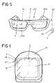
- FIG. 5 A further variant of the device is shown in figure 5.
- the device is mounted on a pair of spectacles 20 and consists of a pair of strips 14 (making up the screen 5) fitted to the frame 20a of the spectacles 20 over the lenses.
- the optic sensor 2 could be mounted on the bridge between the two lenses and could be connected to the measuring/comparing circuit (preferably not mounted on the spectacles) by electrical connections 22 (e.g. electrical wires) running along the side-pieces 20b of the spectacle frame.
- the operation of the device made to the design described above is simple (and is the same for all the variants described here).
- the screen is placed in front of the driver's eyes (during night driving). If a motor vehicle is illuminated by the main beam headlights of an oncoming vehicle, the beams of light are intercepted by the optic sensor which transmits a sensing signal to the measuring/comparing circuit. If the value of the sensing signal exceeds the threshold value, the circuit will transmit an actuating signal to the power supply unit for the screen so that the screen is partially darkened or coloured thus preventing dazzle in the driver's field of vision. When the light detected by the sensor falls below the preset threshold, the control circuit interrupts screen actuation and the screen returns to its original, totally transparent, condition.
- electro-sensitive screen 5 into the windscreen 8 of the motor vehicle or at least into that part of the windscreen which is directly in front of the driver. It would also be possible to hinge the screen on its support so that it could be rotated and moved out of the way when not in use.
- a further possible improvement would be to fit the circuit of the device with solar batteries.
Abstract
Description
- This invention is an anti-dazzle device positioned in the field of vision of the driver of a car or other motor vehicle.
- It is common when driving on roads or motorways to be dazzled by the rays of the rising or setting sun or, at night, to be dazzled by the headlights of oncoming vehicles.
- Dazzle caused by the sun and headlights, is very annoying for a driver (especially when meeting a column of cars coming in the opposite direction or during rain when visibility is reduced and reflections from the road surface are increased) and is also a very serious road traffic hazard which can lead to accidents; dazzle is particularly common on badly lit roads requiring the use of headlights on main beam which are not always dipped by drivers when meeting oncoming traffic.
- The aim of this invention is to eliminate the problems caused by dazzle through the use of an anti-dazzle device positioned in the driver's field of vision and which can be actuated, in real time, in the event of dazzle. The invention is cheap to make, practical, structurally simple and adaptable enough to be adjusted in accordance with the driver's height and needs, and the characteristics of the vehicle or accessory on which it is installed.
- The invention, described in the claims, meets the aforementioned purposes in the form of a device having an electrical circuit consisting of an optic sensor which provides an output sensing signal proportional to the value of the luminosity intercepted in the sensor's field of reception at a specific angle. The sensor output signal is transmitted to a measuring/comparing circuit where it is compared with a preset threshold value; when the signal received exceeds the threshold value, the circuit transmits an output signal which actuates the power supply unit of an electro-sensitive screen. The electro-sensitive screen is designed to pass from a totally transparent state, when there is no actuating signal present, to a partially darkened or coloured state when the actuating signal is received; the screen will pass back to its transparent state again when the actuating signal is no longer transmitted.
- The advantages and characteristics of this invention are described in greater detail below where reference is made to the enclosed drawings which represent one possible form of the invention and are not to be interpreted as being in any way restrictive. The drawings are as follows:
- figure 1 shows a block diagram of the device described in this invention;
- figures 2 and 3 show a side and front view, respectively, of the device in figure 1 fitted to a motor vehicle;
- figure 4 shows a front view of the device in figure 1 fitted to a full-face crash-helmet;
- figure 5 shows a front view of the device in figure 1 fitted to a pair of spectacles.
- With reference to the drawings, the anti-dazzle device for the drivers of cars and other motor vehicles covered by this invention consists of a complete electrical circuit 1 (see fig. 1) comprising an
optic sensor 2 providing a sensing output signal (indicated by Ve) proportional to the value of luminosity intercepted in the sensor's field of reception at a specific angle (indicated by α) of a beam oflight 3 coming from oncoming headlights (on main beam) or the rising/setting sun. - This
optic sensor 2 transmits the signal Ve to a measuring/comparingcircuit 4 where the signal Ve is compared with a preset threshold value (indicated by Vc in fig. 1); when the sensed signal Ve exceeds the preset threshold value Vc, the saidmeasuring circuit 4 will output an actuating signal S to thepower supply unit 4a (a simple diode, for example) of an electro-sensitive screen 5. Thisscreen 5 is designed to pass from a state of total transparency, when there is no actuating signal S, to a partially darkened or coloured state when the actuating signal S is received; thescreen 5 will pass back to its transparent state again when transmission of the actuating signal S ceases. - The electro-
sensitive screen 5, as shown here, could consist of a mainly horizontal glass strip, with a liquid crystal layer, positioned between the driver and the source of the beam oflight 3. Theoptical sensor 2 could be positioned above the glass strip and could be fitted with a guide G to permit adjustment along the glass strip in accordance with the characteristics of the motor vehicle to which it is fitted. - A possible version of the invention is shown in figures 2 and 3 where the electro-
sensitive screen 5 pivots at one of its sides on asupport 6 fixed to the frame 7 of themotor vehicle 15 at the side the vehicle'swindscreen 8 at the same position as the driver's field of vision; between thesupport 6 and thescreen 5 there are means 9 for adjusting thescreen 5 so that it can be moved along a minimum of two axes which are at right-angles to each other. The adjustment means 9 consist of asleeve 16, fitted over asupport 6, which rotates on its vertical axis and which can be fitted with a stop screw or other friction device (not shown here) to hold it in position; thesleeve 16 is joined to thescreen 5 by a horizontal arm 17 (preferably telescopic) so as to permit horizontal and vertical adjustment of the screen to meet the driver's requirements. - A variant of the
screen 5 is shown in figure 4 attached to a crash-helmet 10 (preferably the full-face type) where atransparent visor 11 protecting the driver's eyes pivots at its edges onpivot buttons 18; in this case the electro-sensitive screen 5 consists of a pair of the strips 13, as already described, fixed to thevisor 11. These strips 13 cover all the left part and part of the right part of thevisor 11; the upper centre part of the visor 11 (i.e. on the vertical centre line of the driver's face) is fitted with theoptic sensor 2. - The
optic sensor 2 and thescreen 5 are connected to the measuring/comparingcircuit 4 and to thediode 4a byelectrical connections 21 consisting of sliding contacts at thepivot buttons 18 holding the edges of thevisor 11. Thecircuit 4 and thediode 4a should preferably be housed in apocket 12 made in the side padding of the crash-helmet 10 in order to facilitate removal for recharging and maintenance. - A further variant of the device is shown in figure 5. In this case the device is mounted on a pair of
spectacles 20 and consists of a pair of strips 14 (making up the screen 5) fitted to theframe 20a of thespectacles 20 over the lenses. Theoptic sensor 2 could be mounted on the bridge between the two lenses and could be connected to the measuring/comparing circuit (preferably not mounted on the spectacles) by electrical connections 22 (e.g. electrical wires) running along the side-pieces 20b of the spectacle frame. - The operation of the device made to the design described above is simple (and is the same for all the variants described here). The screen is placed in front of the driver's eyes (during night driving). If a motor vehicle is illuminated by the main beam headlights of an oncoming vehicle, the beams of light are intercepted by the optic sensor which transmits a sensing signal to the measuring/comparing circuit. If the value of the sensing signal exceeds the threshold value, the circuit will transmit an actuating signal to the power supply unit for the screen so that the screen is partially darkened or coloured thus preventing dazzle in the driver's field of vision. When the light detected by the sensor falls below the preset threshold, the control circuit interrupts screen actuation and the screen returns to its original, totally transparent, condition.
- It would also be possible to incorporate the electro-
sensitive screen 5 into thewindscreen 8 of the motor vehicle or at least into that part of the windscreen which is directly in front of the driver. It would also be possible to hinge the screen on its support so that it could be rotated and moved out of the way when not in use. - he above description clearly shows that the device fully meets the purposes for which it was designed. It should also be noted that the time taken for the screen to darken is considerably less than the time taken for the human eye to react and adapt to dazzle. When the screen is in use the eye's pupils do not therefore have to work so hard and there is a consequent reduction in eye strain during night driving.
- A further possible improvement would be to fit the circuit of the device with solar batteries.
- This invention can be subject to numerous modifications and variations, all of which enter within the terms of the invention. All the details of this invention can be substituted by their technical equivalents.
Claims (8)
- Active anti-dazzle device for drivers of cars and other motor vehicles, wherein the device has an electrical circuit (1) consisting of an optical sensor (2) providing an output in the form of a sensing signal (Ve) proportional to the value of the luminosity intercepted in the said sensor's field of reception at a specific angle (α); the said sensor (2) is designed to transmit the signal (Ve) to a measuring/comparing circuit (4) where it is compared with a preset threshold value (Vc); when the signal (Ve) exceeds the preset threshold value (Vc), the said measuring circuit will output an actuating signal (S) to the power supply unit (4a) of an electro-sensitive screen (5) said screen being designed to pass from a state of total transparency, when there is no actuating signal (S), to a partially darkened or coloured state when the actuating signal (S) is transmitted and then back to its transparent state when the actuating signal (S) is no longer transmitted; the said electro-sensitive screen is positioned between the driver and the source of the oncoming beam of light (3).
- A device as in claim wherein the said electro-sensitive screen (5) consists of a liquid crystal glass strip.
- A device as in claim 1 wherein the said electro-sensitive screen (5) pivots, on one of its sides at least, on a support (6) fitted to the frame (7) at the side of the said motor vehicle's windscreen (8) at the same position as the driver's field of vision; there are means (9) for adjusting the said screen (5) located between the support (6) and the said screen so that the screen can be moved along a minimum of two axes which are at right-angles to each other; the said screen (5) is also fitted with an optic sensor (2).
- A device as in claim 1 wherein the said electro-sensitive screen (5) is incorporated into the said motor vehicle's windscreen (8) at least in that part of the windscreen directly in front of the driver.
- A device as in claim 1 fitted to a crash-helmet (10) having an eye-protection visor (11) whose edges pivot on buttons (18) fitted to the crash-helmet (10) wherein the said electro-sensitive screen (5) consists of at least one strip (13) fitted to at least one side of the said eye-protection visor (11); the said visor (11) also being fitted, at its upper centre part, with the said optic sensor (2); the said optic sensor (2) and the said screen (5) are electrically connected by means (21) to the said measuring/comparing circuit (4) housed inside a pocket (12) inside the said crash-helmet (10).
- A device as in claim 5 wherein the said connecting means (21) consist of sliding contacts fitted to at least one pivot button (18) of the said visor (11).
- A device as in claim 5 wherein the said crash-helmet (10) is fitted with at least two glass strips (13) in the area of the driver's eyes.
- A device as in claim 1 fitted to a pair of spectacles (20) wherein the said electro-sensitive screen (5) consists of a pair of strips (14) mounted on the frame (20a) of the said spectacles (20) covering the lenses; the said frame (20a) having a central bridge fitted with the said optic sensor (2) which, together with the said screen (5) is connected to the said measuring/comparing circuit (4) by connections located on the side-pieces (20b).
Priority Applications (5)
| Application Number | Priority Date | Filing Date | Title |
|---|---|---|---|
| EP91830038A EP0498143B1 (en) | 1991-02-08 | 1991-02-08 | Active anti-dazzle device for the drivers of cars and other motor vehicles |
| DE69122374T DE69122374T2 (en) | 1991-02-08 | 1991-02-08 | Active anti-glare device for drivers or other motor vehicles |
| DK91830038.5T DK0498143T3 (en) | 1991-02-08 | 1991-02-08 | |
| ES91830038T ES2094803T3 (en) | 1991-02-08 | 1991-02-08 | ANTI-GLAZE DEVICE LOCATED IN THE FIELD OF VISION OF THE DRIVER OF A CAR OR OTHER AUTOMOBILE VEHICLE. |
| US07/923,377 US5258607A (en) | 1991-02-08 | 1992-07-31 | Active anti-dazzle device for the drivers of cars and other motor vehicles having an electro-sensitive screen |
Applications Claiming Priority (1)
| Application Number | Priority Date | Filing Date | Title |
|---|---|---|---|
| EP91830038A EP0498143B1 (en) | 1991-02-08 | 1991-02-08 | Active anti-dazzle device for the drivers of cars and other motor vehicles |
Publications (2)
| Publication Number | Publication Date |
|---|---|
| EP0498143A1 true EP0498143A1 (en) | 1992-08-12 |
| EP0498143B1 EP0498143B1 (en) | 1996-09-25 |
Family
ID=8208926
Family Applications (1)
| Application Number | Title | Priority Date | Filing Date |
|---|---|---|---|
| EP91830038A Expired - Lifetime EP0498143B1 (en) | 1991-02-08 | 1991-02-08 | Active anti-dazzle device for the drivers of cars and other motor vehicles |
Country Status (5)
| Country | Link |
|---|---|
| US (1) | US5258607A (en) |
| EP (1) | EP0498143B1 (en) |
| DE (1) | DE69122374T2 (en) |
| DK (1) | DK0498143T3 (en) |
| ES (1) | ES2094803T3 (en) |
Cited By (15)
| Publication number | Priority date | Publication date | Assignee | Title |
|---|---|---|---|---|
| AT1495U1 (en) * | 1996-01-23 | 1997-06-25 | Prokesch Albin | GLARE PROTECTION FOR MOTOR VEHICLES |
| GB2309678A (en) * | 1996-01-29 | 1997-08-06 | Stephen John Payne | Screens for use by occupants of vehicles |
| WO1999062732A1 (en) * | 1998-05-29 | 1999-12-09 | Siemens Aktiengesellschaft | Antidazzle device for a motor vehicle and method for controlling the same |
| WO2001007276A1 (en) * | 1999-07-21 | 2001-02-01 | Lothar Ertl | Eye protecting device |
| WO2004019715A1 (en) * | 2002-08-26 | 2004-03-11 | Bayerische Motoren Werke Aktiengesellschaft | Self-tinting helmet visor |
| WO2013143998A2 (en) | 2012-03-26 | 2013-10-03 | Valeo Vision | Device for nighttime motor vehicle driving assistance |
| WO2013144003A1 (en) | 2012-03-26 | 2013-10-03 | Valeo Vision | Adaptive spectacles for motor vehicle drivers or passengers |
| DE202014101766U1 (en) | 2014-04-14 | 2014-05-22 | Gauzy Ltd. | Means for superimposing at least a first projected image on at least one second real image |
| FR3011095A1 (en) * | 2013-09-26 | 2015-03-27 | Valeo Vision | ADAPTIVE OPTICAL FILTER FOR GLASSES OF GLASSES |
| US9505290B2 (en) | 2012-03-26 | 2016-11-29 | Valeo Vision | Method and device for daytime motor vehicle driving assistance |
| US9897809B2 (en) | 2013-09-26 | 2018-02-20 | Valeo Vision | Data-display glasses comprising an anti-glare screen |
| US10073275B2 (en) | 2013-09-26 | 2018-09-11 | Valeo Vision | Anti-glare 3D glasses |
| US10195982B2 (en) | 2013-09-26 | 2019-02-05 | Valeo Vision | Driving assistance method and device |
| US10254545B2 (en) | 2013-09-26 | 2019-04-09 | Valeo Vision | Data-display glasses comprising an anti-glare screen |
| EP3616545A1 (en) * | 2018-08-29 | 2020-03-04 | Robert Bosch GmbH | Method and control device for the automatic shading of at least one partial area of a visor, visor which can be shaded, and helmet comprising a visor which can be shaded |
Families Citing this family (16)
| Publication number | Priority date | Publication date | Assignee | Title |
|---|---|---|---|---|
| US5305012A (en) * | 1992-04-15 | 1994-04-19 | Reveo, Inc. | Intelligent electro-optical system and method for automatic glare reduction |
| US5298732A (en) * | 1993-02-18 | 1994-03-29 | Emee, Inc. | Automatic visor for continuously repositioning a shading object to shade a designated location from a direct radiation source |
| DE4330817C1 (en) * | 1993-09-13 | 1994-12-01 | Optrel Ag | Method of controlling an antiglare device, and antiglare device for performing the method |
| DE19941125A1 (en) * | 1999-08-25 | 2001-03-08 | Uwe Peter Braun | Optical glare limiter |
| US6864473B2 (en) | 2000-12-07 | 2005-03-08 | The United States Of America As Represented By The United States National Aeronautics And Space Administration | Dynamic optical filtration |
| US7134707B2 (en) * | 2005-02-10 | 2006-11-14 | Motorola, Inc. | Selective light attenuation system |
| US8143563B2 (en) * | 2007-09-05 | 2012-03-27 | Craig Broude | Enhanced glare reduction |
| RU2444345C2 (en) * | 2010-01-11 | 2012-03-10 | Александр Сергеевич Студенцов | Antidazzle glasses for car drivers |
| US20140340770A1 (en) * | 2013-05-15 | 2014-11-20 | Thomas John Barniak, JR. | Lens assembly for the motor vehicle; a driver's aid for enhaned visibility while driving |
| FR3010941B1 (en) * | 2013-09-26 | 2017-01-13 | Valeo Vision | DEVICE AND METHOD FOR DRIVING ASSISTANCE |
| US9956854B2 (en) | 2016-07-12 | 2018-05-01 | Toyota Motor Engineering & Manufacturing North America, Inc. | Vehicle display screen safety and privacy system |
| US10262211B2 (en) | 2016-09-28 | 2019-04-16 | Wipro Limited | Windshield and a method for mitigating glare from a windshield of an automobile |
| US10939054B2 (en) | 2018-11-28 | 2021-03-02 | International Business Machines Corporation | Eliminating digital image artifacts caused by backlighting |
| US20210300428A1 (en) * | 2020-03-30 | 2021-09-30 | Toyota Research Institute, Inc. | Driver dazzle mitigation systems and methods |
| US20220169279A1 (en) * | 2020-12-02 | 2022-06-02 | Micron Technology, Inc. | Sunlight processing for autonomous vehicle control |
| CN113442691A (en) * | 2021-06-18 | 2021-09-28 | 科大讯飞股份有限公司 | Control method and device of intelligent vehicle membrane, storage medium and electronic equipment |
Citations (3)
| Publication number | Priority date | Publication date | Assignee | Title |
|---|---|---|---|---|
| US3961181A (en) * | 1975-02-18 | 1976-06-01 | Golden Eddie R | Eye-shading means for automotive vehicle operators |
| US4719462A (en) * | 1986-11-17 | 1988-01-12 | Hawkins David E | Radar detection helmet |
| US4848890A (en) * | 1987-08-27 | 1989-07-18 | Grumman Aerospace Corporation | Visor with point sun blocking |
Family Cites Families (3)
| Publication number | Priority date | Publication date | Assignee | Title |
|---|---|---|---|---|
| US1518956A (en) * | 1920-12-31 | 1924-12-09 | Albert B Beitman | Combined rear-view mirror and glare screen |
| BE755563A (en) * | 1969-09-02 | 1971-03-01 | Polaroid Corp | VARIABLE LIGHT FILTERING DEVICE |
| IT1117275B (en) * | 1977-02-25 | 1986-02-17 | Remo Bedini | AUTOMATIC METHOD AND DEVICE FOR THE ATTENTION OF THE DRIVING PHENOMENA IN REFLECTED LIGHT |
-
1991
- 1991-02-08 DK DK91830038.5T patent/DK0498143T3/da active
- 1991-02-08 DE DE69122374T patent/DE69122374T2/en not_active Expired - Fee Related
- 1991-02-08 EP EP91830038A patent/EP0498143B1/en not_active Expired - Lifetime
- 1991-02-08 ES ES91830038T patent/ES2094803T3/en not_active Expired - Lifetime
-
1992
- 1992-07-31 US US07/923,377 patent/US5258607A/en not_active Expired - Fee Related
Patent Citations (3)
| Publication number | Priority date | Publication date | Assignee | Title |
|---|---|---|---|---|
| US3961181A (en) * | 1975-02-18 | 1976-06-01 | Golden Eddie R | Eye-shading means for automotive vehicle operators |
| US4719462A (en) * | 1986-11-17 | 1988-01-12 | Hawkins David E | Radar detection helmet |
| US4848890A (en) * | 1987-08-27 | 1989-07-18 | Grumman Aerospace Corporation | Visor with point sun blocking |
Cited By (21)
| Publication number | Priority date | Publication date | Assignee | Title |
|---|---|---|---|---|
| AT1495U1 (en) * | 1996-01-23 | 1997-06-25 | Prokesch Albin | GLARE PROTECTION FOR MOTOR VEHICLES |
| GB2309678A (en) * | 1996-01-29 | 1997-08-06 | Stephen John Payne | Screens for use by occupants of vehicles |
| WO1999062732A1 (en) * | 1998-05-29 | 1999-12-09 | Siemens Aktiengesellschaft | Antidazzle device for a motor vehicle and method for controlling the same |
| WO2001007276A1 (en) * | 1999-07-21 | 2001-02-01 | Lothar Ertl | Eye protecting device |
| WO2004019715A1 (en) * | 2002-08-26 | 2004-03-11 | Bayerische Motoren Werke Aktiengesellschaft | Self-tinting helmet visor |
| US9079532B2 (en) | 2012-03-26 | 2015-07-14 | Valeo Vision | Device for nighttime motor vehicle driving assistance |
| US9505290B2 (en) | 2012-03-26 | 2016-11-29 | Valeo Vision | Method and device for daytime motor vehicle driving assistance |
| US9869886B2 (en) | 2012-03-26 | 2018-01-16 | Valeo Vision | Adaptive spectacles for motor vehicle drivers or passengers |
| US9688183B2 (en) | 2012-03-26 | 2017-06-27 | Valeo Vision | Device for nighttime motor vehicle driving assistance |
| WO2013144003A1 (en) | 2012-03-26 | 2013-10-03 | Valeo Vision | Adaptive spectacles for motor vehicle drivers or passengers |
| WO2013143998A2 (en) | 2012-03-26 | 2013-10-03 | Valeo Vision | Device for nighttime motor vehicle driving assistance |
| WO2015044354A1 (en) * | 2013-09-26 | 2015-04-02 | Valeo Vision | Adaptive optical filter for spectacle lenses |
| JP2016535289A (en) * | 2013-09-26 | 2016-11-10 | ヴァレオ ビジョンValeo Vision | Adaptive optical filter for eyeglass lenses |
| FR3011095A1 (en) * | 2013-09-26 | 2015-03-27 | Valeo Vision | ADAPTIVE OPTICAL FILTER FOR GLASSES OF GLASSES |
| US9897809B2 (en) | 2013-09-26 | 2018-02-20 | Valeo Vision | Data-display glasses comprising an anti-glare screen |
| US9915831B2 (en) | 2013-09-26 | 2018-03-13 | Valeo Vision | Adaptive optical filter for spectacle lenses |
| US10073275B2 (en) | 2013-09-26 | 2018-09-11 | Valeo Vision | Anti-glare 3D glasses |
| US10195982B2 (en) | 2013-09-26 | 2019-02-05 | Valeo Vision | Driving assistance method and device |
| US10254545B2 (en) | 2013-09-26 | 2019-04-09 | Valeo Vision | Data-display glasses comprising an anti-glare screen |
| DE202014101766U1 (en) | 2014-04-14 | 2014-05-22 | Gauzy Ltd. | Means for superimposing at least a first projected image on at least one second real image |
| EP3616545A1 (en) * | 2018-08-29 | 2020-03-04 | Robert Bosch GmbH | Method and control device for the automatic shading of at least one partial area of a visor, visor which can be shaded, and helmet comprising a visor which can be shaded |
Also Published As
| Publication number | Publication date |
|---|---|
| ES2094803T3 (en) | 1997-02-01 |
| EP0498143B1 (en) | 1996-09-25 |
| DE69122374T2 (en) | 1997-04-30 |
| DK0498143T3 (en) | 1997-03-03 |
| DE69122374D1 (en) | 1996-10-31 |
| US5258607A (en) | 1993-11-02 |
Similar Documents
| Publication | Publication Date | Title |
|---|---|---|
| US5258607A (en) | Active anti-dazzle device for the drivers of cars and other motor vehicles having an electro-sensitive screen | |
| US9869886B2 (en) | Adaptive spectacles for motor vehicle drivers or passengers | |
| US20090116098A1 (en) | Device for adjusting the tint of glass | |
| US5513892A (en) | Sun glare shield | |
| KR19990022655A (en) | Brightness Reduction Device and Method | |
| US5428409A (en) | Night driving glasses | |
| US4182552A (en) | Side view mirror employing prism for blind spot correction | |
| US6056397A (en) | Method and apparatus for reducing glare while driving | |
| US4828380A (en) | Anti-glare eyeglasses | |
| US4818011A (en) | Anti-glare visor system | |
| KR20150000477A (en) | Method and device for daytime motor vehicle driving assistance | |
| CN211844048U (en) | Automobile-used sunshading board system and vehicle | |
| CN1187252A (en) | Light indensity reduction apparatus and method of reduction | |
| KR20180096126A (en) | Shading plate for adjusting transmittance of light | |
| JPH08136883A (en) | Electronic sunglasses | |
| JPH04238724A (en) | Glare shield device | |
| US3695658A (en) | Glare shield | |
| CN2297742Y (en) | Automatic variable colour highlight protective goggles | |
| US3597052A (en) | Antiglare attachment for spectacles | |
| RU2082209C1 (en) | Antidazzle device | |
| US2757955A (en) | Glare shield for automobiles | |
| WO1987004396A1 (en) | Screening method of blinding lights for vehicles | |
| USRE30673E (en) | Side view mirror employing prism for blind spot correction | |
| JPH05203906A (en) | Antidazzling system | |
| RU92789U1 (en) | DRIVER EYE PROTECTION SYSTEM WHEN BLINDING HEADLIGHTS OF A BOARD VEHICLE |
Legal Events
| Date | Code | Title | Description |
|---|---|---|---|
| PUAI | Public reference made under article 153(3) epc to a published international application that has entered the european phase |
Free format text: ORIGINAL CODE: 0009012 |
|
| AK | Designated contracting states |
Kind code of ref document: A1 Designated state(s): BE CH DE DK ES FR GB IT LI NL |
|
| 17P | Request for examination filed |
Effective date: 19921008 |
|
| 17Q | First examination report despatched |
Effective date: 19940310 |
|
| GRAG | Despatch of communication of intention to grant |
Free format text: ORIGINAL CODE: EPIDOS AGRA |
|
| GRAH | Despatch of communication of intention to grant a patent |
Free format text: ORIGINAL CODE: EPIDOS IGRA |
|
| GRAH | Despatch of communication of intention to grant a patent |
Free format text: ORIGINAL CODE: EPIDOS IGRA |
|
| GRAA | (expected) grant |
Free format text: ORIGINAL CODE: 0009210 |
|
| AK | Designated contracting states |
Kind code of ref document: B1 Designated state(s): BE CH DE DK ES FR GB IT LI NL |
|
| REF | Corresponds to: |
Ref document number: 69122374 Country of ref document: DE Date of ref document: 19961031 |
|
| ITF | It: translation for a ep patent filed |
Owner name: STUDIO BREVETTI NAZ. ED ESTERI |
|
| REG | Reference to a national code |
Ref country code: CH Ref legal event code: NV Representative=s name: PATENTANWAELTE GEORG ROEMPLER UND ALDO ROEMPLER |
|
| REG | Reference to a national code |
Ref country code: ES Ref legal event code: FG2A Ref document number: 2094803 Country of ref document: ES Kind code of ref document: T3 |
|
| ET | Fr: translation filed | ||
| REG | Reference to a national code |
Ref country code: DK Ref legal event code: T3 |
|
| PGFP | Annual fee paid to national office [announced via postgrant information from national office to epo] |
Ref country code: FR Payment date: 19970722 Year of fee payment: 7 |
|
| PGFP | Annual fee paid to national office [announced via postgrant information from national office to epo] |
Ref country code: GB Payment date: 19970725 Year of fee payment: 7 |
|
| PGFP | Annual fee paid to national office [announced via postgrant information from national office to epo] |
Ref country code: BE Payment date: 19970730 Year of fee payment: 7 |
|
| PGFP | Annual fee paid to national office [announced via postgrant information from national office to epo] |
Ref country code: NL Payment date: 19970731 Year of fee payment: 7 Ref country code: ES Payment date: 19970731 Year of fee payment: 7 Ref country code: DE Payment date: 19970731 Year of fee payment: 7 |
|
| PLBE | No opposition filed within time limit |
Free format text: ORIGINAL CODE: 0009261 |
|
| STAA | Information on the status of an ep patent application or granted ep patent |
Free format text: STATUS: NO OPPOSITION FILED WITHIN TIME LIMIT |
|
| PGFP | Annual fee paid to national office [announced via postgrant information from national office to epo] |
Ref country code: DK Payment date: 19970812 Year of fee payment: 7 |
|
| PGFP | Annual fee paid to national office [announced via postgrant information from national office to epo] |
Ref country code: CH Payment date: 19970819 Year of fee payment: 7 |
|
| 26N | No opposition filed | ||
| PG25 | Lapsed in a contracting state [announced via postgrant information from national office to epo] |
Ref country code: GB Free format text: LAPSE BECAUSE OF NON-PAYMENT OF DUE FEES Effective date: 19980208 |
|
| PG25 | Lapsed in a contracting state [announced via postgrant information from national office to epo] |
Ref country code: ES Free format text: LAPSE BECAUSE OF NON-PAYMENT OF DUE FEES Effective date: 19980209 |
|
| PG25 | Lapsed in a contracting state [announced via postgrant information from national office to epo] |
Ref country code: LI Free format text: LAPSE BECAUSE OF NON-PAYMENT OF DUE FEES Effective date: 19980228 Ref country code: FR Free format text: THE PATENT HAS BEEN ANNULLED BY A DECISION OF A NATIONAL AUTHORITY Effective date: 19980228 Ref country code: CH Free format text: LAPSE BECAUSE OF NON-PAYMENT OF DUE FEES Effective date: 19980228 Ref country code: BE Free format text: LAPSE BECAUSE OF NON-PAYMENT OF DUE FEES Effective date: 19980228 |
|
| PG25 | Lapsed in a contracting state [announced via postgrant information from national office to epo] |
Ref country code: DK Free format text: LAPSE BECAUSE OF NON-PAYMENT OF DUE FEES Effective date: 19980302 |
|
| BERE | Be: lapsed |
Owner name: AGOSTINI GIORGIO Effective date: 19980228 Owner name: NOLI MARCO Effective date: 19980228 Owner name: AGOSTINI ALBERTO Effective date: 19980228 |
|
| PG25 | Lapsed in a contracting state [announced via postgrant information from national office to epo] |
Ref country code: NL Free format text: LAPSE BECAUSE OF NON-PAYMENT OF DUE FEES Effective date: 19980901 |
|
| GBPC | Gb: european patent ceased through non-payment of renewal fee |
Effective date: 19980208 |
|
| REG | Reference to a national code |
Ref country code: CH Ref legal event code: PL |
|
| NLV4 | Nl: lapsed or anulled due to non-payment of the annual fee |
Effective date: 19980901 |
|
| PG25 | Lapsed in a contracting state [announced via postgrant information from national office to epo] |
Ref country code: DE Free format text: LAPSE BECAUSE OF NON-PAYMENT OF DUE FEES Effective date: 19981103 |
|
| REG | Reference to a national code |
Ref country code: FR Ref legal event code: ST |
|
| REG | Reference to a national code |
Ref country code: DK Ref legal event code: EBP |
|
| REG | Reference to a national code |
Ref country code: ES Ref legal event code: FD2A Effective date: 20000403 |
|
| PG25 | Lapsed in a contracting state [announced via postgrant information from national office to epo] |
Ref country code: IT Free format text: LAPSE BECAUSE OF NON-PAYMENT OF DUE FEES;WARNING: LAPSES OF ITALIAN PATENTS WITH EFFECTIVE DATE BEFORE 2007 MAY HAVE OCCURRED AT ANY TIME BEFORE 2007. THE CORRECT EFFECTIVE DATE MAY BE DIFFERENT FROM THE ONE RECORDED. Effective date: 20050208 |