EP0497879B1 - Transmission of broadband signals - Google Patents
Transmission of broadband signals Download PDFInfo
- Publication number
- EP0497879B1 EP0497879B1 EP90916782A EP90916782A EP0497879B1 EP 0497879 B1 EP0497879 B1 EP 0497879B1 EP 90916782 A EP90916782 A EP 90916782A EP 90916782 A EP90916782 A EP 90916782A EP 0497879 B1 EP0497879 B1 EP 0497879B1
- Authority
- EP
- European Patent Office
- Prior art keywords
- cable
- electrical
- signal
- conductors
- broadband
- Prior art date
- Legal status (The legal status is an assumption and is not a legal conclusion. Google has not performed a legal analysis and makes no representation as to the accuracy of the status listed.)
- Expired - Lifetime
Links
Images

Classifications
-
- H—ELECTRICITY
- H04—ELECTRIC COMMUNICATION TECHNIQUE
- H04B—TRANSMISSION
- H04B3/00—Line transmission systems
-
- H—ELECTRICITY
- H04—ELECTRIC COMMUNICATION TECHNIQUE
- H04N—PICTORIAL COMMUNICATION, e.g. TELEVISION
- H04N7/00—Television systems
- H04N7/10—Adaptations for transmission by electrical cable
- H04N7/108—Adaptations for transmission by electrical cable the cable being constituted by a pair of wires
Definitions
- the present invention relates to a method and devices for transmission of broadband electrical signals, for example data and/or video, to a subscriber, particularly a subscriber who has a pre-installed telephone cable.
- the invention can avoid the need for installation of further drop cables (generally coaxial cables), dedicated to the new data or video service.
- any bandwidth greater than that for simple telephone operation (voice band, generally about 4 KHz alalogue amplitude modulated and 64 KHz digital) preferably greater than that for 2,3,4,5,10 or 20 combined public switched telephone signals is referred to as broadband, and includes but is not limited to data and video.
- RF, VHF, and UHF signals preferably of frequency greater than 20, more preferably greater than 30, especially greater than 40 KHz analogue (AM) or greater than 200,300 or 400 KHz digital.
- AM KHz analogue
- the invention may also be considered useful for signals having a bandwidth of at least 0.0001, 0.001 or 0.01 times that of NTSC format video.
- CATV cable television
- US patent no. 4054910 discloses a communications system which allows dosed circuit television pictures to be transmitted from conventional TV cameras to conventional monitors via an ordinary pair of wires, for example, telephone wires, lamp cord, BX cable etc. This is achieved by providing transmitter and receiver adaptors which include differential amplifiers and suitable frequency compensation networks which provide the necessary compensation with a minimum of adjustments while being insensitive to external fields and interferences. Additionally, US patent no. 4485400 discloses an apparatus and method for transmitting video data over telephone lines.
- a portable self-contained unit is provided at each end of a conventional telephone circuit, the transducers of the mouthpiece and earpiece of each telephone being respectively acoustically coupled to acoustic output and input electrical-to-sound and sound-to-electrical transducers of each self-contained unit, to enable two-way audio and video communication between the units.
- British patent no. 1272594 discloses a wired broadcasting system in which the connection between a programme exchange and a subscriber's terminal unit is made by means of a feeder cable comprising a twisted pair of wires for the programme signals from the exchange to the terminal unit and a pair of control wires for control signals from the terminal unit to the exchange. Each control wire is located in one of the interstices between the signal wires.
- the invention provides a method of transmitting a broadband electrical signal (ie. a signal having a barewidth greater than that for simple telephone operation such as data or video and particularly RF, VHF or UHF signals) to a subscriber by means of a telecommunications cable, preferably a telephone cable particularly a drop cable, preferably a preinstalled cable, characterised in that the telecommunications cable comprises at least one pair of electrical conductors surrounded by an electrical shield, which method comprises applying the broadband signal between (a) the shield and (b) at least provided in pairs, preferably twisted pairs, and the cable preferably is not of the coaxial type.
- a broadband electrical signal ie. a signal having a barewidth greater than that for simple telephone operation such as data or video and particularly RF, VHF or UHF signals
- the invention can, nonetheless, be used where this surplus capacity is not present. This can be done, for example, by transforming the telephone signal into a high frequency signal and multiplexing that signal with the new broadband signal, and transmitting the combined signal in the way defined above. The signals would then be separated at the subscriber's premises. An alternative would be to retain the telephone signal at voice band frequency and apply the broadband signal on top of it at higher frequency. Again, some means of separation would be provided at the subscriber's premises.
- the precise way in which the broadband signal is applied to the cable may depend on the type of cable, its length, the network architecture and the signal transmitted etc. For example, it may be applied between (a) the shield and (b) both of the conductors of the pair.
- the cable may comprise at least two pairs of electrical conductors surrounded by a an electrical shield, and the signal applied between (a) the shield and at least one (preferably both) of the conductors of one of the pairs and (b) at least one (preferably both) of the conductors of another of the pairs. That configuration where both conductors of the pairs referred to are employed is preferred at least for drop cables having six pairs (such as those used by the German Bundespost), and for the preferred network systems described below.
- one or more additional pairs can be dedicated to transmission of a voice band signal, such a signal being applied between the conductors of a pair in the usual way. If desired, substantially all of the unused pairs may be connected to the shield and if additional telephone service is later required one or more oof such pairs can be disconnected from the shield and used for telephone signals.
- a preferred broad-band network and a preferred telephone network with which it may be used.
- a distribution cable which may contain a few hundred pairs of conductors, runs generally along public roads etc, and branch joints are made at regular intervals at which drop wires or cables running to each subscriber are spliced into the distribution cable.
- branch joints may be environmentally sealed by an enclosure known as a splice case, for example a heat-shrinkable article such as that supplied by Raychem to the German Bundespost under the Trade Mark VASM.
- the present broadband signal is applied to the drop cable preferably at a position between the splice case at the distribution cable and the subscriber. It is preferably applied near the splice case such that the splice case and a further enclosure (which may also comprise a heat-shrinkable article) environmentally-sealing a splice to a cable applying the broadband signal may be contained within a single housing such as a pedestal or a manhole (which term includes a hand hole). In some cases, a cable applying the broadband signal may be spliced at the splice case between the distribution cable and the drop cable, and a single splice case may then be used.
- the cable introducing the broadband signal (which may comprise a coaxial cable) is preferably spliced to the drop cable (or to the distribution cable or to its drop splice) by a method that during splicing maintains conductivity along at least one pair of conductors of the drop telephone cable, since in this way telephone service to the subscriber need not be interrupted during introduction of the new broadband service. A preferred way in which this may be done will be described below.
- the broadband signal is preferably transmitted to the drop cable from an active network device that is only a short distance away, and that is preferably contained in the same pedestal, man-hole or other housing that contains the splice closures.
- That active device may comprise an amplifier and may comprise an electrical/optical convertor that generates the broadband electrical signal from an optical signal withdrawn from a waveguide such as an optical fibre.
- the active device may comprise means for adjusting the power of the broadband signal preferably according to an attenuation characteristic of the drop telephone cable. This ability to adjust the signal may be important since, in general, drop cables do not have the predetermined characteristics such as attenuation as a function of signal frequency or cable length that may be expected of a coaxial cable.
- Such an active device may be provided one for each subscriber, in which case optimum performance may be obtained for each subscriber in spite of the varying lengths of drop cables (generally less than 100m, preferably less than 50m) from the positions where the signal is introduced to each subscriber.
- the invention is particularly usefully used in conjunction on optical fibre distribution network that carries the broadband signal.
- That network may also carry the voice band telephone signal, the two different signals then being applied to the drop cable of an existing telephone network.
- the broadband and voice bands may be separated before application to the drop cable, and they may be separately applied as indicated above. Whilst installation of the new broadband system requires laying of the fibre cables generally along public rights of way, the cost and inconvenience of laying new drop cables into customers' premises is avoided.
- the optical fibre network may supply merely new services, such as data or video, and the existing telephone network continue to supply a telephone service.
- a single mode or multimode fibre bus runs from a telecommunications central office along a public right of way or other route adjacent many subscriber premises.
- the bus may carry multiplexed signals, allowing many or all of the subscribers to communicate independently.
- Subscriber interface units are provided regularly along the bus, a preferred number being 20-30 generally about 24 per bus.
- Each SIU is provided with one or more optical taps by means of which an optical signal is withdrawn from the bus.
- the taps are preferably non-invasive, and preferably comprise a means for bending the fibre and an optical coupler that may be applied to the bent portion of the fibre such that the optical signal is withdrawn through a buffer of the fibre at an intermediate position along its length.
- An elecrical/optical convertor is provided to convert the optical signal from the fibre into the broadband electrical signal that is applied to the drop cable. This tapping and detection is disclosed and claimed in US 4747652 (Raychem), the disclosure of which is incorporated herein by reference.
- the SIU may also provide power and it may have electronics that can identify, for example, packets of information received by means of an address code, and pass on only those intended for the subscriber or subscribers that it serves.
- Each SIU preferably serves 4-25, particularly about 8 subscribers, and the method of the invention therefore envisages transmission of one or more signals to a plurality of subscribers, with if desired, individual adjustments of signal power for each subscriber.
- an SIU be provided with means whereby a characteristic (especially power) of each signal it applies to respective drop cables be independently adjustable according to some characteristic (especially attenuation) of the respective drop cable.
- An SIU preferably has an enclosure especially of butt design to protect the tap or taps and any electronics etc from the environment.
- the entering and leaving optical fibre cables may be sealed to the enclosure by a heat-shrinkable article, or the enclosure itself may be provided by a heat-shrinkable article.
- This enclosure is preferably contained within the same pedestal, man-hole or other housing referred to above.
- the broadband signal may be applied to the telephone drop cable.
- An enclosure for use in making an electrical connection to a cable at a portion between the end of the cable, the cable comprising at least one pair of conductors surrounded by an electrical shield may comprise:
- the enclosure may optionally include:
- the enclosure or part of it is preferably of "wrap-around" design.
- the term "wrap-around” is well understood in the cables accessories art (reference may be made for example to GB 1155470), and as used herein it implies no particular shape nor flexibility, but rather the ability of installation around an elongate substrate (such as a cable) without access to an end thereof.
- the enclosure preferably has an inlet and outlet that are not permanently closed in cross-section, but instead are or may be opened out such that the cables may be laterally inserted therein.
- the enclosure may comprise two half-shells that are brought together around the cable.
- the half-shells may be hinged or otherwise fixed together to give the enclosure the configuration of a clam-shell.
- This wrap-around, halfshell or clam-shell design may be possessed by the entire enclosure or only part of it.
- the enclosure may comprise a substantially rectangular box, having a removable lid.
- Outlets and inlets may be provided at opposite edge faces (for an in-line design) or at a single edge face (for a butt design).
- the outlets/inlets may comprise extensions to the faces, or part of the outlets/inlets may be provided by the faces, and part by the lid, such that the closed cross-section of the outlets/inlets regain a closed cross-section when the lid is in place.
- Such an enclosure can be built around a cable without severing all of its conductors.
- the inlets/outlets preferably have contact means, such as mechanical contacts, preferably resiliently biased, and especially in the form of leaf-springs, which make contact with the cable shield.
- the enclosure may have an inlet and an outlet for the telephone cable, and a similar inlet for a coaxial cable carrying the broadband signal.
- the enclosure may therefore have some similarities to a conventional CATV splitter box. Its function will however be different, and some aspects of its structure will therefore be different. In particular its main inlet and outlet, whilst having contacts for an outer conductor, will not in general have a contact for a coaxial cable central conductor but will preferably have means for organizing and making connections to the pairs of conductors carried by a regular telephone cable.
- a method and corresponding enclosure for making an electrical connection to a cable comprising at least one pair of conductors surrounded by an electrical shield comprises:
- FIG. 1 shows a conventional way in which a telephone signal is transmitted to a telephone 1 or socket therefor at a subscriber's premises 2.
- a distribution cable 3 is spliced to a drop telephone cable 4, the splice being sealed by a splice case 5.
- a broadband coaxial cable 6 is also installed, having a drop coaxial cable 7 spliced at a passive splitter 8.
- the drop coaxial cable 7 also leads to the subscriber 2, and is terminated at a television or computer etc or a socket therefor. Where a broadband service has to be provided to a subscriber 1 a new line 7 has to be added which generally requires excavation since existing cable 4 is likely to be direct buried rather than ducted.
- FIG. 2 illustrates the invention.
- a broadband signal is applied to the drop cable 4 by means of broadband cable 10 at a position 11 between the subscriber 2 and splice case 5.
- the broadband signal transmitted in cable 10, which may comprise a coaxial cable, is preferably obtained from a device such as a subscriber interface unit (SIU) 12.
- SIU 12 may have many functions, especially the withdrawal of an optical signal from an optical fibre bus 13, and its conversion to an electrical signal of the desired power.
- the desired power of the electrical signal will depend on a characteristic of the drop cable 4 particularly on its attenuation between position 11 and the subscriber 2.
- the splice 5, the SIU 12 and an enclosure around a splice between cables 4 and 10 may all be sealed using heat-shrinkable articles and since they are preferably located close to one another they are preferably located in a single housing 15.
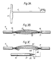
- Figures 3A, 3B and 3C illustrate a way in which cable 10 may be joined to drop cable 4.
- a portion of cable jacket 16 is removed from between the ends of cable 4, and a shorter length of cable shield 17 is removed, leaving exposed cable shield at each end. This reveals twisted pairs of conductors 18.
- Cable 10 is then electrically connected to cable 4 such that a broadband signal carried by cable 10 is applied between (a) the shield 17 and the conductors of one pair 6A and (b) the conductors of another pair 6B.
- Other pairs, for example 6C remain for transmission of a telephone signal.
- the cable supplying the broadband signal is a coaxial cable 10 comprising a central conductor 19, and outer conductor 20 and a jacket 21.
- connection made in figures 3A, 3B and 3C may be performed without disrupting the telephone service provided along twisted pair 6C. This may be done by building an enclosure around the drop cable 4 and, for example, plugging cable 10 into that enclosure. Such an enclosure may contain the various connections and any electronics necessary.
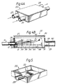
- the drop cable 4 may enter through inlet 23 and leave through outlet 24.
- the cable 10 supplying the broadband signal may enter through inlet 25.
- Figure 4B shows a partial section through an enclosure of the general type as that shown in figure 4A.
- the enclosure comprises a generally rectangular, hollow body 26 and lid 27.
- the outlet 24 makes electrical contact to shield 17 by means of contacts 28.
- the body 26 or other part of the enclosure may comprise a metal for shielding, and also for connecting contact 28 with contact 29.
- Contact 29 is provided in inlet 25 into which coaxial cable 10 (see figure 3C) may be plugged.
- the shield of cable 10 is connected to the shield of cable 4.
- pair 6A which is shown in figure 4B terminating to the wall of the body 22 at position 30.
- a centre conductor 19 of cable 10 (figure 3C) is connected to contact 31 when cable 10 is plugged into the enclosure 22. This causes centre conductor to be connected to pair 6B. Pair 6C leaves the enclosure 22 out of view of the section illustrated.
- the various cables entering and leaving enclosure 22 may be sealed to the inlets and outlets by means of heat-shrinkable sleeves 32 optionally internally-coated with a sealing material.
- the enclosure is shown containing an organizer 33 for the pairs 6, and also a device 34 for splicing conductors if need be.
- An electronics board 35 may also be provided.
- the enclosure 22 may be of the wrap-around design, half of which is shown incomplete in figure 5.
- the half-inlet 23 and organizer 33 may be seen. Two such half enclosures, and/or half-inlets/outlets and/or half organizers may be hinged together if desired.
- the invention provides various methods and articles for supplying signals to subscribers, particularly through existing telephone cables. Any of the cables, connections, enclosures and/or network configurations may be selected.
Landscapes
- Engineering & Computer Science (AREA)
- Signal Processing (AREA)
- Computer Networks & Wireless Communication (AREA)
- Multimedia (AREA)
- Communication Cables (AREA)
- Cable Transmission Systems, Equalization Of Radio And Reduction Of Echo (AREA)
- Liquid Crystal Substances (AREA)
- Two-Way Televisions, Distribution Of Moving Picture Or The Like (AREA)
- Insulated Conductors (AREA)
- Radar Systems Or Details Thereof (AREA)
Abstract
Description
- The present invention relates to a method and devices for transmission of broadband electrical signals, for example data and/or video, to a subscriber, particularly a subscriber who has a pre-installed telephone cable. The invention can avoid the need for installation of further drop cables (generally coaxial cables), dedicated to the new data or video service.
- As communications technology advances, subscribers are requesting services in addition to simple telephone service. For example, there is a demand for video and data by cable which requires a high band width for transmission. In this specification any bandwidth greater than that for simple telephone operation (voice band, generally about 4 KHz alalogue amplitude modulated and 64 KHz digital) preferably greater than that for 2,3,4,5,10 or 20 combined public switched telephone signals is referred to as broadband, and includes but is not limited to data and video. In particular, we are concerned with RF, VHF, and UHF signals, preferably of frequency greater than 20, more preferably greater than 30, especially greater than 40 KHz analogue (AM) or greater than 200,300 or 400 KHz digital. In practice we are likely to be concerned with values greater than 30 or 40 MHz, particularly from 47-862 MHz. The invention may also be considered useful for signals having a bandwidth of at least 0.0001, 0.001 or 0.01 times that of NTSC format video.
- For some years now broadband signals have been transmitted electrically by coaxial cable. In many installations part of the network is active, which means that amplifiers are provided every few kilometers, and part of the network, namely the drops to individual subscribers running from so-called splitter boxes, are passive. If cable television (CATV), for example, is to be supplied to a subscriber the public right of way and the subscribers garden have to be dug-up and a new, coaxial, line installed in the ground. This is of course very expensive.
- An example of the background art in the field is US patent no. 4054910 which discloses a communications system which allows dosed circuit television pictures to be transmitted from conventional TV cameras to conventional monitors via an ordinary pair of wires, for example, telephone wires, lamp cord, BX cable etc. This is achieved by providing transmitter and receiver adaptors which include differential amplifiers and suitable frequency compensation networks which provide the necessary compensation with a minimum of adjustments while being insensitive to external fields and interferences. Additionally, US patent no. 4485400 discloses an apparatus and method for transmitting video data over telephone lines. In one form of the apparatus, a portable self-contained unit is provided at each end of a conventional telephone circuit, the transducers of the mouthpiece and earpiece of each telephone being respectively acoustically coupled to acoustic output and input electrical-to-sound and sound-to-electrical transducers of each self-contained unit, to enable two-way audio and video communication between the units. Furthermore, British patent no. 1272594 discloses a wired broadcasting system in which the connection between a programme exchange and a subscriber's terminal unit is made by means of a feeder cable comprising a twisted pair of wires for the programme signals from the exchange to the terminal unit and a pair of control wires for control signals from the terminal unit to the exchange. Each control wire is located in one of the interstices between the signal wires.
- We have now discovered that installation of a new cable can be avoided and ordinary telephone cables used instead, particularly pre-installed cables already serving the subscriber.
- Thus, the invention provides a method of transmitting a broadband electrical signal (ie. a signal having a barewidth greater than that for simple telephone operation such as data or video and particularly RF, VHF or UHF signals) to a subscriber by means of a telecommunications cable, preferably a telephone cable particularly a drop cable, preferably a preinstalled cable, characterised in that the telecommunications cable comprises at least one pair of electrical conductors surrounded by an electrical shield, which method comprises applying the broadband signal between (a) the shield and (b) at least provided in pairs, preferably twisted pairs, and the cable preferably is not of the coaxial type.
- This method will be particularly attractive where the telephone cable (or other telecommunications cable) is pre-installed and where it has surplus capacity, for example where a cable having at least two pairs of conductors supplies a subscriber who requires only a single telephone line. Telephone cables to subscribers (often called drop wires or drop cables) often contain 6,10,20 or 30 pairs of conductors and there will frequently be spare pairs not employed for the telephone service. In this case the telephone service and the broadband service can make use of different pairs.
- The invention can, nonetheless, be used where this surplus capacity is not present. This can be done, for example, by transforming the telephone signal into a high frequency signal and multiplexing that signal with the new broadband signal, and transmitting the combined signal in the way defined above. The signals would then be separated at the subscriber's premises. An alternative would be to retain the telephone signal at voice band frequency and apply the broadband signal on top of it at higher frequency. Again, some means of separation would be provided at the subscriber's premises.
- The precise way in which the broadband signal is applied to the cable may depend on the type of cable, its length, the network architecture and the signal transmitted etc. For example, it may be applied between (a) the shield and (b) both of the conductors of the pair. The cable may comprise at least two pairs of electrical conductors surrounded by a an electrical shield, and the signal applied between (a) the shield and at least one (preferably both) of the conductors of one of the pairs and (b) at least one (preferably both) of the conductors of another of the pairs. That configuration where both conductors of the pairs referred to are employed is preferred at least for drop cables having six pairs (such as those used by the German Bundespost), and for the preferred network systems described below. With such cables one or more additional pairs can be dedicated to transmission of a voice band signal, such a signal being applied between the conductors of a pair in the usual way. If desired, substantially all of the unused pairs may be connected to the shield and if additional telephone service is later required one or more oof such pairs can be disconnected from the shield and used for telephone signals.
- Some comments will now be made on a preferred broad-band network, and a preferred telephone network with which it may be used. We are concerned preferably with the subscriber loop of a telephone network, also called the "local loop" or "last mile". In this part of the network a distribution cable, which may contain a few hundred pairs of conductors, runs generally along public roads etc, and branch joints are made at regular intervals at which drop wires or cables running to each subscriber are spliced into the distribution cable. These branch joints may be environmentally sealed by an enclosure known as a splice case, for example a heat-shrinkable article such as that supplied by Raychem to the German Bundespost under the Trade Mark VASM.
- The present broadband signal is applied to the drop cable preferably at a position between the splice case at the distribution cable and the subscriber. It is preferably applied near the splice case such that the splice case and a further enclosure (which may also comprise a heat-shrinkable article) environmentally-sealing a splice to a cable applying the broadband signal may be contained within a single housing such as a pedestal or a manhole (which term includes a hand hole). In some cases, a cable applying the broadband signal may be spliced at the splice case between the distribution cable and the drop cable, and a single splice case may then be used.
- The cable introducing the broadband signal (which may comprise a coaxial cable) is preferably spliced to the drop cable (or to the distribution cable or to its drop splice) by a method that during splicing maintains conductivity along at least one pair of conductors of the drop telephone cable, since in this way telephone service to the subscriber need not be interrupted during introduction of the new broadband service. A preferred way in which this may be done will be described below.
- The broadband signal is preferably transmitted to the drop cable from an active network device that is only a short distance away, and that is preferably contained in the same pedestal, man-hole or other housing that contains the splice closures. That active device may comprise an amplifier and may comprise an electrical/optical convertor that generates the broadband electrical signal from an optical signal withdrawn from a waveguide such as an optical fibre. The active device may comprise means for adjusting the power of the broadband signal preferably according to an attenuation characteristic of the drop telephone cable. This ability to adjust the signal may be important since, in general, drop cables do not have the predetermined characteristics such as attenuation as a function of signal frequency or cable length that may be expected of a coaxial cable.
- Such an active device may be provided one for each subscriber, in which case optimum performance may be obtained for each subscriber in spite of the varying lengths of drop cables (generally less than 100m, preferably less than 50m) from the positions where the signal is introduced to each subscriber.
- The invention is particularly usefully used in conjunction on optical fibre distribution network that carries the broadband signal. That network may also carry the voice band telephone signal, the two different signals then being applied to the drop cable of an existing telephone network. The broadband and voice bands may be separated before application to the drop cable, and they may be separately applied as indicated above. Whilst installation of the new broadband system requires laying of the fibre cables generally along public rights of way, the cost and inconvenience of laying new drop cables into customers' premises is avoided. As an alternative, the optical fibre network may supply merely new services, such as data or video, and the existing telephone network continue to supply a telephone service.
- We expect particularly good results when using the invention with an optical fibre distribution network of the following design. A single mode or multimode fibre bus runs from a telecommunications central office along a public right of way or other route adjacent many subscriber premises. The bus may carry multiplexed signals, allowing many or all of the subscribers to communicate independently. Subscriber interface units (SIUs) are provided regularly along the bus, a preferred number being 20-30 generally about 24 per bus. Each SIU is provided with one or more optical taps by means of which an optical signal is withdrawn from the bus. The taps are preferably non-invasive, and preferably comprise a means for bending the fibre and an optical coupler that may be applied to the bent portion of the fibre such that the optical signal is withdrawn through a buffer of the fibre at an intermediate position along its length. An elecrical/optical convertor is provided to convert the optical signal from the fibre into the broadband electrical signal that is applied to the drop cable. This tapping and detection is disclosed and claimed in US 4747652 (Raychem), the disclosure of which is incorporated herein by reference. The SIU may also provide power and it may have electronics that can identify, for example, packets of information received by means of an address code, and pass on only those intended for the subscriber or subscribers that it serves. Each SIU preferably serves 4-25, particularly about 8 subscribers, and the method of the invention therefore envisages transmission of one or more signals to a plurality of subscribers, with if desired, individual adjustments of signal power for each subscriber.
- We prefer that an SIU be provided with means whereby a characteristic (especially power) of each signal it applies to respective drop cables be independently adjustable according to some characteristic (especially attenuation) of the respective drop cable.
- An SIU preferably has an enclosure especially of butt design to protect the tap or taps and any electronics etc from the environment. The entering and leaving optical fibre cables may be sealed to the enclosure by a heat-shrinkable article, or the enclosure itself may be provided by a heat-shrinkable article. This enclosure is preferably contained within the same pedestal, man-hole or other housing referred to above.
- Details of an optical fibre network employing non-invasive taps along a fibre bus are disclosed and claimed in US 4768854 (Raychem)
- A preferred method and article will now be described by means of which the broadband signal may be applied to the telephone drop cable.
- We prefer that an intermediate length of electrical shield of the telephone drop cable be removed, and an enclosure installed to bridge the resulting ends of the shield. An enclosure for use in making an electrical connection to a cable at a portion between the end of the cable, the cable comprising at least one pair of conductors surrounded by an electrical shield, may comprise:
- (a) a hollow body of wraparound type;
- (b) an inlet and outlet for the telecommunications cable, each of wraparound type and each having an electrical contact means for the shield of the cable;
- (c) electrical connection (which may be provided by the walls of the enclosure) between the electrical contact means; and
- (d) means for making connections between and/or to conductors of the telecommunications cable.
- The enclosure may optionally include:
- (e) an organizer for pairs of conductors of said telephone cable; and
- (f) means, such as attenuation coils, for shielding conductors of said telephone cable from the broadband signal as they pass through the enclosure.
- In order that the enclosure be capable of being installed around the cable without totally severing the cable, the enclosure or part of it is preferably of "wrap-around" design. The term "wrap-around" is well understood in the cables accessories art (reference may be made for example to GB 1155470), and as used herein it implies no particular shape nor flexibility, but rather the ability of installation around an elongate substrate (such as a cable) without access to an end thereof. Thus, the enclosure preferably has an inlet and outlet that are not permanently closed in cross-section, but instead are or may be opened out such that the cables may be laterally inserted therein. The enclosure may comprise two half-shells that are brought together around the cable. The half-shells may be hinged or otherwise fixed together to give the enclosure the configuration of a clam-shell. This wrap-around, halfshell or clam-shell design may be possessed by the entire enclosure or only part of it. For example the enclosure may comprise a substantially rectangular box, having a removable lid. Outlets and inlets may be provided at opposite edge faces (for an in-line design) or at a single edge face (for a butt design). The outlets/inlets may comprise extensions to the faces, or part of the outlets/inlets may be provided by the faces, and part by the lid, such that the closed cross-section of the outlets/inlets regain a closed cross-section when the lid is in place. Such an enclosure can be built around a cable without severing all of its conductors.
- The inlets/outlets preferably have contact means, such as mechanical contacts, preferably resiliently biased, and especially in the form of leaf-springs, which make contact with the cable shield.
- The enclosure may have an inlet and an outlet for the telephone cable, and a similar inlet for a coaxial cable carrying the broadband signal. The enclosure may therefore have some similarities to a conventional CATV splitter box. Its function will however be different, and some aspects of its structure will therefore be different. In particular its main inlet and outlet, whilst having contacts for an outer conductor, will not in general have a contact for a coaxial cable central conductor but will preferably have means for organizing and making connections to the pairs of conductors carried by a regular telephone cable.
- A method and corresponding enclosure for making an electrical connection to a cable comprising at least one pair of conductors surrounded by an electrical shield, comprises:
- (a) removing the shield from a portion of cable between the ends of the cable and leaving unsevered at least one conductor of the cable (generally at least one pair of conductors that provide a telephone service, particularly a pre-existing telephone service);
- (b) electrically connecting a conductor to at least one of the conductors of the pair at said portion (generally electrically connecting a broadband cable to the shield of said cable and to one or both of the conductors of the pair, preferably connecting the outer conductor of a coaxial cable directly or indirectly to both the shield and to both conductors of a pair and connecting the inner conductor of the coaxial cable to both conductors of another pair); and
- (c) installing around said portion an enclosure having an inlet and an outlet for said cable,
the inlet and outlet being of wraparound type and having respective electrical contacts for the shield adjacent each edge of said portion and electrical connection between the electrical contacts preferably also contacting the inner conductor of said coaxial cable where used. - The invention is further illustrated by reference to the accompanying drawings, in which
- Figure 1 shows an existing telephone and broadband network,
- Figure 2 shows a network employing the invention;
- Figure 3 shows a method of making an electrical connection by means of the invention;
- Figure 4 shows an enclosure according to the invention; and
- Figure 5 shows a wraparound closure.
- Figure 1 shows a conventional way in which a telephone signal is transmitted to a telephone 1 or socket therefor at a subscriber's
premises 2. Adistribution cable 3 is spliced to adrop telephone cable 4, the splice being sealed by asplice case 5. A broadbandcoaxial cable 6 is also installed, having a drop coaxial cable 7 spliced at apassive splitter 8. The drop coaxial cable 7 also leads to thesubscriber 2, and is terminated at a television or computer etc or a socket therefor. Where a broadband service has to be provided to a subscriber 1 a new line 7 has to be added which generally requires excavation since existingcable 4 is likely to be direct buried rather than ducted. - Figure 2 illustrates the invention. A broadband signal is applied to the
drop cable 4 by means ofbroadband cable 10 at aposition 11 between thesubscriber 2 and splicecase 5. - The broadband signal transmitted in
cable 10, which may comprise a coaxial cable, is preferably obtained from a device such as a subscriber interface unit (SIU) 12. TheSIU 12 may have many functions, especially the withdrawal of an optical signal from anoptical fibre bus 13, and its conversion to an electrical signal of the desired power. The desired power of the electrical signal will depend on a characteristic of thedrop cable 4 particularly on its attenuation betweenposition 11 and thesubscriber 2. - The
splice 5, theSIU 12 and an enclosure around a splice betweencables single housing 15. - Figures 3A, 3B and 3C illustrate a way in which
cable 10 may be joined to dropcable 4. A portion ofcable jacket 16 is removed from between the ends ofcable 4, and a shorter length ofcable shield 17 is removed, leaving exposed cable shield at each end. This reveals twisted pairs ofconductors 18.Cable 10 is then electrically connected tocable 4 such that a broadband signal carried bycable 10 is applied between (a) theshield 17 and the conductors of onepair 6A and (b) the conductors of anotherpair 6B. Other pairs, for example 6C remain for transmission of a telephone signal. In the embodiment illustrated the cable supplying the broadband signal is acoaxial cable 10 comprising acentral conductor 19, andouter conductor 20 and ajacket 21. - The connection made in figures 3A, 3B and 3C may be performed without disrupting the telephone service provided along twisted pair 6C. This may be done by building an enclosure around the
drop cable 4 and, for example, pluggingcable 10 into that enclosure. Such an enclosure may contain the various connections and any electronics necessary. - Such an
enclosure 22 is illustrated in figures 4A and 4B. Thedrop cable 4 may enter throughinlet 23 and leave throughoutlet 24. Thecable 10 supplying the broadband signal may enter throughinlet 25. - Figure 4B shows a partial section through an enclosure of the general type as that shown in figure 4A. The enclosure comprises a generally rectangular,
hollow body 26 andlid 27. Theoutlet 24 makes electrical contact to shield 17 by means ofcontacts 28. Thebody 26 or other part of the enclosure may comprise a metal for shielding, and also for connectingcontact 28 withcontact 29.Contact 29 is provided ininlet 25 into which coaxial cable 10 (see figure 3C) may be plugged. Thus the shield ofcable 10 is connected to the shield ofcable 4. Also connected to the shield ispair 6A which is shown in figure 4B terminating to the wall of thebody 22 atposition 30. Acentre conductor 19 of cable 10 (figure 3C) is connected to contact 31 whencable 10 is plugged into theenclosure 22. This causes centre conductor to be connected to pair 6B. Pair 6C leaves theenclosure 22 out of view of the section illustrated. - The various cables entering and leaving
enclosure 22 may be sealed to the inlets and outlets by means of heat-shrinkable sleeves 32 optionally internally-coated with a sealing material. - The enclosure is shown containing an
organizer 33 for thepairs 6, and also adevice 34 for splicing conductors if need be. Anelectronics board 35 may also be provided. - The
enclosure 22 may be of the wrap-around design, half of which is shown incomplete in figure 5. The half-inlet 23 andorganizer 33 may be seen. Two such half enclosures, and/or half-inlets/outlets and/or half organizers may be hinged together if desired. - For the avoidance of doubt it is here noted that the invention provides various methods and articles for supplying signals to subscribers, particularly through existing telephone cables. Any of the cables, connections, enclosures and/or network configurations may be selected.
Claims (27)
- A method of transmitting a broadband electrical signal, i.e. a signal having a bandwidth greater than that for simple voice band telephone operation, to a subscriber by means of a telecommunications cable (4), characterised in that the telecommunications cable (4) comprises at least one pair (18) of electrical conductors surrounded by an electrical shield (17), and the method comprises applying the broadband signal between (a) the shield (17) and (b) at least one of the conductors of the pair (18).
- A method according to claim 1, is which the telecommunications cable (4) is a pre-installed cable.
- A method according to claim 1 or 2, in which the broadband signal is applied between (a) the shield (17) and (b) both of the conductors of the pair (18).
- A method according to claim 1, 2 or 3, in which the telecommunications cable (4) comprises at least two pairs (18) of electrical conductors surrounded by an electrical shield (17), which method comprises applying the broadband signal between (a) the shield (17) and at least one of the conductors of one of the pairs (18) and (b) both of the conductors or another of the pairs (18).
- A method according to any preceding claim which is additionally a method of transmitting a voice band electrical signal to the subscriber, the telecommunications cable (4) comprising at least two pairs (18) of electrical conductors surrounded by an electrical shield (17), which method comprises applying the broadband signal between (a) the shield and (b) at least one of the conductors of one of the pairs and applying the voice band signal between the conductors of another of the pairs.
- A method according to claim 5, in which the telecommunications cable (4) comprises at least six pairs (18) of conductors surrounded by an electrical shield (17), which method comprises applying the broadband signal between (a) the shield and both conductors of at least one of the pairs, and (b) both conductors of another of the pairs, and applying the voice band signal between the conductors of another of the pairs.
- A method according to any preceding claim, in which said telecommunications cable (4) runs from a distribution cable (3) to the subscriber (1), the broadband signal being applied to said telephone cable at a position where it joins the distribution cable.
- A method according to any of claims 1-6, in which said telecommunications cable (4) runs from a distribution cable (3) to the subscriber (1), the broadband signal being applied to said telecommunications cable at an intermediate position thereof, between the subscriber and a position where said telecommunications cable joins the distribution cable.
- A method according to claim 8, in which an electrical cable (10) for the broadband signal is spliced to said telecommunications cable (4) at the intermediate position by a method that during splicing maintains electrical conductivity along at least one pair (18) of conductors of said telecommunications cable which can transmit telephone signals continuously.
- A method according to claim 8 or 9, in which an enclosure (22) is installed around said telecommunications cable (4) at the position where the broadband signal is applied.
- A method according to claim 10, in which an intermediate length of electrical shield (17) of said telecommunications cable (4) is removed, and in which the enclosure (22) is installed to bridge the resulting ends of the shield, the enclosure having:(1) an inlet (23) for said telecommunications cable (4) which inlet has a first electrical contact for one resulting end or the shield.(2) an outlet (24) for said telephone cable, which outlet has a second electrical contact (28) for the other resulting end of the shield,(3) electrical connection between the first and second contacts, and(4) means (31, 34) for making connections between and/or to conductors of said telecommunications cable.
- A method according to claim 11, in which the enclosure additionally comprises:
(5) an organizer (33) for pairs of conductors of said telecommunications cable. - A method according to claim 11 or 12, in which the enclosure (22) additionally comprises:
(6) means for shielding conductors of said telecommunications cable from the broadband signal as they pass through the housing. - A method according to any of claims 10-13, in which the enclosure (22) has an inlet (23) and an outlet (24) for said telecommunications cable that are of wrap-around design.
- A method according to any preceding claim, in which the broadband signal is generated from an optical signal by a device comprising an electrical/optical converter.
- A method according to claim 15, in which said device additionally comprises means for adjusting the power of said broadband signal, and in which said power is adjusted according to an attenuation characteristic of said telecommunications cable.
- A method according to claim 15 or 16, in which the optical signal is withdrawn by means of a tap from an intermediate position along the length of an optical fibre bus.
- A method according to claim 17 in which the electrical/optical converter and the tap are provided with an environmentally-sealed housing.
- A method according to claim 18, in which:(a) said telecommunications cable (4) runs from a distribution cable (3) to the subscriber, a splice between said telecommunications cable and the distribution cable being enclosed in a first environmentally sealed enclosure (5);(b) an electrical cable (10) is provided from an electrical/optical converter and an optical tap at an optical fibre cable to said telecommunications cable,(c) the electrical/optical converter and the tap are enclosed in a second environmentally-sealed enclosure (12);(d) a splice between said electrical cable and said telecommunications cable are enclosed in a third environmentally-sealed enclosure (22).
- A method according to claim 19, in which the first and/or second and/or third enclosure are sealed by means of a heat-shrinkable article.
- A method according to claim 19 or 20, in which the first, second and third enclosures are housed in a single housing.
- A method according to any preceding claim in which said telecommunications cable (4) is terminated at the subscriber (1) by means of a device having(a) a telephone socket;(b) a socket for connection to a broadband signal receiver; and(c) means for shielding the socket (a) from the broadband signal.
- A method of transmitting a signal to a plurality of subscribers, which comprises(a) sending a broadband optical signal along an optical fibre(b) tapping the broadband signal from the fibre;(c) converting said broadband optical signal to a broadband electrical signal i.e. a signal having a band width greater than that for simple voice band telephone operation;(d) sending the broadband electrical signal along a plurality of telecommunications cables (4);each telecommunications cable comprising at least one pair (18) of electrical conductors surrounded by an electrical shield (17), the broadband electrical signal being applied between (a) the shield and (b) at least one of the conductors of the pair.
- A method according to claim 23, in which each telecommunications cable (4) comprises at least three pairs (18) of conductors surrounded by an electrical shield (17), the broadband electrical signal being applied between (a) the shield and at least one of the conductors of one of the pairs and (b) both of the conductors of another of the pairs.
- A method according to claim 23 or 24, in which the power of the broadband electrical signal sent along respective said telecommunications cables (4) is adjusted according to an attenuation characteristic of each said telecommunications cable.
- A method according to claim 23, 24 or 25, in which the optical fibre is a bus, carrying a plurality of multiplexed optical signals.
- A method according to claim 26, in which the bus comprises a subscriber loop of a telecommunications network running from a central office.
Applications Claiming Priority (3)
| Application Number | Priority Date | Filing Date | Title |
|---|---|---|---|
| GB898924839A GB8924839D0 (en) | 1989-11-03 | 1989-11-03 | Transmission of broadband signals |
| GB8924839 | 1989-11-03 | ||
| PCT/GB1990/001680 WO1991007018A1 (en) | 1989-11-03 | 1990-11-02 | Transmission of broadband signals |
Publications (2)
| Publication Number | Publication Date |
|---|---|
| EP0497879A1 EP0497879A1 (en) | 1992-08-12 |
| EP0497879B1 true EP0497879B1 (en) | 1995-05-24 |
Family
ID=10665679
Family Applications (1)
| Application Number | Title | Priority Date | Filing Date |
|---|---|---|---|
| EP90916782A Expired - Lifetime EP0497879B1 (en) | 1989-11-03 | 1990-11-02 | Transmission of broadband signals |
Country Status (9)
| Country | Link |
|---|---|
| US (1) | US5363432A (en) |
| EP (1) | EP0497879B1 (en) |
| JP (1) | JPH05502561A (en) |
| AT (1) | ATE123191T1 (en) |
| CA (1) | CA2072634A1 (en) |
| DE (1) | DE69019758T2 (en) |
| ES (1) | ES2075226T3 (en) |
| GB (1) | GB8924839D0 (en) |
| WO (1) | WO1991007018A1 (en) |
Families Citing this family (46)
| Publication number | Priority date | Publication date | Assignee | Title |
|---|---|---|---|---|
| US5844596A (en) | 1989-07-14 | 1998-12-01 | Inline Connection Corporation | Two-way RF communication at points of convergence of wire pairs from separate internal telephone networks |
| US5010399A (en) | 1989-07-14 | 1991-04-23 | Inline Connection Corporation | Video transmission and control system utilizing internal telephone lines |
| US6243446B1 (en) | 1997-03-11 | 2001-06-05 | Inline Connections Corporation | Distributed splitter for data transmission over twisted wire pairs |
| US5394466A (en) * | 1993-02-16 | 1995-02-28 | Keptel, Inc. | Combination telephone network interface and cable television apparatus and cable television module |
| US5606606A (en) * | 1993-02-16 | 1997-02-25 | Antec Corp. | Combination telephone network interface and cable television apparatus and cable television module |
| US5600717A (en) * | 1993-02-16 | 1997-02-04 | Antec Corp. | Combination telephone network interface and cable television apparatus and cable television module |
| US5623542A (en) * | 1993-02-16 | 1997-04-22 | Antec Corp. | Combination telephone network interface and cable television apparatus and cable television module |
| US5583931A (en) * | 1993-02-16 | 1996-12-10 | Antec Corp. | Combination telephone network interface and coaxial cable apparatus and coaxial cable module |
| US5528684A (en) * | 1994-09-02 | 1996-06-18 | Antec Corp. | Coaxial cable interface including security cover for demarcation point |
| US5515435A (en) * | 1994-11-23 | 1996-05-07 | At&T Corp. | Network interface device with apertures for holding flexible coaxial cable connector |
| US5651010A (en) * | 1995-03-16 | 1997-07-22 | Bell Atlantic Network Services, Inc. | Simultaneous overlapping broadcasting of digital programs |
| US5784683A (en) * | 1995-05-16 | 1998-07-21 | Bell Atlantic Network Services, Inc. | Shared use video processing systems for distributing program signals from multiplexed digitized information signals |
| US5901340A (en) * | 1995-06-28 | 1999-05-04 | The Whitaker Corporation | Wideband signal distribution system |
| US6212204B1 (en) | 1995-11-22 | 2001-04-03 | Clayton S. Depue | Subscriber line multiplexer |
| US5805591A (en) * | 1996-02-28 | 1998-09-08 | Ericsson Raynet | Subscriber network interface |
| US5878047A (en) * | 1996-11-15 | 1999-03-02 | International Business Machines Corporation | Apparatus for provision of broadband signals over installed telephone wiring |
| US6031300A (en) * | 1997-03-28 | 2000-02-29 | Bell Atlantic Networks Services, Inc. | Bridge tap remover |
| WO1998054901A1 (en) * | 1997-05-30 | 1998-12-03 | Cais, Inc. | Twisted pair communication system |
| US6192399B1 (en) | 1997-07-11 | 2001-02-20 | Inline Connections Corporation | Twisted pair communication system |
| US6480510B1 (en) | 1998-07-28 | 2002-11-12 | Serconet Ltd. | Local area network of serial intelligent cells |
| US6567981B1 (en) | 1998-08-03 | 2003-05-20 | Elysium Broadband Inc. | Audio/video signal redistribution system |
| US6038425A (en) * | 1998-08-03 | 2000-03-14 | Jeffrey; Ross A. | Audio/video signal redistribution system |
| GB9909302D0 (en) * | 1999-04-22 | 1999-06-16 | Northern Telecom Ltd | Optical fibre ducting system |
| US6532279B1 (en) | 1999-06-11 | 2003-03-11 | David D. Goodman | High-speed data communication over a residential telephone wiring network |
| US6690677B1 (en) | 1999-07-20 | 2004-02-10 | Serconet Ltd. | Network for telephony and data communication |
| US6549616B1 (en) | 2000-03-20 | 2003-04-15 | Serconet Ltd. | Telephone outlet for implementing a local area network over telephone lines and a local area network using such outlets |
| IL135744A (en) | 2000-04-18 | 2008-08-07 | Mosaid Technologies Inc | Telephone communication system over a single telephone line |
| US6842459B1 (en) | 2000-04-19 | 2005-01-11 | Serconet Ltd. | Network combining wired and non-wired segments |
| US7110534B1 (en) | 2000-07-27 | 2006-09-19 | Tyco Electronics Corporation | Terminal blocks and methods for making and breaking connections in a telecommunication conductor |
| IL144158A (en) | 2001-07-05 | 2011-06-30 | Mosaid Technologies Inc | Outlet for connecting an analog telephone set to a digital data network carrying voice signals in digital form |
| IL161190A0 (en) | 2001-10-11 | 2004-08-31 | Serconet Ltd | Outlet with analog signal adapter, method for use thereof and a network using said outlet |
| US6778035B2 (en) * | 2002-11-07 | 2004-08-17 | General Instrument Corporation | Two-tier accessory for CATV line transmission equipment |
| IL154234A (en) | 2003-01-30 | 2010-12-30 | Mosaid Technologies Inc | Method and system for providing dc power on local telephone lines |
| IL154921A (en) | 2003-03-13 | 2011-02-28 | Mosaid Technologies Inc | Telephone system having multiple distinct sources and accessories therefor |
| US6893280B2 (en) * | 2003-04-30 | 2005-05-17 | Tyco Electronics Corporation | Toggle type telecommunications terminal blocks |
| IL157787A (en) | 2003-09-07 | 2010-12-30 | Mosaid Technologies Inc | Modular outlet for data communications network |
| US6811430B1 (en) | 2003-11-04 | 2004-11-02 | Tyco Electronics Corporation | Toggle type telecommunications terminal blocks including a travel limit member |
| IL159838A0 (en) | 2004-01-13 | 2004-06-20 | Yehuda Binder | Information device |
| IL161869A (en) | 2004-05-06 | 2014-05-28 | Serconet Ltd | System and method for carrying a wireless based signal over wiring |
| US7873058B2 (en) | 2004-11-08 | 2011-01-18 | Mosaid Technologies Incorporated | Outlet with analog signal adapter, a method for use thereof and a network using said outlet |
| US7813451B2 (en) | 2006-01-11 | 2010-10-12 | Mobileaccess Networks Ltd. | Apparatus and method for frequency shifting of a wireless signal and systems using frequency shifting |
| WO2009053910A2 (en) | 2007-10-22 | 2009-04-30 | Mobileaccess Networks Ltd. | Communication system using low bandwidth wires |
| US8175649B2 (en) | 2008-06-20 | 2012-05-08 | Corning Mobileaccess Ltd | Method and system for real time control of an active antenna over a distributed antenna system |
| CN102232191B (en) | 2009-02-08 | 2015-07-08 | 康宁移动接入有限公司 | Communication system using cables carrying Ethernet signals |
| WO2013142662A2 (en) | 2012-03-23 | 2013-09-26 | Corning Mobile Access Ltd. | Radio-frequency integrated circuit (rfic) chip(s) for providing distributed antenna system functionalities, and related components, systems, and methods |
| US9184960B1 (en) | 2014-09-25 | 2015-11-10 | Corning Optical Communications Wireless Ltd | Frequency shifting a communications signal(s) in a multi-frequency distributed antenna system (DAS) to avoid or reduce frequency interference |
Family Cites Families (16)
| Publication number | Priority date | Publication date | Assignee | Title |
|---|---|---|---|---|
| US3455336A (en) * | 1965-11-03 | 1969-07-15 | Raychem Corp | Heat recoverable article and process |
| GB1272594A (en) * | 1968-08-09 | 1972-05-03 | Communications Patents Ltd | Improvements in and relating to wired broadcasting systems |
| US4135202A (en) * | 1973-12-03 | 1979-01-16 | Communications Patents Limited | Broadcasting systems with fibre optic transmission lines |
| US4054910A (en) * | 1976-02-26 | 1977-10-18 | Tel-E-Tel, Inc. | Communication system for the transmission of closed circuit television over an ordinary pair of wires |
| US4485400A (en) * | 1981-01-13 | 1984-11-27 | Lemelson Jerome H | Video telephone |
| US4578702A (en) * | 1984-05-31 | 1986-03-25 | American Television & Communications Corporation | CATV tap-off unit with detachable directional coupler |
| US4648682A (en) * | 1985-06-11 | 1987-03-10 | 501 Trans World Connections Ltd. | Modular adapter and connector cable for video equipment |
| US4768854A (en) * | 1985-07-11 | 1988-09-06 | Raychem Corp. | Optical fiber distribution network including nondestructive taps and method using same |
| DE3786946T2 (en) * | 1986-04-30 | 1994-01-27 | Sharp Kk | Method and system for multiplex transmission of an audio signal and a video signal via a communication cable. |
| US4860343A (en) * | 1986-12-22 | 1989-08-22 | Zetena Jr Maurice F | Composite cable for use in high frequency data and voice transmission |
| FR2610464A1 (en) * | 1987-02-04 | 1988-08-05 | Cgv Comp Gen Videotech | METHOD AND DEVICES FOR TRANSMITTING SIGNALS BY SMALL SECTION CONDUCTORS |
| US4868565A (en) * | 1988-01-20 | 1989-09-19 | Schlumberger Technology Corporation | Shielded cable |
| US4885747A (en) * | 1988-02-17 | 1989-12-05 | International Business Machines Corp. | Broadband and baseband LAN |
| FR2634608B1 (en) * | 1988-07-22 | 1994-05-06 | Etat Francais Cnet | RECONFIGURABLE MULTI-POINT CABLE DOMOTIC NETWORK FOR SIMULTANEOUS AND / OR ALTERNATIVE DISTRIBUTION OF MULTIPLE SIGNAL TYPES, ESPECIALLY BASIC BAND IMAGE SIGNALS, AND METHOD FOR CONFIGURING SUCH A NETWORK |
| US4891694A (en) * | 1988-11-21 | 1990-01-02 | Bell Communications Research, Inc. | Fiber optic cable television distribution system |
| US5010399A (en) * | 1989-07-14 | 1991-04-23 | Inline Connection Corporation | Video transmission and control system utilizing internal telephone lines |
-
1989
- 1989-11-03 GB GB898924839A patent/GB8924839D0/en active Pending
-
1990
- 1990-11-02 US US07/855,020 patent/US5363432A/en not_active Expired - Lifetime
- 1990-11-02 ES ES90916782T patent/ES2075226T3/en not_active Expired - Lifetime
- 1990-11-02 DE DE69019758T patent/DE69019758T2/en not_active Expired - Fee Related
- 1990-11-02 EP EP90916782A patent/EP0497879B1/en not_active Expired - Lifetime
- 1990-11-02 CA CA002072634A patent/CA2072634A1/en not_active Abandoned
- 1990-11-02 JP JP2515391A patent/JPH05502561A/en active Pending
- 1990-11-02 WO PCT/GB1990/001680 patent/WO1991007018A1/en not_active Ceased
- 1990-11-02 AT AT90916782T patent/ATE123191T1/en not_active IP Right Cessation
Also Published As
| Publication number | Publication date |
|---|---|
| WO1991007018A1 (en) | 1991-05-16 |
| US5363432A (en) | 1994-11-08 |
| ATE123191T1 (en) | 1995-06-15 |
| DE69019758T2 (en) | 1996-02-15 |
| CA2072634A1 (en) | 1991-05-04 |
| DE69019758D1 (en) | 1995-06-29 |
| EP0497879A1 (en) | 1992-08-12 |
| GB8924839D0 (en) | 1989-12-20 |
| JPH05502561A (en) | 1993-04-28 |
| ES2075226T3 (en) | 1995-10-01 |
Similar Documents
| Publication | Publication Date | Title |
|---|---|---|
| US5363432A (en) | Transmission of broadband signals to subscribers using a telecommunications cable | |
| US11675131B2 (en) | Distributed passive optical networks | |
| US6990279B2 (en) | Buried fiber optic system including a sub-distribution system and related methods | |
| US5696864A (en) | Aerial enclosure for coupling data signals to a customer site | |
| US6819842B1 (en) | Aerial fiber optic system including a sub-distribution system and related methods | |
| US6950593B2 (en) | Cable splice enclosure | |
| US6542652B1 (en) | Method and apparatus for deploying fiber optic cable to a subscriber | |
| US10509188B2 (en) | System and method of fiber distribution | |
| US5777769A (en) | Device and method for providing high speed data transfer through a drop line of a power line carrier communication system | |
| US5911019A (en) | Method for upgrading a hybrid fiber coax network to an all fiber network | |
| US4578702A (en) | CATV tap-off unit with detachable directional coupler | |
| US10382838B2 (en) | Cable management closure for implementation at distribution points | |
| JP3937429B2 (en) | Communications system | |
| US7171125B1 (en) | Power feed arrangement using aggregate segments | |
| US20250334747A1 (en) | Hybrid Fiber and Electrical Connector with Conductive Latching and Protector | |
| JPH10327524A (en) | Cable entry structure to optical subscriber outdoor installation type cabinet | |
| Fox et al. | Lessons learnt from the Bishop's Stortford optical trial | |
| Triboulet | An interactive local distribution network using fiber optic technologies | |
| Triboulet | An Interactive Teledistribution Network Using Fiber Optic Technologies |
Legal Events
| Date | Code | Title | Description |
|---|---|---|---|
| PUAI | Public reference made under article 153(3) epc to a published international application that has entered the european phase |
Free format text: ORIGINAL CODE: 0009012 |
|
| 17P | Request for examination filed |
Effective date: 19920429 |
|
| AK | Designated contracting states |
Kind code of ref document: A1 Designated state(s): AT BE CH DE DK ES FR GB GR IT LI LU NL SE |
|
| 17Q | First examination report despatched |
Effective date: 19931112 |
|
| GRAA | (expected) grant |
Free format text: ORIGINAL CODE: 0009210 |
|
| AK | Designated contracting states |
Kind code of ref document: B1 Designated state(s): AT BE CH DE DK ES FR GB GR IT LI LU NL SE |
|
| PG25 | Lapsed in a contracting state [announced via postgrant information from national office to epo] |
Ref country code: DK Effective date: 19950524 Ref country code: GR Free format text: LAPSE BECAUSE OF FAILURE TO SUBMIT A TRANSLATION OF THE DESCRIPTION OR TO PAY THE FEE WITHIN THE PRESCRIBED TIME-LIMIT Effective date: 19950524 |
|
| REF | Corresponds to: |
Ref document number: 123191 Country of ref document: AT Date of ref document: 19950615 Kind code of ref document: T |
|
| REF | Corresponds to: |
Ref document number: 69019758 Country of ref document: DE Date of ref document: 19950629 |
|
| ET | Fr: translation filed | ||
| ITF | It: translation for a ep patent filed | ||
| REG | Reference to a national code |
Ref country code: ES Ref legal event code: FG2A Ref document number: 2075226 Country of ref document: ES Kind code of ref document: T3 |
|
| PG25 | Lapsed in a contracting state [announced via postgrant information from national office to epo] |
Ref country code: LU Free format text: LAPSE BECAUSE OF NON-PAYMENT OF DUE FEES Effective date: 19951130 |
|
| PLBE | No opposition filed within time limit |
Free format text: ORIGINAL CODE: 0009261 |
|
| STAA | Information on the status of an ep patent application or granted ep patent |
Free format text: STATUS: NO OPPOSITION FILED WITHIN TIME LIMIT |
|
| 26N | No opposition filed | ||
| PGFP | Annual fee paid to national office [announced via postgrant information from national office to epo] |
Ref country code: GB Payment date: 19991020 Year of fee payment: 10 Ref country code: SE Payment date: 19991020 Year of fee payment: 10 Ref country code: DE Payment date: 19991020 Year of fee payment: 10 Ref country code: AT Payment date: 19991020 Year of fee payment: 10 |
|
| PGFP | Annual fee paid to national office [announced via postgrant information from national office to epo] |
Ref country code: CH Payment date: 19991026 Year of fee payment: 10 |
|
| PGFP | Annual fee paid to national office [announced via postgrant information from national office to epo] |
Ref country code: NL Payment date: 19991027 Year of fee payment: 10 |
|
| PGFP | Annual fee paid to national office [announced via postgrant information from national office to epo] |
Ref country code: BE Payment date: 19991103 Year of fee payment: 10 |
|
| PGFP | Annual fee paid to national office [announced via postgrant information from national office to epo] |
Ref country code: ES Payment date: 19991111 Year of fee payment: 10 |
|
| PG25 | Lapsed in a contracting state [announced via postgrant information from national office to epo] |
Ref country code: GB Free format text: LAPSE BECAUSE OF NON-PAYMENT OF DUE FEES Effective date: 20001102 Ref country code: AT Free format text: LAPSE BECAUSE OF NON-PAYMENT OF DUE FEES Effective date: 20001102 |
|
| PG25 | Lapsed in a contracting state [announced via postgrant information from national office to epo] |
Ref country code: ES Free format text: LAPSE BECAUSE OF NON-PAYMENT OF DUE FEES Effective date: 20001103 |
|
| PG25 | Lapsed in a contracting state [announced via postgrant information from national office to epo] |
Ref country code: SE Free format text: THE PATENT HAS BEEN ANNULLED BY A DECISION OF A NATIONAL AUTHORITY Effective date: 20001129 |
|
| PG25 | Lapsed in a contracting state [announced via postgrant information from national office to epo] |
Ref country code: CH Free format text: LAPSE BECAUSE OF NON-PAYMENT OF DUE FEES Effective date: 20001130 Ref country code: BE Free format text: LAPSE BECAUSE OF NON-PAYMENT OF DUE FEES Effective date: 20001130 Ref country code: LI Free format text: LAPSE BECAUSE OF NON-PAYMENT OF DUE FEES Effective date: 20001130 |
|
| PGFP | Annual fee paid to national office [announced via postgrant information from national office to epo] |
Ref country code: FR Payment date: 20010530 Year of fee payment: 11 |
|
| BERE | Be: lapsed |
Owner name: KONINKLIJKE PHILIPS ELECTRONICS N.V. Effective date: 20001130 Owner name: RAYNET G.M.B.H. Effective date: 20001130 |
|
| PG25 | Lapsed in a contracting state [announced via postgrant information from national office to epo] |
Ref country code: NL Free format text: LAPSE BECAUSE OF NON-PAYMENT OF DUE FEES Effective date: 20010601 |
|
| GBPC | Gb: european patent ceased through non-payment of renewal fee |
Effective date: 20001102 |
|
| REG | Reference to a national code |
Ref country code: CH Ref legal event code: PL |
|
| EUG | Se: european patent has lapsed |
Ref document number: 90916782.7 |
|
| PG25 | Lapsed in a contracting state [announced via postgrant information from national office to epo] |
Ref country code: FR Free format text: LAPSE BECAUSE OF NON-PAYMENT OF DUE FEES Effective date: 20010731 |
|
| NLV4 | Nl: lapsed or anulled due to non-payment of the annual fee |
Effective date: 20010601 |
|
| PG25 | Lapsed in a contracting state [announced via postgrant information from national office to epo] |
Ref country code: DE Free format text: LAPSE BECAUSE OF NON-PAYMENT OF DUE FEES Effective date: 20010801 |
|
| REG | Reference to a national code |
Ref country code: FR Ref legal event code: ST |
|
| REG | Reference to a national code |
Ref country code: ES Ref legal event code: FD2A Effective date: 20011214 |
|
| PG25 | Lapsed in a contracting state [announced via postgrant information from national office to epo] |
Ref country code: IT Free format text: LAPSE BECAUSE OF NON-PAYMENT OF DUE FEES Effective date: 20051102 |