EP0497508B1 - Corrosion resistant cutting tool and method of manufacture - Google Patents
Corrosion resistant cutting tool and method of manufacture Download PDFInfo
- Publication number
- EP0497508B1 EP0497508B1 EP92300598A EP92300598A EP0497508B1 EP 0497508 B1 EP0497508 B1 EP 0497508B1 EP 92300598 A EP92300598 A EP 92300598A EP 92300598 A EP92300598 A EP 92300598A EP 0497508 B1 EP0497508 B1 EP 0497508B1
- Authority
- EP
- European Patent Office
- Prior art keywords
- brazing
- cutting
- cutting tool
- cutting tip
- temperature
- Prior art date
- Legal status (The legal status is an assumption and is not a legal conclusion. Google has not performed a legal analysis and makes no representation as to the accuracy of the status listed.)
- Expired - Lifetime
Links
- 0 C1CC*CC1 Chemical compound C1CC*CC1 0.000 description 1
Images
Classifications
-
- A—HUMAN NECESSITIES
- A61—MEDICAL OR VETERINARY SCIENCE; HYGIENE
- A61C—DENTISTRY; APPARATUS OR METHODS FOR ORAL OR DENTAL HYGIENE
- A61C7/00—Orthodontics, i.e. obtaining or maintaining the desired position of teeth, e.g. by straightening, evening, regulating, separating, or by correcting malocclusions
- A61C7/02—Tools for manipulating or working with an orthodontic appliance
-
- A—HUMAN NECESSITIES
- A61—MEDICAL OR VETERINARY SCIENCE; HYGIENE
- A61C—DENTISTRY; APPARATUS OR METHODS FOR ORAL OR DENTAL HYGIENE
- A61C7/00—Orthodontics, i.e. obtaining or maintaining the desired position of teeth, e.g. by straightening, evening, regulating, separating, or by correcting malocclusions
- A61C7/02—Tools for manipulating or working with an orthodontic appliance
- A61C7/04—Tools for manipulating or working with an orthodontic appliance plier-type, e.g. pincers
-
- B—PERFORMING OPERATIONS; TRANSPORTING
- B23—MACHINE TOOLS; METAL-WORKING NOT OTHERWISE PROVIDED FOR
- B23D—PLANING; SLOTTING; SHEARING; BROACHING; SAWING; FILING; SCRAPING; LIKE OPERATIONS FOR WORKING METAL BY REMOVING MATERIAL, NOT OTHERWISE PROVIDED FOR
- B23D35/00—Tools for shearing machines or shearing devices; Holders or chucks for shearing tools
- B23D35/001—Tools for shearing machines or shearing devices; Holders or chucks for shearing tools cutting members
-
- B—PERFORMING OPERATIONS; TRANSPORTING
- B23—MACHINE TOOLS; METAL-WORKING NOT OTHERWISE PROVIDED FOR
- B23P—METAL-WORKING NOT OTHERWISE PROVIDED FOR; COMBINED OPERATIONS; UNIVERSAL MACHINE TOOLS
- B23P15/00—Making specific metal objects by operations not covered by a single other subclass or a group in this subclass
- B23P15/28—Making specific metal objects by operations not covered by a single other subclass or a group in this subclass cutting tools
- B23P15/40—Making specific metal objects by operations not covered by a single other subclass or a group in this subclass cutting tools shearing tools
-
- B—PERFORMING OPERATIONS; TRANSPORTING
- B26—HAND CUTTING TOOLS; CUTTING; SEVERING
- B26B—HAND-HELD CUTTING TOOLS NOT OTHERWISE PROVIDED FOR
- B26B17/00—Hand cutting tools, i.e. with the cutting action actuated by muscle power with two jaws which come into abutting contact
-
- A—HUMAN NECESSITIES
- A61—MEDICAL OR VETERINARY SCIENCE; HYGIENE
- A61B—DIAGNOSIS; SURGERY; IDENTIFICATION
- A61B17/00—Surgical instruments, devices or methods
- A61B2017/00831—Material properties
- A61B2017/00836—Material properties corrosion-resistant
Definitions
- Orthodontics requires a precision wire cutter tool when installing appliances on teeth.
- the tool must be compact, reasonably lightweight, strong, capable of exact placement under difficult conditions and sharp enough to cut stainless steel wire with a minimal controlling force. Because of the harsh environment provided by sterilization procedures such as autoclave and chemiclave the tool should also be corrosion resistant. While orthodontic wire cutting tools have become quite sophisticated, they have been unable to meet all of these objectives.
- a typical orthodontic wire cutting tool is shaped much like a pair of pliers except that the pinching fingers each carry a facing cutter blade that squeezes and cuts a wire strand between them.
- the cutting blades or tips should have a hardness between 62 and 67 on the Rockwell c (Rc) hardness scale. If too soft, the cutting edge too readily deforms and looses its sharpness. If too hard, the edge becomes brittle and subject to early fracture.
- the cutting tool thus manufactured in accordance with a conventional process is a high quality, precision tool, it has two significant disadvantages.
- the T15 tool steel used for the cutting tips is subject to corrosion from stringent sterilization procedures like autoclave and chemiclave. This corrosion is conventionally controlled by plating the finished cutter first with nickel and then with chromium. Not only does this plating process increase the cost of the cutting tool, but it is not completely effective. As the tool is used the protective plating quickly wears away along the cutting edge and the cutting tips begin to corrode.
- a low temperature foil brazing medium in order to avoid tempering the hardened T15 tool steel tips as they are brazed to the cutter body, a low temperature foil brazing medium must be used to effect the braze.
- a low temperature silver alloy brasing foil is used to enable a brazing temperature of about 816 degrees C.
- US-A-3781993 discloses a light wire pliers for use by orthodontists having a pair of jaws made from stainless steel onto which is connected by silver solder a pair of hardened high speed tool steel elements having a hardness of about Rockwell 60 "C".
- a high precision, high strength corrosion resistant cutting tool and method of manufacture in accordance with the invention includes a stainless steel body having a receiving surface and a corrosion resistant alloy bearing steel frangible cutting tip blank brazed to the tool body using a nickel alloy foil brazing medium having a brazing temperature of approximately 1038 degrees C.
- a rough grinding operation shapes the cutting tool while the cutting tip is relatively soft.
- the frangible web of the cutting tip is then broken to establish two cutting edges in facing relationship along the break.
- the entire cutting tool is then subjected to heat treatment for the cutting tips in a vacuum furnace. Even though only the cutting tips, representing a small portion of the tool, require the heat treatment, the entire tool is heat treated.
- the tool is heated to an austenitizing temperature of 1121 degrees C. for the tip material and maintained at temperature for 30 minutes. Surprisingly, this heating to a temperature 66 degrees C. above the brazing temperature does not damage the brazed joints. They retain a strength and reliability that is superior to the lower temperature silver alloy foil brazed joints that have been previously used. After air cooling to -38 degrees C. for two hours and two tempering heats the tool cutting tip has been hardened to a range of 62-67 Rc and is ready for finish grinding, buffing and polishing.
- the cutting tool is then finally assembled with the pivot screw being precisely shimmed to provide a controlled tightness at the pivot point that will assure that precise alignment will be maintained between the cutting blades without making the joint so tight that undue force is required to open and close the tool.
- the facing cutting edges are then sharpened in a diamond honing operation.
- both the stainless steel body and the alloy steel cutting tips are corrosion resistant, it is not necessary to implement the nickel plating and chromium plating steps required for conventional cutting tools. Further, because corrosion resistance is inherent in the materials of the cutting tips and stainless steel body, corrosion cannot be induced as a result of wear that inevitably occurs during use of the tool.
- a high precision, high strength, corrosion resistant wire cutting tool 10 in accordance with the invention includes a body 12 having two handle sections 14, 16 held in pivotable relationship by a pivot screw 18.
- the two handle sections 14, 16 have respectively two integral jaw or fingers 20, 22 extending on an opposite side of pivot screw 18 from handle sections 14, 16.
- Each of the fingers 20, 22 has bonded to a bottom side thereof a generally planar cutting tip 24, 26 of corrosion resistant, high performance bearing steel with hardness in the range of 62-67 on the Rockwell c hardness scale.
- mating sharpened cutting edges 28, 30 are defined on the respective steel cutting tips 24, 26.
- the cutting edges 28, 30 are correspondingly squeezed into contact with each other until the wire strand is cut.
- a rough cutting tool body 40 having handle sections 44, 46 corresponding to handle sections 14, 16 of cutting tool 10. Handle Sections 44, 46 are maintained in pivotal relationship by a pivot screw 48. Body 40 has fingers 50, 52 connected to and extending on an opposite side of pivot screw 48 from respective handle sections 44, 46. A planar receiving surface having sections 60, 62 is defined on fingers 50, 52 to receive a frangible cutting tip web 70 shown in Fig. 2.
- Cutting tip web 70 has a longitudinally extending V groove or break line 72 centrally located along planar web 70. Web 70 is thus constructed to be frangible so that it may be selectively broken along the break point 72 to form the facing cutting blade edges 28, 30 as shown in Fig. 1.
- Tool body 40 is made of a high quality stainless steel such as type 420 or 425M.
- the cutting tip planar web member 70 is made of a high performance, corrosion resistant alloy steel such as the Lescalloy BG42 vim-var bearing steel manufactured by Latrobe Steel Company of Latrobe, Pennsylvania. This steel alloy has a composition including by weight 1.15% carbon, 0.30% silicon, 0.50% manganese, 14.50% chromium, 4.00% molybdenum, and 1.20% vanadium. This steel alloy is further described in U.S. patents 3,167,423 and 4,150,978 which are hereby incorporated by reference.
- the corrosion resistant, frangible steel cutting tip web member 70 is brazed to the receiving surfaces 60, 62 using a nickel alloy brazing foil as a brazing medium.
- the foil is a 2.25 mil thick foil consisting of, by weight percent, 0.02% carbon, 4.25% silicon, less than 0.02% phosphorus, less than 0.02% sulfur, 7.05% chromium, 3.09% boron, 2.89% iron, 0.09% cobalt, 0.01% titanium, 0.01% aluminum, 0.02% zirconium, balance nickel.
- Such material is commercially available from the Metglas Division of Allied Signal, Inc.
- the corrosion resistant cutting tip web 70 is brazed to receiving surfaces 60, 62 in a conventional brazing process by heating the tip of body 40, the brazing foil and the cutting tip member 70 to a temperature of approximately 1038 degrees C. under vacuum in a magnetic induction heater.
- the brazing is accomplished with the cutting tip web 70 clamped to the receiving surfaces 60, 62 with the foil sandwiched between the web 70 and the receiving surfaces 60, 62.
- the body 40 with brazed soldered tip 70 is rough ground to form the approximate final product shape as shown for cutting tool 10 in Fig. 1. Because the alloy steel cutting tips 70 have not yet been hardened, the rough grinding process is somewhat easier than that for prior processes wherein the cutting tips were hardened prior to brazing and rough grinding.
- web member 70 was broken along fracture line 72 in a breaking press to separate web member 70 into its two separate cutting tip sections 24, 26.
- the entire cutting tool 10 is placed on a suitable rack and inserted into a vacuum furnace for the purpose of heat treating the alloy tips 24, 26 to produce a hardness in the range of 62-67 Rc. The hardness is typically tested at four different points distributed along the cutting edge.
- the cutting tool 10 was preheated in a vacuum oven to a temperature of 816 degrees C. It took 15 minutes to reach the preheat temperature which was then maintained for 30 minutes. The temperature was then increased to an austenitizing temperature of 1121 degrees C. with the specified temperature being reached in 15 minutes and being maintained for 30 minutes thereafter. Following the 30 minutes at the austenitizing temperature, the cutting tool 10 was fan cooled in the atmosphere of an inert gas such as argon to near room temperature for a time of approximately 1 hour and 5 minutes.
- an inert gas such as argon
- the cutting tool 10 was subjected to an air cool at approximately -38 degrees C. After 40 minutes the tool reached the desired temperature of -38 degrees C. and was thereafter maintained at temperature for a period of 2 hours.
- the tool 10 was tempered at 524 degrees C., requiring approximately 30 minutes to reach temperature, being maintained at the temperature for 2 hours and subsequently being air cooled to room temperature.
- the tool 10 with cutting tips 24, 26 was then subjected to a second tempering heat to a temperature of 524 degrees C., requiring 30 minutes to reach the desired temperature, being maintained at the temperature for 2 hours, and then being air cooled.
- the above heat treating process was found to produce in the alloy steel corrosion resistant cutting tips 24, 26 a hardness in the desired range of 62-67 Rc. This hardness has been found by experimentation to be sufficient to withstand long term wire cutting operation while maintaining durability without introducing a brittleness that produces fracturing of cutting edges during use.
- the heat treating process did not produce separation of the brazed joints even though the maximum temperature was 66 degrees C. higher than the brazing temperature.
- the wire cutting tool 10 was subjected to a finish grinding operation, buffed and polished to provide a smooth, shiny appearance. Thereafter the handle sections 14, 16 were finally assembled in a conventional process by inserting and tightening the pivot screw 18 with shims selected to provide a carefully controlled tightness in the pivot joint. Manufacture of the wire cutting tool 10 was then completed by sharpening the cutting edges 24, 26 in a diamond honing process. Because all portions of the cutting tool 10 are inherently corrosion resistant and made of corrosion resistant material, the additional nickel and chrome plating steps required by prior processes are not required for the improved wire cutting tool 10. As a result, corrosion cannot be induced by a wearing away of any corrosion protection plating during extended use.
- the entire cutting tool remains corrosion resistant even in the environment of sterilization procedures when used for orthodontic application.
- the nickel foil brazing medium was found to provide a high strength bond of the alloy steel cutting tip web 70 to the body 40 to virtually eliminate the bonding failures which have been found to occur with prior silver alloy brazing media.
Landscapes
- Health & Medical Sciences (AREA)
- Life Sciences & Earth Sciences (AREA)
- Mechanical Engineering (AREA)
- Engineering & Computer Science (AREA)
- Epidemiology (AREA)
- Animal Behavior & Ethology (AREA)
- General Health & Medical Sciences (AREA)
- Public Health (AREA)
- Veterinary Medicine (AREA)
- Dentistry (AREA)
- Oral & Maxillofacial Surgery (AREA)
- Forests & Forestry (AREA)
- Heat Treatment Of Articles (AREA)
- Dental Tools And Instruments Or Auxiliary Dental Instruments (AREA)
- Scissors And Nippers (AREA)
Description
- Orthodontics requires a precision wire cutter tool when installing appliances on teeth. The tool must be compact, reasonably lightweight, strong, capable of exact placement under difficult conditions and sharp enough to cut stainless steel wire with a minimal controlling force. Because of the harsh environment provided by sterilization procedures such as autoclave and chemiclave the tool should also be corrosion resistant. While orthodontic wire cutting tools have become quite sophisticated, they have been unable to meet all of these objectives.
- A typical orthodontic wire cutting tool is shaped much like a pair of pliers except that the pinching fingers each carry a facing cutter blade that squeezes and cuts a wire strand between them. Experimentation has shown that the cutting blades or tips should have a hardness between 62 and 67 on the Rockwell c (Rc) hardness scale. If too soft, the cutting edge too readily deforms and looses its sharpness. If too hard, the edge becomes brittle and subject to early fracture.
- To achieve an economical combination of cutting tip hardness and tool body handle strength, it has become common practice to make the cutter body from a high grade stainless steel such as type 420 or 425M stainless steel. A relatively hard T15 tool steel cobalt chromium alloy formed into a small, frangible planar cutting tip was then heat treated and subsequently brazed to the body of the cutter tool. The tool with hardened tips in place was then rough ground, the frangible tip web was broken and a finishing grind, buffing and polishing was performed. Final precision assembly to attain proper tightness in the pivot action was accomplished and the cutting tips or blades were sharpened with a diamond hone.
- While the cutting tool thus manufactured in accordance with a conventional process is a high quality, precision tool, it has two significant disadvantages. The T15 tool steel used for the cutting tips is subject to corrosion from stringent sterilization procedures like autoclave and chemiclave. This corrosion is conventionally controlled by plating the finished cutter first with nickel and then with chromium. Not only does this plating process increase the cost of the cutting tool, but it is not completely effective. As the tool is used the protective plating quickly wears away along the cutting edge and the cutting tips begin to corrode.
- In addition, in order to avoid tempering the hardened T15 tool steel tips as they are brazed to the cutter body, a low temperature foil brazing medium must be used to effect the braze. For this purpose a low temperature silver alloy brasing foil is used to enable a brazing temperature of about 816 degrees C.
- While the low temperature brazing foil preserves the hardness of the cutting tips, it is difficult to get the foil to properly wet the bonding surfaces. As a result a failure rate of the braze joint on the order of 2-3% has been found to occur during use. Even higher failure rates have been encountered when cutting heavy gauge wire.
- US-A-3781993 discloses a light wire pliers for use by orthodontists having a pair of jaws made from stainless steel onto which is connected by silver solder a pair of hardened high speed tool steel elements having a hardness of about Rockwell 60 "C".
- According to a first aspect of this invention there is provided a method of manufacturing a cutting tool as claimed in
claim 1 herein. - According to a further aspect of this invention there is provided a method of manufacturing a fully corrosion resistant cutting tool as claimed in claim 9 herein.
- A high precision, high strength corrosion resistant cutting tool and method of manufacture in accordance with the invention includes a stainless steel body having a receiving surface and a corrosion resistant alloy bearing steel frangible cutting tip blank brazed to the tool body using a nickel alloy foil brazing medium having a brazing temperature of approximately 1038 degrees C.
- After brazing, a rough grinding operation shapes the cutting tool while the cutting tip is relatively soft. The frangible web of the cutting tip is then broken to establish two cutting edges in facing relationship along the break.
- The entire cutting tool is then subjected to heat treatment for the cutting tips in a vacuum furnace. Even though only the cutting tips, representing a small portion of the tool, require the heat treatment, the entire tool is heat treated. The tool is heated to an austenitizing temperature of 1121 degrees C. for the tip material and maintained at temperature for 30 minutes. Surprisingly, this heating to a temperature 66 degrees C. above the brazing temperature does not damage the brazed joints. They retain a strength and reliability that is superior to the lower temperature silver alloy foil brazed joints that have been previously used. After air cooling to -38 degrees C. for two hours and two tempering heats the tool cutting tip has been hardened to a range of 62-67 Rc and is ready for finish grinding, buffing and polishing.
- The cutting tool is then finally assembled with the pivot screw being precisely shimmed to provide a controlled tightness at the pivot point that will assure that precise alignment will be maintained between the cutting blades without making the joint so tight that undue force is required to open and close the tool. The facing cutting edges are then sharpened in a diamond honing operation.
- Because both the stainless steel body and the alloy steel cutting tips are corrosion resistant, it is not necessary to implement the nickel plating and chromium plating steps required for conventional cutting tools. Further, because corrosion resistance is inherent in the materials of the cutting tips and stainless steel body, corrosion cannot be induced as a result of wear that inevitably occurs during use of the tool.
- A better understanding of the invention may be had from a consideration of the following Detailed Description, taken in conjunction with the accompanying drawings in which:
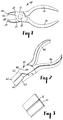
- Fig. 1 is a top view of a corrosion resistant wire cutting tool in accordance with the invention;
- Fig. 2 is a perspective view of a wire cutting tool body in accordance with the invention and generally shows a bottom side; and
- Fig. 3 is a perspective view of a corrosion resistant frangible web cutting tip web adapted to be brazed to the tool body shown in Fig. 1.
- Referring now to Fig. 1, a high precision, high strength, corrosion resistant
wire cutting tool 10 in accordance with the invention includes abody 12 having twohandle sections pivot screw 18. The twohandle sections fingers pivot screw 18 fromhandle sections fingers planar cutting tip - Facing, mating sharpened
cutting edges steel cutting tips cutting edges handles cutting edges - Referring now to Fig. 2, there is shown a rough
cutting tool body 40 havinghandle sections sections cutting tool 10.Handle Sections pivot screw 48.Body 40 hasfingers pivot screw 48 fromrespective handle sections surface having sections fingers cutting tip web 70 shown in Fig. 2. -
Cutting tip web 70 has a longitudinally extending V groove orbreak line 72 centrally located alongplanar web 70.Web 70 is thus constructed to be frangible so that it may be selectively broken along thebreak point 72 to form the facingcutting blade edges -
Tool body 40 is made of a high quality stainless steel such as type 420 or 425M. The cutting tipplanar web member 70 is made of a high performance, corrosion resistant alloy steel such as the Lescalloy BG42 vim-var bearing steel manufactured by Latrobe Steel Company of Latrobe, Pennsylvania. This steel alloy has a composition including by weight 1.15% carbon, 0.30% silicon, 0.50% manganese, 14.50% chromium, 4.00% molybdenum, and 1.20% vanadium. This steel alloy is further described in U.S. patents 3,167,423 and 4,150,978 which are hereby incorporated by reference. - The corrosion resistant, frangible steel cutting
tip web member 70 is brazed to thereceiving surfaces cutting tip web 70 is brazed to receivingsurfaces body 40, the brazing foil and thecutting tip member 70 to a temperature of approximately 1038 degrees C. under vacuum in a magnetic induction heater. The brazing is accomplished with thecutting tip web 70 clamped to thereceiving surfaces web 70 and thereceiving surfaces - After vacuum cooling to a nonoxidizing temperature, the
body 40 with brazed solderedtip 70 is rough ground to form the approximate final product shape as shown for cuttingtool 10 in Fig. 1. Because the alloysteel cutting tips 70 have not yet been hardened, the rough grinding process is somewhat easier than that for prior processes wherein the cutting tips were hardened prior to brazing and rough grinding. - Upon completion of the rough grinding process,
web member 70 was broken alongfracture line 72 in a breaking press to separateweb member 70 into its two separatecutting tip sections frangible web 70 theentire cutting tool 10 is placed on a suitable rack and inserted into a vacuum furnace for the purpose of heat treating thealloy tips - In a preferred heat treating process, the cutting
tool 10 was preheated in a vacuum oven to a temperature of 816 degrees C. It took 15 minutes to reach the preheat temperature which was then maintained for 30 minutes. The temperature was then increased to an austenitizing temperature of 1121 degrees C. with the specified temperature being reached in 15 minutes and being maintained for 30 minutes thereafter. Following the 30 minutes at the austenitizing temperature, the cuttingtool 10 was fan cooled in the atmosphere of an inert gas such as argon to near room temperature for a time of approximately 1 hour and 5 minutes. - Thereafter the
cutting tool 10 was subjected to an air cool at approximately -38 degrees C. After 40 minutes the tool reached the desired temperature of -38 degrees C. and was thereafter maintained at temperature for a period of 2 hours. - Subsequent to cooling, the
tool 10 was tempered at 524 degrees C., requiring approximately 30 minutes to reach temperature, being maintained at the temperature for 2 hours and subsequently being air cooled to room temperature. Thetool 10 with cuttingtips - The above heat treating process was found to produce in the alloy steel corrosion
resistant cutting tips 24, 26 a hardness in the desired range of 62-67 Rc. This hardness has been found by experimentation to be sufficient to withstand long term wire cutting operation while maintaining durability without introducing a brittleness that produces fracturing of cutting edges during use. The heat treating process did not produce separation of the brazed joints even though the maximum temperature was 66 degrees C. higher than the brazing temperature. - Following heat treatment, the
wire cutting tool 10 was subjected to a finish grinding operation, buffed and polished to provide a smooth, shiny appearance. Thereafter thehandle sections pivot screw 18 with shims selected to provide a carefully controlled tightness in the pivot joint. Manufacture of thewire cutting tool 10 was then completed by sharpening the cutting edges 24, 26 in a diamond honing process. Because all portions of thecutting tool 10 are inherently corrosion resistant and made of corrosion resistant material, the additional nickel and chrome plating steps required by prior processes are not required for the improvedwire cutting tool 10. As a result, corrosion cannot be induced by a wearing away of any corrosion protection plating during extended use. The entire cutting tool remains corrosion resistant even in the environment of sterilization procedures when used for orthodontic application. In addition, the nickel foil brazing medium was found to provide a high strength bond of the alloy steelcutting tip web 70 to thebody 40 to virtually eliminate the bonding failures which have been found to occur with prior silver alloy brazing media.
Claims (9)
- A method of manufacturing a cutting tool (10) comprising the steps of:
forming a stainless steel cutting tool body (12) having a receiving surface for matingly receiving a cutting tip;
brazing a corrosion resistant alloy steel cutting tip (24, 26) containing chromium, molybdenum and vanadium to the receiving surface using as a brazing medium a nickel alloy, the brazing being accomplished by heating the receiving surface, cutting tip and brazing medium to a brazing temperature that is sufficient to melt the brazing medium and braze the cutting tip to the receiving surface; and then
heat treating the cutting tool (12-30) subsequent to the brazing step with a treatment that heats the cutting tool to a temperature in excess of the brazing temperature to produce a hardness in the cutting tip in a range of 62-67 on the Rockwell c hardness scale. - A method of manufacturing according to claim 1 wherein the brazing temperature is approximately 1038 degrees C. and the maximum heat treatment temperature is approximately 1121 degrees C.
- A method of manufacture according to claim 1 wherein the tip (24, 26) is made of a high performance bearing steel alloy.
- A method of manufacturing according to claim 1 wherein the cutting tool is a hand held wire cutter.
- A method of manufacturing according to claim 1 wherein the body (12) is composed of a type 420 stainless steel.
- A method of manufacturing according to claim 1 wherein the body (12) is composed of a type 425M stainless steel.
- A method of manufacturing according to claim 1 wherein the tip (24, 26) is composed of a bearing steel including substantially by weight percent the following materials:1.15% carbon0.30% silicon0.50% manganese14.50% chromium4.00% molybdenum1.20% vanadium
- A method of manufacturing according to claim 1 wherein the brazing medium has substantially the following composition by weight percentage:0.02% carbon4.25% siliconless than0.02% phosphorusless than0.02% sulfur7.05% chromium3.09% boron2.89% iron0.09% cobalt0.01% titanium0.01% aluminum0.02% zirconiumBalance nickel
- A method of manufacturing a fully corrosion resistant cutting tool (10) from a stainless steel body (12) and a cutting tip blank (70, 72) consisting of a corrosion resistant alloy steel containing chromium, molybdenum and vanadium, the method comprising the steps of:
brazing the cutting tip blank (70, 72) to the stainless steel body (12) at a brazing temperature using a nickel alloy brazing foil;
rough grinding the body and cutting tip blank to a desired shape after the brazing step to form a rough ground cutting tool having a cutting tip formed from the cutting tip blank;
heat treating the rough ground cutting tool after the rough grinding step to produce a cutting tip hardness in a range of 62-67 on the Rockwell c hardness scale, the heat treating including heating the rough ground cutting tool to an austenitizing temperature for the cutting tip that is in excess of the brazing temperature;
finish grinding the rough ground cutting tool; and
diamond honing the cutting tip of the corrosion resistant cutting tool to form a cutting edge.
Applications Claiming Priority (2)
| Application Number | Priority Date | Filing Date | Title |
|---|---|---|---|
| US07/647,556 US5133812A (en) | 1991-01-29 | 1991-01-29 | Corrosion resistant cutting tool and method of manufacture |
| US647556 | 1991-01-29 |
Publications (3)
| Publication Number | Publication Date |
|---|---|
| EP0497508A2 EP0497508A2 (en) | 1992-08-05 |
| EP0497508A3 EP0497508A3 (en) | 1992-11-25 |
| EP0497508B1 true EP0497508B1 (en) | 1996-06-05 |
Family
ID=24597421
Family Applications (1)
| Application Number | Title | Priority Date | Filing Date |
|---|---|---|---|
| EP92300598A Expired - Lifetime EP0497508B1 (en) | 1991-01-29 | 1992-01-23 | Corrosion resistant cutting tool and method of manufacture |
Country Status (4)
| Country | Link |
|---|---|
| US (1) | US5133812A (en) |
| EP (1) | EP0497508B1 (en) |
| JP (1) | JP2545563Y2 (en) |
| DE (1) | DE69211169T2 (en) |
Families Citing this family (14)
| Publication number | Priority date | Publication date | Assignee | Title |
|---|---|---|---|---|
| US5419047A (en) * | 1993-05-14 | 1995-05-30 | Ormco Corporation | Stainless steel plier-type cutters |
| US5837071A (en) * | 1993-11-03 | 1998-11-17 | Sandvik Ab | Diamond coated cutting tool insert and method of making same |
| US5987752A (en) * | 1998-02-02 | 1999-11-23 | Swanstrom Tools Usa Inc. | Tool for farriers |
| US6257882B1 (en) | 1998-10-19 | 2001-07-10 | 3M Innovative Properties Company | Orthodontic appliances incorporating corrosion resistant nickel-based alloy |
| US6474988B1 (en) | 2000-03-08 | 2002-11-05 | 3M Innovative Properties Company | Hand instrument for debonding orthodontic brackets |
| US7111376B2 (en) | 2003-01-13 | 2006-09-26 | The Stanley Works | Tool with inserted blade members |
| WO2005035798A1 (en) * | 2003-10-08 | 2005-04-21 | Hitachi Metals, Ltd. | Method for producing steel ingot |
| MY151755A (en) * | 2007-12-28 | 2014-06-30 | Shinetsu Chemical Co | Outer blade cutting wheel and making method |
| DE102010037286A1 (en) * | 2010-09-02 | 2012-03-08 | Knipex-Werk C. Gustav Putsch Kg | Schneidzange |
| TR201903983A2 (en) * | 2019-03-18 | 2019-04-22 | Sentes Bir Metalurji Kimya Enerji Uert Ve Ageri Doen Tek San Tic A S | NICKEL BASED HARD SOLDERING ALLOY |
| CN113369573B (en) * | 2021-07-07 | 2024-08-06 | 马鞍山市旭隆冶金机械有限公司 | Cutting edge for cutting steel plate and production process thereof |
| CN113500357A (en) * | 2021-07-20 | 2021-10-15 | 浙江新亚医疗科技股份有限公司 | Tooth orthodontic bending forceps and preparation method thereof |
| CN115415860A (en) * | 2022-09-21 | 2022-12-02 | 杭州沃瑞奥汽车零部件有限公司 | Special cutter for automatic burr grabbing equipment and cutter grinding process |
| FR3166057A1 (en) * | 2024-09-07 | 2026-03-13 | Alain ALCHAAR | Precision Torque Pliers |
Family Cites Families (8)
| Publication number | Priority date | Publication date | Assignee | Title |
|---|---|---|---|---|
| US3167423A (en) * | 1964-04-14 | 1965-01-26 | Latrobe Steel Co | High temperature wear resisting steels |
| US3781993A (en) * | 1972-06-15 | 1974-01-01 | Mann Henry Inc | Light wire pliers for orthodontists |
| US4007524A (en) * | 1974-12-26 | 1977-02-15 | Coats & Clark, Inc. | Cast articulated tool |
| CA1115993A (en) * | 1976-12-15 | 1982-01-12 | Allied Corporation | Homogeneous, ductile brazing foils |
| US4745037A (en) * | 1976-12-15 | 1988-05-17 | Allied Corporation | Homogeneous, ductile brazing foils |
| US4150978A (en) * | 1978-04-24 | 1979-04-24 | Latrobe Steel Company | High performance bearing steels |
| DE3219260A1 (en) * | 1982-05-21 | 1983-11-24 | Lawton GmbH & Co KG, 7200 Tuttlingen | Method of placing a hard material in the recessed stress area of the basic body of a surgical instrument, and a surgical instrument |
| DE9002893U1 (en) * | 1990-03-15 | 1990-08-02 | Kühnert, Eduard, 5650 Solingen | Nail clippers for cosmetics and foot care |
-
1991
- 1991-01-29 US US07/647,556 patent/US5133812A/en not_active Expired - Lifetime
-
1992
- 1992-01-23 EP EP92300598A patent/EP0497508B1/en not_active Expired - Lifetime
- 1992-01-23 DE DE69211169T patent/DE69211169T2/en not_active Expired - Fee Related
- 1992-01-27 JP JP1992002302U patent/JP2545563Y2/en not_active Expired - Lifetime
Also Published As
| Publication number | Publication date |
|---|---|
| DE69211169T2 (en) | 1997-01-23 |
| JPH04112374U (en) | 1992-09-30 |
| EP0497508A3 (en) | 1992-11-25 |
| DE69211169D1 (en) | 1996-07-11 |
| US5133812A (en) | 1992-07-28 |
| EP0497508A2 (en) | 1992-08-05 |
| JP2545563Y2 (en) | 1997-08-25 |
Similar Documents
| Publication | Publication Date | Title |
|---|---|---|
| US5133812A (en) | Corrosion resistant cutting tool and method of manufacture | |
| USRE19182E (en) | Drill and like implement and method | |
| US20130081283A1 (en) | Composite knife blade | |
| US6293020B1 (en) | Cutting instruments | |
| JP5235935B2 (en) | Cutting tool insert and method for producing the same | |
| WO2008130900A1 (en) | Precision sharpener for hunting and asian knives | |
| JP2016073654A (en) | Cutting tool with sharpened blade | |
| US5069872A (en) | Cutting tool | |
| US2335249A (en) | Knife and method of making same | |
| US2414231A (en) | Cutting tool and tip therefor | |
| AU6093290A (en) | Abrasive body | |
| US2579773A (en) | Shears | |
| US1964972A (en) | Method of making cutting tools | |
| CN104647404A (en) | Tool and manufacture method thereof | |
| EP0299740B1 (en) | Method of brazing | |
| JPH06199580A (en) | Joining method for cemented carbide and stainless steel, and therapeutic device made of cemented carbide and stainless steel | |
| US5100045A (en) | Method of reconditioning brazed diamond abrasive tools | |
| CA2257065A1 (en) | Cutting instruments | |
| JPH0568754A (en) | Scissor and manufacture thereof | |
| AU669887B2 (en) | Grinder for dental treatment instruments | |
| JP3847211B2 (en) | Sliding contact and manufacturing method thereof | |
| EP0184455A2 (en) | Bonding method | |
| JPS58151958A (en) | Manufacture of cutting tool | |
| Cera et al. | Corrosion Resistant Cutting Tool and Method of Manufacture | |
| JPH052347B2 (en) |
Legal Events
| Date | Code | Title | Description |
|---|---|---|---|
| PUAI | Public reference made under article 153(3) epc to a published international application that has entered the european phase |
Free format text: ORIGINAL CODE: 0009012 |
|
| AK | Designated contracting states |
Kind code of ref document: A2 Designated state(s): DE FR GB IT |
|
| PUAL | Search report despatched |
Free format text: ORIGINAL CODE: 0009013 |
|
| AK | Designated contracting states |
Kind code of ref document: A3 Designated state(s): DE FR GB IT |
|
| 17P | Request for examination filed |
Effective date: 19930518 |
|
| 17Q | First examination report despatched |
Effective date: 19950317 |
|
| GRAH | Despatch of communication of intention to grant a patent |
Free format text: ORIGINAL CODE: EPIDOS IGRA |
|
| GRAA | (expected) grant |
Free format text: ORIGINAL CODE: 0009210 |
|
| AK | Designated contracting states |
Kind code of ref document: B1 Designated state(s): DE FR GB IT |
|
| REF | Corresponds to: |
Ref document number: 69211169 Country of ref document: DE Date of ref document: 19960711 |
|
| ITF | It: translation for a ep patent filed | ||
| ET | Fr: translation filed | ||
| PLBE | No opposition filed within time limit |
Free format text: ORIGINAL CODE: 0009261 |
|
| 26N | No opposition filed | ||
| PGFP | Annual fee paid to national office [announced via postgrant information from national office to epo] |
Ref country code: FR Payment date: 20010102 Year of fee payment: 10 |
|
| PGFP | Annual fee paid to national office [announced via postgrant information from national office to epo] |
Ref country code: DE Payment date: 20010103 Year of fee payment: 10 |
|
| PGFP | Annual fee paid to national office [announced via postgrant information from national office to epo] |
Ref country code: GB Payment date: 20010105 Year of fee payment: 10 |
|
| REG | Reference to a national code |
Ref country code: GB Ref legal event code: IF02 |
|
| PG25 | Lapsed in a contracting state [announced via postgrant information from national office to epo] |
Ref country code: GB Free format text: LAPSE BECAUSE OF NON-PAYMENT OF DUE FEES Effective date: 20020123 |
|
| PG25 | Lapsed in a contracting state [announced via postgrant information from national office to epo] |
Ref country code: DE Free format text: LAPSE BECAUSE OF NON-PAYMENT OF DUE FEES Effective date: 20020801 |
|
| GBPC | Gb: european patent ceased through non-payment of renewal fee |
Effective date: 20020123 |
|
| PG25 | Lapsed in a contracting state [announced via postgrant information from national office to epo] |
Ref country code: FR Free format text: LAPSE BECAUSE OF NON-PAYMENT OF DUE FEES Effective date: 20020930 |
|
| REG | Reference to a national code |
Ref country code: FR Ref legal event code: ST |
|
| PG25 | Lapsed in a contracting state [announced via postgrant information from national office to epo] |
Ref country code: IT Free format text: LAPSE BECAUSE OF NON-PAYMENT OF DUE FEES;WARNING: LAPSES OF ITALIAN PATENTS WITH EFFECTIVE DATE BEFORE 2007 MAY HAVE OCCURRED AT ANY TIME BEFORE 2007. THE CORRECT EFFECTIVE DATE MAY BE DIFFERENT FROM THE ONE RECORDED. Effective date: 20050123 |