EP0496879B1 - Satellite orbit maintenance system - Google Patents
Satellite orbit maintenance system Download PDFInfo
- Publication number
- EP0496879B1 EP0496879B1 EP91917862A EP91917862A EP0496879B1 EP 0496879 B1 EP0496879 B1 EP 0496879B1 EP 91917862 A EP91917862 A EP 91917862A EP 91917862 A EP91917862 A EP 91917862A EP 0496879 B1 EP0496879 B1 EP 0496879B1
- Authority
- EP
- European Patent Office
- Prior art keywords
- orbit
- satellite
- correction
- velocity correction
- velocity
- Prior art date
- Legal status (The legal status is an assumption and is not a legal conclusion. Google has not performed a legal analysis and makes no representation as to the accuracy of the status listed.)
- Expired - Lifetime
Links
- 238000012423 maintenance Methods 0.000 title abstract description 10
- 238000012937 correction Methods 0.000 claims abstract description 92
- 230000000630 rising effect Effects 0.000 claims abstract description 6
- 238000000034 method Methods 0.000 claims description 18
- 230000000694 effects Effects 0.000 claims description 14
- 230000001174 ascending effect Effects 0.000 claims description 10
- 230000008859 change Effects 0.000 claims description 8
- 230000003247 decreasing effect Effects 0.000 abstract description 2
- 238000004891 communication Methods 0.000 description 5
- 230000007613 environmental effect Effects 0.000 description 4
- 238000013459 approach Methods 0.000 description 2
- 230000008901 benefit Effects 0.000 description 2
- 238000011217 control strategy Methods 0.000 description 2
- 230000008569 process Effects 0.000 description 2
- 239000003380 propellant Substances 0.000 description 2
- PEDCQBHIVMGVHV-UHFFFAOYSA-N Glycerine Chemical compound OCC(O)CO PEDCQBHIVMGVHV-UHFFFAOYSA-N 0.000 description 1
- 230000001186 cumulative effect Effects 0.000 description 1
- 238000010586 diagram Methods 0.000 description 1
- 238000010304 firing Methods 0.000 description 1
- 239000000446 fuel Substances 0.000 description 1
- 238000005259 measurement Methods 0.000 description 1
- 238000012986 modification Methods 0.000 description 1
- 230000004048 modification Effects 0.000 description 1
- 230000000737 periodic effect Effects 0.000 description 1
- 230000009467 reduction Effects 0.000 description 1
- 238000012546 transfer Methods 0.000 description 1
Images

Classifications
-
- B—PERFORMING OPERATIONS; TRANSPORTING
- B64—AIRCRAFT; AVIATION; COSMONAUTICS
- B64G—COSMONAUTICS; VEHICLES OR EQUIPMENT THEREFOR
- B64G1/00—Cosmonautic vehicles
- B64G1/22—Parts of, or equipment specially adapted for fitting in or to, cosmonautic vehicles
- B64G1/24—Guiding or controlling apparatus, e.g. for attitude control
- B64G1/36—Guiding or controlling apparatus, e.g. for attitude control using sensors, e.g. sun-sensors, horizon sensors
-
- B—PERFORMING OPERATIONS; TRANSPORTING
- B64—AIRCRAFT; AVIATION; COSMONAUTICS
- B64G—COSMONAUTICS; VEHICLES OR EQUIPMENT THEREFOR
- B64G1/00—Cosmonautic vehicles
- B64G1/22—Parts of, or equipment specially adapted for fitting in or to, cosmonautic vehicles
- B64G1/24—Guiding or controlling apparatus, e.g. for attitude control
-
- B—PERFORMING OPERATIONS; TRANSPORTING
- B64—AIRCRAFT; AVIATION; COSMONAUTICS
- B64G—COSMONAUTICS; VEHICLES OR EQUIPMENT THEREFOR
- B64G1/00—Cosmonautic vehicles
- B64G1/22—Parts of, or equipment specially adapted for fitting in or to, cosmonautic vehicles
- B64G1/24—Guiding or controlling apparatus, e.g. for attitude control
- B64G1/244—Spacecraft control systems
-
- B—PERFORMING OPERATIONS; TRANSPORTING
- B64—AIRCRAFT; AVIATION; COSMONAUTICS
- B64G—COSMONAUTICS; VEHICLES OR EQUIPMENT THEREFOR
- B64G1/00—Cosmonautic vehicles
- B64G1/22—Parts of, or equipment specially adapted for fitting in or to, cosmonautic vehicles
- B64G1/24—Guiding or controlling apparatus, e.g. for attitude control
- B64G1/26—Guiding or controlling apparatus, e.g. for attitude control using jets
Definitions
- This invention relates generally to techniques for maintaining the orbits of earth-orbiting satellites and, more specifically, to techniques for maintaining such satellites in relatively low-altitude, nearly circular orbits.
- the principal difficulty in maintaining a low earth orbit is that it is continuously degraded by atmospheric drag.
- the conventional process for overcoming drag involves tracking the satellite from the ground, determining the commands needed to raise the orbit, transmitting these commands to the satellite, and executing the commands on the satellite to effect a desired orbital correction. Because of the high cost and potential for error in this communication and computation process, orbital correction maneuvers are typically scheduled as infrequently as possible. As a result, orbit maintenance is not always performed in a most fuel-efficient manner, and the potential life of the satellite is not as long as it might be. Further, the total cost of maintaining a large constellation of satellites by this technique is prohibitively high for many applications.
- the present invention resides in apparatus, and a corresponding method, for maintaining a satellite in an assigned low earth orbit without ground communication or intervention.
- US-A-3 359 407 discloses an earth-orbiting satellite comprising a control system for changing the orbit of the satellite, in particular for effecting a transfer between different types of orbit, which control system comprises: means located on the satellite for sensing at least some of the parameters of the actual orbit of the satellite; orbit correction computation means, also located on the satellite, for computing a velocity correction to be applied to the satellite; and means for applying the computed velocity correction to thrusters on the satellite to effect a velocity correction.
- an earth-orbiting satellite comprising a control system for maintaining the satellite in a desired orbit
- the control system comprising: means located on the satellite for sensing the actual orbit of the satellite; orbit correction computation means, also located on the satellite, for computing a velocity correction to be applied to the satellite; and means for applying the computed velocity correction to thrusters on the satellite; wherein the means for applying the computed velocity correction to the thrusters operates periodically to effect an incremental velocity correction at regular time intervals related to the period of the orbit to maintain the desired orbit; and wherein the orbit correction computation means operates at least once prior to each operation of the means for applying the computed velocity correction to the thrusters.
- the orbit correction computation means operates once per orbit, such as when the satellite crosses the ascending or descending node, i.e. crosses over the earth's equator.
- the means for applying the computed velocity correction also operates once per orbit, ideally at the next apogee point in the orbit after the point at which the computation is made, to raise and circularize the orbit.
- the orbit correction computation means may include means for computing an orbit error, defined as the difference between a measured time of passing a reference point in the orbit and a desired time of passing the same reference point.
- the velocity correction computed by the orbit correction computation means is equal to a predicted velocity correction needed to compensate for atmospheric drag in one complete revolution through the orbit.
- the velocity correction is calculated by multiplying the orbit error value by a gain factor, to bring the satellite more quickly back into the acceptable predefined orbital error range.
- the velocity correction is selected to be less than the prediction-based value, and may be zero, permitting the orbit to decay under the effect of atmospheric drag until the error value is again within the predefined range.
- the invention further provides a method of maintaining a satellite in a desired orbit, the method comprising the steps of: sensing the actual orbit of the satellite using onboard sensing and navigation means; computing, on the satellite, a velocity correction to be applied to the satellite; and applying the computed velocity correction to thrusters on the satellite; wherein the step of applying the computed velocity correction to the thrusters is performed periodically to effect an incremental velocity correction at regular time intervals related to the period of the orbit to maintain the desired orbit; and wherein the step of computing the velocity correction is performed at least once prior to each performance of the step of applying the computed velocity correction to the thrusters.
- the step of periodically computing includes computing an orbit error, defined as the difference between a measured time of passing a reference point in the orbit and a desired time for passing the same reference point.
- the velocity correction computed in the step of periodically computing is equal to a predicted velocity correction needed to compensate for atmospheric drag in one complete revolution through the orbit.
- the velocity correction is calculated by multiplying the orbit error value by a gain factor.
- the velocity correction is selected to be less than the predicted value, and possibly zero, permitting the orbit to decay under the effect of atmospheric drag until the error value is again within the predefined range.
- the present invention represents a significant advance in the field of spacecraft navigation and control.
- the invention provides for autonomous orbit maintenance of satellites using an efficient approach that provides for velocity corrections to be computed and executed, if necessary, on every revolution of the satellite about the earth. So long as the measured position of the satellite in its orbit falls within a positional "box" defining tolerance limits with respect to the desired orbital position, incremental velocity corrections are made based on a prediction of the effect of atmospheric drag on the satellite. If the measured satellite orbit continues to decay in spite of the incremental corrections, the magnitude of the corrections is increased when the measured orbit exceeds the tolerance limits.
- the magnitude of the corrections is reduced, and may be made zero, to permit atmospheric drag to reduce the orbit to the point that the orbital error falls within the tolerance "box" again.
- the present invention is concerned with a system for autonomously maintaining a satellite in a desired low-altitude, nearly circular, earth orbit.
- the system to be described operates autonomously in a single orbiting satellite, the invention may be used to advantage in the maintenance of a large constellation of satellites in assigned orbits providing worldwide communications coverage.
- orbit maintenance has been performed from the ground by determining the present orbit of the satellite, computing a desired orbital correction, transmitting an orbital correction command to the satellite, and executing the command by firing thrusters on the satellite. Since this technique is relatively costly and is prone to error, orbital corrections are usually made very infrequently.
- an orbital correction computation is performed on the satellite, based on autonomous navigation data, and frequent periodic orbital corrections are made, without control or intervention from the ground.
- the system of the invention includes an orbit correction computation module, indicated by reference numeral 10, and a thruster command computation and control module 12.
- the invention uses data from an autonomous navigation sensor 14, and parameters of a desired orbit, as indicated at 16, to compute a velocity correction, which the thruster command and computation control module converts to a pulse width for application to thrusters 18 aligned along a velocity vector of the satellite.
- the desired orbit 16 is stored in memory when the satellite is launched, or may be subsequently changed under ground control, or by an autonomous system on board the satellite. For present purposes, however, the desired orbit is assumed to be fixed in satellite memory.
- the autonomous navigation sensor 14 is an autonomous navigation device providing parameters that define the actual orbit of the satellite.
- Two alternatives are presently contemplated. One is to use the techniques described in pending patent application Serial No. 07/473,715, entitled “Autonomous Spacecraft Navigation System,” by James R. Wertz, assigned to the same assignee as the present application. Basically the techniques disclosed in this prior application involve using observations of the earth, sun and moon to determine spacecraft position and orbit.
- An alternative approach is to use signals received from multiple satellites in the Global Positioning System (GPS).
- GPS Global Positioning System
- the autonomous navigation sensor 14 is then basically a GPS receiver, various versions of which are commercially available.
- the sensor 14 provides parameters that define the observed orbit of the satellite, including ⁇ (measured), the argument of the perigee of the satellite orbit, and T ⁇ (measured), the epoch of the ascending node of the orbit.
- the epoch time defines the time at which the satellite crosses the earth's equator from south to north.
- the ⁇ parameter defines where in the orbit the perigee, or closest point to the earth, is reached.
- the argument of the perigee is the angle of arc, measured in the orbital plane, between the ascending node and the perigee, as seen from a focus of the orbit, which is near the center of the earth for nearly circular orbits.
- the orbit correction computation module 10 uses these two orbital parameters provided from the autonomous navigation sensor 14, together with a desired epoch of the ascending node, T ⁇ , and computes a velocity correction ⁇ V and an epoch T a for the apogee of the orbit, in a manner to be described in more detail.
- Signals indicative of these two values are passed to the thruster command computation and control module 12, which uses the values to compute a pulse width signal (PW) for control of the thrusters 18.
- PW pulse width signal
- the orbit correction computation is performed (by module 10) once every satellite orbit, at the ascending node. If the module 10 determines that there should be a velocity correction, a correctional burn of the thrusters 18 is performed at the next apogee of the satellite, and therefore tends to raise and circularize the orbit. This provides eccentricity control at no additional cost.
- the control system provided by the invention is a hierarchical architecture that uses an active closed orbit control loop around an internal predictive open loop.
- the fundamental control strategy is to control the phasing of the satellite in its orbit while maintaining the period and eccentricity.
- Control inputs are applied with the spacecraft thrusters 18, which change the spacecraft velocity by the commanded amount ⁇ V.
- the magnitude of the applied ⁇ V controls the orbit semi-major axis, and thus the orbit period and spacecraft phasing.
- the time (orbit phase) at which ⁇ V is applied controls the orbit eccentricity.
- the ⁇ V control input is applied at the epoch of the apogee T a .
- the control system used in the invention is based on the observation that an orbiting satellite is a dynamic system with the characteristics of a restoring limit cycle. That is to say, the environment of the satellite acts on the energy state of the satellite in only one direction, to diminish the energy of the orbit and thus reduce the orbit period. Over successive orbits, the phase of the satellite with respect to any reference point moves forward, which means that the time epoch at which the satellite reaches a reference point in the orbit moves backward. This reduction of orbital energy is due to atmospheric drag.
- the control strategy is to add energy to the satellite by applying a control input ⁇ V whenever the phase of the vehicle moves past the reference phase point, and to let the environmental dynamics diminish the orbit energy whenever the phase of the vehicle falls behind the reference phase. An environmental ⁇ V moves the phase of the spacecraft forward, and moves backward the time epoch at which the satellite reaches a reference point in the orbit.
- the reference state for the orbit control system is the epoch time at which the spacecraft passes a well known measured reference point in its orbit.
- the use of a reference epoch provides for direct control of the absolute phasing of the satellite in its orbit, and correspondingly, the relative phasing to other satellites in the constellation being controlled.
- the ascending node provides an excellent phase reference.
- the epoch T ⁇ of the ascending node is used as the reference point.
- an orbit correction involves two control loops: a predictive inner loop and an active closed outer loop.
- the inner control loop applies ⁇ V control inputs to the orbiting spacecraft at levels below the sensing resolution of the navigation system. This is very desirable, as it provides incremental, low-level compensation for the losses in orbit energy due to atmospheric drag on the spacecraft.
- the control system applies a fixed ⁇ V equivalent to the energy loss due to drag. This predictive control is achievable because the drag diminishment of the orbit energy is well defined and may be modeled. For example, the text "Spaceflight Dynamics,” by William Wiesel (McGraw-Hill, 1989) derives an expression for velocity loss due to atmospheric drag. In particular, see equation 3.42 on page 83.
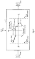
- FIG. 2 shows, inside the block 10, a graph defining the relationship between the computed value of ⁇ V and the measured error ⁇ in the epoch of the ascending node.
- ⁇ T ⁇ (measured) - T ⁇ (reference).
- the value of ⁇ V is obtained from a predicted value, based on a known model of the effect of atmospheric drag.
- the limits of the central band of error values are defined by the measurement resolution of the navigation system employed. Within this central deadband, the orbital errors are so small that they cannot be measured by the navigation system.
- This inner predictive loop is bounded by the outer closed loop, which directly senses the orbit phase of the spacecraft, T ⁇ , and compares this with the reference phase. This difference is used as the error signal that drives the closed control loop. If the error signal is negative, indicating a drift through the one end of the predictive deadband, corresponding to a decaying orbit, the error signal is multiplied by a control gain K to determine the ⁇ V to be applied to null the phase error.
- the outer loop also utilizes the environmental restoring limit cycle to reduce propellant consumption. Thus, if the error is positive and outside the predictive deadband, a ⁇ V of zero is used, since the environmental effects of atmospheric drag will apply sufficient ⁇ V to compensate for the error and bring it back within the predictive deadband.
- Other control laws may be used in the outer active control loop. In general, though, the velocity correction will be increased to some degree on one side of the predictive deadband, and decreased to some degree on the other side.
- a single application of the ⁇ V (predicted) used in the restrictive deadband is not sufficient to affect the orbit as observed by the autonomous navigation sensor 14, but repeated applications of the ⁇ V on each revolution of the satellite usually have a cumulative effect that is eventually recognized in the measured values of T ⁇ and ⁇ . If the predicted effect of atmospheric drag is very accurate, the control system may remain in the central deadband for much of the time. To further improve the efficiency of the control system, the fixed velocity correction applied in the predictive deadband may be adjusted from time to time, based on the tendency of the system to move into the outer active control loop.
- the present invention represents a significant advance in the field of spacecraft navigation and orbit maintenance.
- the invention provides for the autonomous maintenance of an assigned orbit, with no control or intervention from the ground, except to the extent that ground support may be needed for GPS position determination.
- the system of the invention eliminates the effects of possible communication errors during orbital corrections, and the need to store commands in the satellite.
- the invention also maximizes propellant efficiency and minimizes thruster size and weight for a given mission.
- the system of the invention maintains tighter control over the constellation structure.
- the potential for catastrophic error during a large thruster burn is practically eliminated, since all thruster burns are of short duration.
Landscapes
- Engineering & Computer Science (AREA)
- Remote Sensing (AREA)
- Chemical & Material Sciences (AREA)
- Combustion & Propulsion (AREA)
- Radar, Positioning & Navigation (AREA)
- Aviation & Aerospace Engineering (AREA)
- Automation & Control Theory (AREA)
- Control Of Position, Course, Altitude, Or Attitude Of Moving Bodies (AREA)
Abstract
Description
- This invention relates generally to techniques for maintaining the orbits of earth-orbiting satellites and, more specifically, to techniques for maintaining such satellites in relatively low-altitude, nearly circular orbits. Some applications of satellite communications require the launching and maintenance of many satellites in low earth orbits.
- The principal difficulty in maintaining a low earth orbit is that it is continuously degraded by atmospheric drag. The conventional process for overcoming drag involves tracking the satellite from the ground, determining the commands needed to raise the orbit, transmitting these commands to the satellite, and executing the commands on the satellite to effect a desired orbital correction. Because of the high cost and potential for error in this communication and computation process, orbital correction maneuvers are typically scheduled as infrequently as possible. As a result, orbit maintenance is not always performed in a most fuel-efficient manner, and the potential life of the satellite is not as long as it might be. Further, the total cost of maintaining a large constellation of satellites by this technique is prohibitively high for many applications.
- Ideally, what is needed is a system for making orbital corrections on a more frequent and reliable basis, without the high cost and potential for catastrophic errors associated with ground-based control. The present invention satisfies this need.
- The present invention resides in apparatus, and a corresponding method, for maintaining a satellite in an assigned low earth orbit without ground communication or intervention.
- US-A-3 359 407 discloses an earth-orbiting satellite comprising a control system for changing the orbit of the satellite, in particular for effecting a transfer between different types of orbit, which control system comprises: means located on the satellite for sensing at least some of the parameters of the actual orbit of the satellite; orbit correction computation means, also located on the satellite, for computing a velocity correction to be applied to the satellite; and means for applying the computed velocity correction to thrusters on the satellite to effect a velocity correction.
- The present inventionn provides an earth-orbiting satellite comprising a control system for maintaining the satellite in a desired orbit, the control system comprising: means located on the satellite for sensing the actual orbit of the satellite; orbit correction computation means, also located on the satellite, for computing a velocity correction to be applied to the satellite; and means for applying the computed velocity correction to thrusters on the satellite; wherein the means for applying the computed velocity correction to the thrusters operates periodically to effect an incremental velocity correction at regular time intervals related to the period of the orbit to maintain the desired orbit; and wherein the orbit correction computation means operates at least once prior to each operation of the means for applying the computed velocity correction to the thrusters.
- In an embodiment of the invention, the orbit correction computation means operates once per orbit, such as when the satellite crosses the ascending or descending node, i.e. crosses over the earth's equator. The means for applying the computed velocity correction also operates once per orbit, ideally at the next apogee point in the orbit after the point at which the computation is made, to raise and circularize the orbit.
- More specifically, the orbit correction computation means may include means for computing an orbit error, defined as the difference between a measured time of passing a reference point in the orbit and a desired time of passing the same reference point. When the orbit error is within a predefined range, the velocity correction computed by the orbit correction computation means is equal to a predicted velocity correction needed to compensate for atmospheric drag in one complete revolution through the orbit. Although a single application of the predicted velocity correction is insufficient to make a detectable change in the orbit, repeated applications of this prediction-bases velocity change keeps the satellite in its desired orbit with a minimum of fuel consumption.
- For orbit error values outside the predefined range and in a direction indicative of a decaying orbit, the velocity correction is calculated by multiplying the orbit error value by a gain factor, to bring the satellite more quickly back into the acceptable predefined orbital error range. For orbit error values outside the predefined range and in a direction indicative of a rising orbit, the velocity correction is selected to be less than the prediction-based value, and may be zero, permitting the orbit to decay under the effect of atmospheric drag until the error value is again within the predefined range.
- The invention further provides a method of maintaining a satellite in a desired orbit, the method comprising the steps of: sensing the actual orbit of the satellite using onboard sensing and navigation means; computing, on the satellite, a velocity correction to be applied to the satellite; and applying the computed velocity correction to thrusters on the satellite; wherein the step of applying the computed velocity correction to the thrusters is performed periodically to effect an incremental velocity correction at regular time intervals related to the period of the orbit to maintain the desired orbit; and wherein the step of computing the velocity correction is performed at least once prior to each performance of the step of applying the computed velocity correction to the thrusters.
- More specifically, the step of periodically computing includes computing an orbit error, defined as the difference between a measured time of passing a reference point in the orbit and a desired time for passing the same reference point. When the orbit error is within a predefined range, the velocity correction computed in the step of periodically computing is equal to a predicted velocity correction needed to compensate for atmospheric drag in one complete revolution through the orbit. For orbit error values outside the predefined range and in a direction indicative of a decaying orbit, the velocity correction is calculated by multiplying the orbit error value by a gain factor. For orbit error values outside the predefined range and in a direction indicative of a rising orbit, the velocity correction is selected to be less than the predicted value, and possibly zero, permitting the orbit to decay under the effect of atmospheric drag until the error value is again within the predefined range.
- It will be appreciated from the foregoing that the present invention represents a significant advance in the field of spacecraft navigation and control. In particular, the invention provides for autonomous orbit maintenance of satellites using an efficient approach that provides for velocity corrections to be computed and executed, if necessary, on every revolution of the satellite about the earth. So long as the measured position of the satellite in its orbit falls within a positional "box" defining tolerance limits with respect to the desired orbital position, incremental velocity corrections are made based on a prediction of the effect of atmospheric drag on the satellite. If the measured satellite orbit continues to decay in spite of the incremental corrections, the magnitude of the corrections is increased when the measured orbit exceeds the tolerance limits. If the measured satellite orbit exceeds the tolerance limits in the other direction, and the incremental corrections result in a rising orbit, the magnitude of the corrections is reduced, and may be made zero, to permit atmospheric drag to reduce the orbit to the point that the orbital error falls within the tolerance "box" again.
- Other aspects and advantages of the invention will become apparent from the following more detailed description, taken in conjunction with the accompanying drawings.
-
- FIGURE 1 is a block diagram of an autonomous orbit maintenance system in accordance with the invention; and
- FIG. 2 is a diagrammatic view illustrating graphically how the orbit correction computation is performed in the system of the invention.
- As shown in the drawings for purposes of illustration, the present invention is concerned with a system for autonomously maintaining a satellite in a desired low-altitude, nearly circular, earth orbit. Although the system to be described operates autonomously in a single orbiting satellite, the invention may be used to advantage in the maintenance of a large constellation of satellites in assigned orbits providing worldwide communications coverage.
- Conventionally, orbit maintenance has been performed from the ground by determining the present orbit of the satellite, computing a desired orbital correction, transmitting an orbital correction command to the satellite, and executing the command by firing thrusters on the satellite. Since this technique is relatively costly and is prone to error, orbital corrections are usually made very infrequently.
- In accordance with the invention, an orbital correction computation is performed on the satellite, based on autonomous navigation data, and frequent periodic orbital corrections are made, without control or intervention from the ground. Other aspects of the invention will become apparent from the following discussion of the figures.
- As shown in FIG. 1, the system of the invention includes an orbit correction computation module, indicated by
reference numeral 10, and a thruster command computation andcontrol module 12. The invention uses data from anautonomous navigation sensor 14, and parameters of a desired orbit, as indicated at 16, to compute a velocity correction, which the thruster command and computation control module converts to a pulse width for application tothrusters 18 aligned along a velocity vector of the satellite. - The desired
orbit 16 is stored in memory when the satellite is launched, or may be subsequently changed under ground control, or by an autonomous system on board the satellite. For present purposes, however, the desired orbit is assumed to be fixed in satellite memory. - The
autonomous navigation sensor 14 is an autonomous navigation device providing parameters that define the actual orbit of the satellite. Two alternatives are presently contemplated. One is to use the techniques described in pending patent application Serial No. 07/473,715, entitled "Autonomous Spacecraft Navigation System," by James R. Wertz, assigned to the same assignee as the present application. Basically the techniques disclosed in this prior application involve using observations of the earth, sun and moon to determine spacecraft position and orbit. An alternative approach is to use signals received from multiple satellites in the Global Positioning System (GPS). Theautonomous navigation sensor 14 is then basically a GPS receiver, various versions of which are commercially available. In any event, thesensor 14 provides parameters that define the observed orbit of the satellite, including ω(measured), the argument of the perigee of the satellite orbit, and TΩ(measured), the epoch of the ascending node of the orbit. The epoch time defines the time at which the satellite crosses the earth's equator from south to north. The ω parameter defines where in the orbit the perigee, or closest point to the earth, is reached. The argument of the perigee is the angle of arc, measured in the orbital plane, between the ascending node and the perigee, as seen from a focus of the orbit, which is near the center of the earth for nearly circular orbits. - The orbit
correction computation module 10 uses these two orbital parameters provided from theautonomous navigation sensor 14, together with a desired epoch of the ascending node, TΩ, and computes a velocity correction ΔV and an epoch Ta for the apogee of the orbit, in a manner to be described in more detail. Signals indicative of these two values are passed to the thruster command computation andcontrol module 12, which uses the values to compute a pulse width signal (PW) for control of thethrusters 18. This computation is well known in the art of rocket propulsion. There is a simple relationship between the performance characteristics of the thrusters, the mass of the satellite, and the "burn" time or pulse width needed to achieve a given change in satellite velocity. - In accordance with one important aspect of the invention, the orbit correction computation is performed (by module 10) once every satellite orbit, at the ascending node. If the
module 10 determines that there should be a velocity correction, a correctional burn of thethrusters 18 is performed at the next apogee of the satellite, and therefore tends to raise and circularize the orbit. This provides eccentricity control at no additional cost. - The control system provided by the invention is a hierarchical architecture that uses an active closed orbit control loop around an internal predictive open loop. The fundamental control strategy is to control the phasing of the satellite in its orbit while maintaining the period and eccentricity. Control inputs are applied with the
spacecraft thrusters 18, which change the spacecraft velocity by the commanded amount ΔV. The magnitude of the applied ΔV controls the orbit semi-major axis, and thus the orbit period and spacecraft phasing. The time (orbit phase) at which ΔV is applied controls the orbit eccentricity. In the presently preferred embodiment of the invention, the ΔV control input is applied at the epoch of the apogee Ta. - The control system used in the invention is based on the observation that an orbiting satellite is a dynamic system with the characteristics of a restoring limit cycle. That is to say, the environment of the satellite acts on the energy state of the satellite in only one direction, to diminish the energy of the orbit and thus reduce the orbit period. Over successive orbits, the phase of the satellite with respect to any reference point moves forward, which means that the time epoch at which the satellite reaches a reference point in the orbit moves backward. This reduction of orbital energy is due to atmospheric drag. The control strategy is to add energy to the satellite by applying a control input ΔV whenever the phase of the vehicle moves past the reference phase point, and to let the environmental dynamics diminish the orbit energy whenever the phase of the vehicle falls behind the reference phase. An environmental ΔV moves the phase of the spacecraft forward, and moves backward the time epoch at which the satellite reaches a reference point in the orbit.
- The reference state for the orbit control system is the epoch time at which the spacecraft passes a well known measured reference point in its orbit. The use of a reference epoch provides for direct control of the absolute phasing of the satellite in its orbit, and correspondingly, the relative phasing to other satellites in the constellation being controlled. For a spacecraft with a nonequatorial orbit, the ascending node provides an excellent phase reference. In the illustrative embodiment of the invention, the epoch TΩ of the ascending node is used as the reference point.
- As mentioned above, the computation of an orbit correction involves two control loops: a predictive inner loop and an active closed outer loop. The inner control loop applies ΔV control inputs to the orbiting spacecraft at levels below the sensing resolution of the navigation system. This is very desirable, as it provides incremental, low-level compensation for the losses in orbit energy due to atmospheric drag on the spacecraft. The control system applies a fixed ΔV equivalent to the energy loss due to drag. This predictive control is achievable because the drag diminishment of the orbit energy is well defined and may be modeled. For example, the text "Spaceflight Dynamics," by William Wiesel (McGraw-Hill, 1989) derives an expression for velocity loss due to atmospheric drag. In particular, see equation 3.42 on page 83.
- FIG. 2 shows, inside the
block 10, a graph defining the relationship between the computed value of ΔV and the measured error ε in the epoch of the ascending node. The error is given by:

For a central band of values of ε, symmetrical about a zero value, the value of ΔV is obtained from a predicted value, based on a known model of the effect of atmospheric drag. The limits of the central band of error values are defined by the measurement resolution of the navigation system employed. Within this central deadband, the orbital errors are so small that they cannot be measured by the navigation system. - This inner predictive loop is bounded by the outer closed loop, which directly senses the orbit phase of the spacecraft, TΩ, and compares this with the reference phase. This difference is used as the error signal that drives the closed control loop. If the error signal is negative, indicating a drift through the one end of the predictive deadband, corresponding to a decaying orbit, the error signal is multiplied by a control gain K to determine the ΔV to be applied to null the phase error. The outer loop also utilizes the environmental restoring limit cycle to reduce propellant consumption. Thus, if the error is positive and outside the predictive deadband, a ΔV of zero is used, since the environmental effects of atmospheric drag will apply sufficient ΔV to compensate for the error and bring it back within the predictive deadband. Other control laws may be used in the outer active control loop. In general, though, the velocity correction will be increased to some degree on one side of the predictive deadband, and decreased to some degree on the other side.
- A single application of the ΔV (predicted) used in the restrictive deadband is not sufficient to affect the orbit as observed by the
autonomous navigation sensor 14, but repeated applications of the ΔV on each revolution of the satellite usually have a cumulative effect that is eventually recognized in the measured values of TΩ and ω. If the predicted effect of atmospheric drag is very accurate, the control system may remain in the central deadband for much of the time. To further improve the efficiency of the control system, the fixed velocity correction applied in the predictive deadband may be adjusted from time to time, based on the tendency of the system to move into the outer active control loop. - It will be appreciated from the foregoing that the present invention represents a significant advance in the field of spacecraft navigation and orbit maintenance. In particular, the invention provides for the autonomous maintenance of an assigned orbit, with no control or intervention from the ground, except to the extent that ground support may be needed for GPS position determination. The system of the invention eliminates the effects of possible communication errors during orbital corrections, and the need to store commands in the satellite. The invention also maximizes propellant efficiency and minimizes thruster size and weight for a given mission. For applications requiring large constellations of satellites, the system of the invention maintains tighter control over the constellation structure. Moreover, the potential for catastrophic error during a large thruster burn is practically eliminated, since all thruster burns are of short duration.
- It will also be appreciated that, although an embodiment of the invention has been described in detail for purposes of illustration, various modifications may be made without departing from the scope of the invention as defined by the appended claims.
Claims (12)
- An earth-orbiting satellite comprising a control system for maintaining the satellite in a desired orbit, the control system comprising:
means (14) located on the satellite for sensing the actual orbit of the satellite;
orbit correction computation means (10), also located on the satellite, for computing a velocity correction to be applied to the satellite; and
means (12) for applying the computed velocity correction to thrusters (18) on the satellite;
wherein the means (12) for applying the computed velocity correction to the thrusters (18) operates periodically to effect an incremental velocity correction at regular time intervals related to the period of the orbit; to maintain the desired orbit;
and wherein the orbit correction computation means (10) operates at least once prior to each operation of the means (12) for applying the computed velocity correction to the thrusters (18). - A satellite as defined in Claim 1, wherein:
wherein:
the orbit correction computation means (10) operates once per orbit; and
the means (12) for applying the computed velocity correction also operates once per orbit. - A satellite as defined in Claim 2, wherein:
the orbit correction computation means (10) operates each time the satellite passes through an ascending or descending node;
the means (12) for applying the computed velocity correction operates at each apogee of the orbit, to raise and circularize the orbit. - A satellite as defined in Claim 1, wherein:
the orbit correction computation means (10) includes means for computing an orbit error, defined as the difference between a measured time of passing a reference point in the orbit and a desired time of passing the same reference point; and
the velocity correction computed by the orbit correction computation means (10) when the orbit error is within a predefined range, is equal to a predicted velocity correction needed to compensate for atmospheric drag in one complete revolution through the orbit;
whereby orbital correction is effected even through each incremental velocity change may be insufficient to make a detectable change in the orbit. - A satellite as defined in Claim 4, wherein:
for orbit error values outside the predefined range and in a direction indicative of a decaying orbit, the velocity correction is calculated by multiplying the orbit error value by a gain factor. - A satellite as defined in Claim 5, wherein:
for orbit error values outside the predefined range and in a direction indicative or a rising orbit, the velocity correction is selected to be zero, permitting the orbit to decay under the effect of atmospheric drag, until the error value is again within the predefined range. - A method of maintaining a satellite in a desired orbit, the method comprising the steps of:
sensing the actual orbit of the satellite using onboard sensing the navigation means (14);
computing, on the satellite, a velocity correction to be applied to the satellite; and
applying the computed velocity correction to thrusters (18) on the satellite;
wherein the step of applying the computed velocity correction to the thrusters (18) is performed periodically to effect an incremental velocity correction at regular time intervals related to the period of the orbit to maintain the desired orbit; and wherein the step of computing the velocity correction is performed at least once prior to each performance of the step of applying the computed velocity correction to the thrusters (18). - A method as defined in Claim 7, wherein:
the computing step is performed once per orbit; and
the step of applying the computed velocity correction is also performed once per orbit. - A method as defined in Claim 8, wherein:
the computing step is performed each time the satellite passes through an ascending or descending node;
the step of applying the computed velocity correction operates at each apogee of the orbit, to raise the circularize the orbit. - A method as defined in Claim 7, wherein:
the step of periodically computing includes computing an orbit error, defined as the difference between a measured time of passing a reference point in the orbit and a desired time for passing the same reference point; and,
when the orbit error is within a predefined range, the velocity correction computed in the step of periodically computing is equal to a predicted velocity correction needed to compensate for atmospheric drag in the complete revolution through the orbit;
whereby orbital correction is effected even though each incremental velocity change may be insufficient to make a detectable change in the orbit. - A method as defined in Claim 10, wherein:
for orbit error values outside the predefined range and in a direction indicative of a decaying orbit, the velocity correction is calculated by multiplying the orbit error value by a gain factor. - A method as defined in Claim 11, wherein:
for orbit error values outside the predefined range and in a direction indicative of a rising orbit, the velocity correction is selected to be zero, permitting the orbit to decay under the effect of atmospheric drag, until the error value is again within the predefined range.
Applications Claiming Priority (3)
| Application Number | Priority Date | Filing Date | Title |
|---|---|---|---|
| US57150890A | 1990-08-22 | 1990-08-22 | |
| PCT/US1991/006008 WO1992003339A1 (en) | 1990-08-22 | 1991-08-22 | Satellite orbit maintenance system |
| US571508 | 2000-05-15 |
Publications (3)
| Publication Number | Publication Date |
|---|---|
| EP0496879A1 EP0496879A1 (en) | 1992-08-05 |
| EP0496879A4 EP0496879A4 (en) | 1992-08-12 |
| EP0496879B1 true EP0496879B1 (en) | 1995-04-26 |
Family
ID=24283989
Family Applications (1)
| Application Number | Title | Priority Date | Filing Date |
|---|---|---|---|
| EP91917862A Expired - Lifetime EP0496879B1 (en) | 1990-08-22 | 1991-08-22 | Satellite orbit maintenance system |
Country Status (4)
| Country | Link |
|---|---|
| US (1) | US5528502A (en) |
| EP (1) | EP0496879B1 (en) |
| DE (1) | DE69109266T2 (en) |
| WO (1) | WO1992003339A1 (en) |
Families Citing this family (41)
| Publication number | Priority date | Publication date | Assignee | Title |
|---|---|---|---|---|
| DE19703629A1 (en) * | 1997-01-31 | 1998-08-06 | Daimler Benz Aerospace Ag | Method for autonomously determining the position of a satellite |
| DE4129627C2 (en) * | 1991-09-06 | 1994-08-04 | Deutsche Aerospace | Device and method for position control of a spacecraft to be rotated about a body-fixed axis |
| US5687084A (en) * | 1992-05-26 | 1997-11-11 | Microcosm, Inc. | Satellite orbit maintenance system |
| US5862495A (en) * | 1996-09-18 | 1999-01-19 | Lockheed Martin Corp. | Real time position correction to ground generated spacecraft ephemeris |
| CA2273932A1 (en) * | 1996-12-05 | 1998-06-11 | Shabbir Ahmed Parvez | Autonomous guidance system with position and velocity feedback using modern control theory |
| US5951607A (en) * | 1997-03-06 | 1999-09-14 | The United States Of America As Represented By The Secretary Of The Navy | Autonomous craft controller system for landing craft air cushioned vehicle |
| KR100221559B1 (en) * | 1997-05-15 | 1999-09-15 | 정선종 | On board Autonomous Satellite Control Method |
| US5935196A (en) * | 1997-06-11 | 1999-08-10 | Itt Manufacturing Enterprises | Technique for the use of GPS for high orbiting satellites |
| US6154692A (en) * | 1997-10-01 | 2000-11-28 | Space Systems/Loral, Inc. | Spacecraft yaw pointing for inclined orbits |
| FR2774828B1 (en) * | 1998-02-06 | 2000-04-21 | Centre Nat Etd Spatiales | SPACE TELECOMMUNICATIONS SYSTEM INCLUDING AT LEAST ONE SATELLITE, AND PROCESS FOR SYNCHRONIZING SUCH A SYSTEM |
| US6266584B1 (en) * | 1998-03-31 | 2001-07-24 | Space Systems/Loral, Inc. | Robust autonomous GPS time reference for space application |
| US5957982A (en) * | 1998-08-18 | 1999-09-28 | Trw Inc. | Method and system for space navigation |
| US6859769B1 (en) * | 1999-01-26 | 2005-02-22 | Analytical Graphics, Inc. | Method and apparatus for creating elements and systems for description of position and motion of bodies in three-dimensional space to support orbital maneuver analysis |
| US6341249B1 (en) | 1999-02-11 | 2002-01-22 | Guang Qian Xing | Autonomous unified on-board orbit and attitude control system for satellites |
| US6431496B1 (en) | 1999-02-12 | 2002-08-13 | Hughes Electronics Corporation | Method and apparatus for operating satellites in orbit |
| DE19907235A1 (en) * | 1999-02-19 | 2000-09-14 | Daimler Chrysler Ag | GPS navigation system for space applications |
| US6373023B1 (en) | 1999-03-02 | 2002-04-16 | General Dynamics (Ots) Aerospace, Inc. | ARC discharge initiation for a pulsed plasma thruster |
| US6186446B1 (en) * | 1999-06-08 | 2001-02-13 | Space Systems/Loral, Inc. | Solar array control for electric propulsion system |
| EP1076005B1 (en) * | 1999-08-13 | 2007-01-03 | Hughes Electronics Corporation | Spacecraft orbit control using orbit position feedback |
| JP2001099907A (en) * | 1999-10-04 | 2001-04-13 | Chiba Inst Of Technology | Signal source positioning satellite system |
| US6314344B1 (en) | 2000-03-17 | 2001-11-06 | Space Systems/Loral, Inc. | Automated orbit compensation system and method |
| FR2829247B1 (en) * | 2001-09-04 | 2007-04-06 | Centre Nat Etd Spatiales | METHOD FOR AUTONOMOUS ORBIT CONTROL OF A SATELLITE, AND AUTONOMOUS CONTROLLED ORBIT SATELLITE |
| FR2836450B1 (en) * | 2002-02-25 | 2004-12-03 | Centre Nat Etd Spatiales | SPACE VEHICLE AND METHOD FOR DRIVING SUCH A VEHICLE |
| US6830222B1 (en) | 2002-03-21 | 2004-12-14 | Global Aerospace Corporation | Balloon device for lowering space object orbits |
| US7725259B2 (en) * | 2007-05-03 | 2010-05-25 | Raytheon Company | Trajectory estimation system for an orbiting satellite |
| US8115994B2 (en) * | 2007-07-10 | 2012-02-14 | Lockheed Martin Corporation | Scanning wide field telescope and method |
| JP5439980B2 (en) * | 2009-06-26 | 2014-03-12 | 三菱電機株式会社 | Orbit determination apparatus and orbit determination method |
| US8448903B2 (en) * | 2011-01-21 | 2013-05-28 | Kratos Integral Holdings, Llc | Longitude-drift phase plane control with continuous or quasi-continuous maneuvers |
| CN102880184B (en) * | 2012-10-24 | 2015-05-27 | 北京控制工程研究所 | Autonomous orbit control method for stationary orbit satellite |
| US10313010B2 (en) * | 2015-03-17 | 2019-06-04 | The Boeing Company | Laser communications in super-geosynchronous earth orbit |
| US10009101B2 (en) | 2015-03-17 | 2018-06-26 | The Boeing Company | Laser communications following an atmospheric event |
| CN105173120B (en) * | 2015-09-21 | 2017-03-22 | 上海卫星工程研究所 | Control method for in-orbit automatic job task implementation of satellite |
| CN105253330B (en) * | 2015-10-30 | 2017-04-05 | 中国空间技术研究院 | A kind of information fusion GEO satellite control system menu-type design method based on optimization |
| US10180686B2 (en) * | 2016-03-17 | 2019-01-15 | Mitsubishi Electric Research Laboratories, Inc. | Concurrent station keeping, attitude control, and momentum management of spacecraft |
| CN109445449B (en) * | 2018-11-29 | 2019-10-22 | 浙江大学 | A high subsonic UAV ultra-low altitude flight control system and method |
| WO2021102669A1 (en) * | 2019-11-26 | 2021-06-03 | 中国科学院微小卫星创新研究院 | Autonomous maintenance method for ultra-low orbit satellites |
| CN113031638B (en) * | 2021-03-10 | 2022-08-23 | 哈尔滨工业大学 | Constellation deployment method, device and storage medium based on time-sharing phase modulation of low-thrust satellite |
| CN113848567B (en) * | 2021-08-26 | 2023-05-30 | 深圳市魔方卫星科技有限公司 | SAR satellite in-plane optimal orbit control determination method, device and related equipment |
| GB2612359B (en) * | 2021-10-29 | 2025-10-01 | Iceye Oy | Satellite operation and processing of satellite state data |
| CN115098828B (en) * | 2022-08-26 | 2022-11-04 | 北京控制工程研究所 | Method and device for calculating low-orbit satellite orbit in near circle |
| CN117087875B (en) * | 2023-10-20 | 2023-12-29 | 北京控制工程研究所 | Autonomous closed-loop orbit control method and device for spacecraft |
Family Cites Families (25)
| Publication number | Priority date | Publication date | Assignee | Title |
|---|---|---|---|---|
| US3359407A (en) * | 1959-10-28 | 1967-12-19 | Gen Electric | Satellite orbit changing system |
| US3866025A (en) * | 1972-03-17 | 1975-02-11 | Rca Corp | Spacecraft attitude control system |
| US3944172A (en) * | 1972-04-14 | 1976-03-16 | Erno Raumfahrttechnik Gmbh | Attitude control for space vehicle |
| US4102958A (en) * | 1974-05-02 | 1978-07-25 | Owens-Illinois, Inc. | Method of controlling an extruder |
| DE2642061C2 (en) * | 1976-09-18 | 1983-11-24 | Messerschmitt-Bölkow-Blohm GmbH, 8000 München | Position control and orbit change method for a three-axis stabilizable satellite, in particular for a geostationary satellite and device for carrying out the method |
| DE2749868C3 (en) * | 1977-11-08 | 1980-05-22 | Messerschmitt-Boelkow-Blohm Gmbh, 8000 Muenchen | Sun and earth detection methods for satellites |
| US4161780A (en) * | 1978-06-23 | 1979-07-17 | The United States Of America As Represented By The Secretary Of The Navy | Spin rate timing system |
| US4599697A (en) * | 1982-08-11 | 1986-07-08 | Ford Aerospace & Communications Corporation | Digital PWPF three axis spacecraft attitude control |
| US4617634A (en) * | 1983-06-28 | 1986-10-14 | Mitsubishi Denki Kabushiki Kaisha | Artificial satellite attitude control system |
| US4730798A (en) * | 1985-03-08 | 1988-03-15 | Wertz James R | Autonomous spacecraft controller and related method |
| US4837699A (en) * | 1985-07-18 | 1989-06-06 | Hughes Aircraft Company | Method for controlling the spin axis attitude of a spinning spacecraft |
| JP2518212B2 (en) * | 1986-06-26 | 1996-07-24 | 日本電気株式会社 | Orbit control method for artificial satellites |
| US4776540A (en) * | 1986-10-03 | 1988-10-11 | Communications Satellite Corporation | Method of orienting a synchronous satellite |
| CA1334292C (en) * | 1986-10-06 | 1995-02-07 | Andrew E. Turner | Apogee at constant time-of-day equatorial (ace) orbit |
| US4911385A (en) * | 1987-04-30 | 1990-03-27 | Agrawal Brij N | Attitude pointing error correction system and method for geosynchronous satellites |
| WO1990001447A1 (en) * | 1988-08-12 | 1990-02-22 | Nippon Telegraph And Telephone Corporation | Method and apparatus for changing orbit of artificial satellite |
| FR2637565B1 (en) * | 1988-10-06 | 1991-01-11 | Aerospatiale | ACTIVE CONTROL SYSTEM BASED ON THREE AXES OF THE ATTITUDE OF A GEOSTATIONARY SATELLITE |
| FR2637564B1 (en) * | 1988-10-06 | 1994-10-14 | Aerospatiale | METHOD AND SYSTEM FOR AUTONOMOUS ORBIT CONTROL OF A GEOSTATIONARY SATELLITE |
| DE3922761C2 (en) * | 1989-07-11 | 1994-08-25 | Deutsche Aerospace | Method and device for aligning a geostationary satellite in a reference direction |
| US5050087A (en) * | 1989-11-29 | 1991-09-17 | Westinghouse Electric Corp. | System and method for providing accurate attitude measurements at remote locations within an aircraft |
| US5109346A (en) * | 1990-02-01 | 1992-04-28 | Microcosm, Inc. | Autonomous spacecraft navigation system |
| FR2670746B1 (en) * | 1990-12-21 | 1993-04-16 | Aerospatiale | ATTITUDE MONITORING SYSTEM FOR 3-AXIS SATELLITE ,; IN PARTICULAR FOR OBSERVATION SATELLITE. |
| US5222023A (en) * | 1991-04-02 | 1993-06-22 | Space Systems/Loral, Inc. | Compensated transition for spacecraft attitude control |
| US5267167A (en) * | 1991-05-10 | 1993-11-30 | Ball Corporation | Method and system for formationfinding and formationkeeping in a constellation of satellites |
| US5227802A (en) * | 1991-12-23 | 1993-07-13 | Motorola, Inc. | Satellite system cell management |
-
1991
- 1991-08-22 WO PCT/US1991/006008 patent/WO1992003339A1/en not_active Ceased
- 1991-08-22 DE DE69109266T patent/DE69109266T2/en not_active Expired - Fee Related
- 1991-08-22 EP EP91917862A patent/EP0496879B1/en not_active Expired - Lifetime
-
1992
- 1992-05-26 US US07/890,368 patent/US5528502A/en not_active Expired - Lifetime
Also Published As
| Publication number | Publication date |
|---|---|
| EP0496879A4 (en) | 1992-08-12 |
| DE69109266D1 (en) | 1995-06-01 |
| DE69109266T2 (en) | 1995-08-24 |
| US5528502A (en) | 1996-06-18 |
| EP0496879A1 (en) | 1992-08-05 |
| WO1992003339A1 (en) | 1992-03-05 |
Similar Documents
| Publication | Publication Date | Title |
|---|---|---|
| US5528502A (en) | Satellite orbit maintenance system | |
| US5687084A (en) | Satellite orbit maintenance system | |
| EP0769736B1 (en) | Method for inclined orbit attitude control for momentum bias spacecraft | |
| US6341249B1 (en) | Autonomous unified on-board orbit and attitude control system for satellites | |
| EP0568209B1 (en) | Spacecraft attitude control and momentum unloading using gimballed and throttled thrusters | |
| US5692707A (en) | Universal spacecraft attitude steering control system | |
| US5130931A (en) | Spacecraft attitude and velocity control system | |
| US7877173B2 (en) | Method and apparatus for determining a satellite attitude using crosslink reference signals | |
| US6691033B1 (en) | System and method for calibrating inter-star-tracker misalignments in a stellar inertial attitude determination system | |
| US6845950B1 (en) | System for high efficiency spacecraft orbit transfer | |
| EP0785132A1 (en) | Dynamic bias for orbital yaw steering | |
| CN102880184B (en) | Autonomous orbit control method for stationary orbit satellite | |
| US9694917B1 (en) | Deployment and control algorithms for wheel cluster formations of satellites | |
| US6615117B2 (en) | Attitude determination system and method with outer-loop gyro scale-factor non-linearity calibration | |
| US7062363B2 (en) | Refinement of spacecraft angular velocity and attitude estimates using star data | |
| US7654490B2 (en) | Precision attitude control system for gimbaled thruster | |
| US7246775B1 (en) | System and method of substantially autonomous geosynchronous time-optimal orbit transfer | |
| JP3384865B2 (en) | Multiple satellite control method and multiple satellite control device | |
| US8019493B1 (en) | Spacecraft thruster torque feedforward calibration system | |
| US7464898B1 (en) | Precision thrust/sun tracking attitude control system for gimbaled thruster | |
| US7437224B2 (en) | Target acquisition control for spacecraft gimballed payload | |
| EP0544241A1 (en) | Method and apparatus for dynamic precompensation of solar wing stepping motions of a satellite | |
| Ganet et al. | ATV GNC during rendezvous with ISS | |
| Ardaens et al. | Spaceborne autonomous and ground based relative orbit control for the TerraSAR-X/TanDEM-X formation | |
| Regnier et al. | Aocs design for scientific missions rosetta/mars express |
Legal Events
| Date | Code | Title | Description |
|---|---|---|---|
| PUAI | Public reference made under article 153(3) epc to a published international application that has entered the european phase |
Free format text: ORIGINAL CODE: 0009012 |
|
| 17P | Request for examination filed |
Effective date: 19920427 |
|
| AK | Designated contracting states |
Kind code of ref document: A1 Designated state(s): DE FR GB IT NL |
|
| A4 | Supplementary search report drawn up and despatched |
Effective date: 19920623 |
|
| AK | Designated contracting states |
Kind code of ref document: A4 Designated state(s): DE FR GB IT NL |
|
| 17Q | First examination report despatched |
Effective date: 19931103 |
|
| GRAA | (expected) grant |
Free format text: ORIGINAL CODE: 0009210 |
|
| AK | Designated contracting states |
Kind code of ref document: B1 Designated state(s): DE FR GB IT NL |
|
| PG25 | Lapsed in a contracting state [announced via postgrant information from national office to epo] |
Ref country code: NL Free format text: LAPSE BECAUSE OF NON-PAYMENT OF DUE FEES Effective date: 19950426 |
|
| REF | Corresponds to: |
Ref document number: 69109266 Country of ref document: DE Date of ref document: 19950601 |
|
| ITF | It: translation for a ep patent filed | ||
| ET | Fr: translation filed | ||
| NLV1 | Nl: lapsed or annulled due to failure to fulfill the requirements of art. 29p and 29m of the patents act | ||
| PLBE | No opposition filed within time limit |
Free format text: ORIGINAL CODE: 0009261 |
|
| STAA | Information on the status of an ep patent application or granted ep patent |
Free format text: STATUS: NO OPPOSITION FILED WITHIN TIME LIMIT |
|
| 26N | No opposition filed | ||
| REG | Reference to a national code |
Ref country code: GB Ref legal event code: IF02 |
|
| PGFP | Annual fee paid to national office [announced via postgrant information from national office to epo] |
Ref country code: DE Payment date: 20080905 Year of fee payment: 18 |
|
| PGFP | Annual fee paid to national office [announced via postgrant information from national office to epo] |
Ref country code: IT Payment date: 20080827 Year of fee payment: 18 |
|
| PG25 | Lapsed in a contracting state [announced via postgrant information from national office to epo] |
Ref country code: DE Free format text: LAPSE BECAUSE OF NON-PAYMENT OF DUE FEES Effective date: 20100302 |
|
| PGFP | Annual fee paid to national office [announced via postgrant information from national office to epo] |
Ref country code: FR Payment date: 20100824 Year of fee payment: 20 |
|
| PGFP | Annual fee paid to national office [announced via postgrant information from national office to epo] |
Ref country code: GB Payment date: 20100818 Year of fee payment: 20 |
|
| PG25 | Lapsed in a contracting state [announced via postgrant information from national office to epo] |
Ref country code: IT Free format text: LAPSE BECAUSE OF NON-PAYMENT OF DUE FEES Effective date: 20090822 |
|
| PG25 | Lapsed in a contracting state [announced via postgrant information from national office to epo] |
Ref country code: GB Free format text: LAPSE BECAUSE OF EXPIRATION OF PROTECTION Effective date: 20110821 |