EP0496837B1 - Separator for a vacuum cleaner system - Google Patents
Separator for a vacuum cleaner system Download PDFInfo
- Publication number
- EP0496837B1 EP0496837B1 EP91900623A EP91900623A EP0496837B1 EP 0496837 B1 EP0496837 B1 EP 0496837B1 EP 91900623 A EP91900623 A EP 91900623A EP 91900623 A EP91900623 A EP 91900623A EP 0496837 B1 EP0496837 B1 EP 0496837B1
- Authority
- EP
- European Patent Office
- Prior art keywords
- separator
- dust
- particulates
- intake
- housing
- Prior art date
- Legal status (The legal status is an assumption and is not a legal conclusion. Google has not performed a legal analysis and makes no representation as to the accuracy of the status listed.)
- Expired - Lifetime
Links
- 239000007788 liquid Substances 0.000 claims abstract description 113
- 239000000428 dust Substances 0.000 claims description 90
- 241000239290 Araneae Species 0.000 claims description 55
- 238000001914 filtration Methods 0.000 claims description 9
- 238000000034 method Methods 0.000 claims description 8
- 239000003570 air Substances 0.000 description 75
- 239000000463 material Substances 0.000 description 10
- XLYOFNOQVPJJNP-UHFFFAOYSA-N water Substances O XLYOFNOQVPJJNP-UHFFFAOYSA-N 0.000 description 10
- 230000001965 increasing effect Effects 0.000 description 7
- 230000006872 improvement Effects 0.000 description 6
- 239000013618 particulate matter Substances 0.000 description 6
- 238000005119 centrifugation Methods 0.000 description 5
- 238000002347 injection Methods 0.000 description 5
- 239000007924 injection Substances 0.000 description 5
- 238000000926 separation method Methods 0.000 description 5
- 230000002411 adverse Effects 0.000 description 4
- 230000008901 benefit Effects 0.000 description 4
- 238000010276 construction Methods 0.000 description 4
- 230000000694 effects Effects 0.000 description 4
- 150000001875 compounds Chemical class 0.000 description 3
- 239000000356 contaminant Substances 0.000 description 3
- 238000001746 injection moulding Methods 0.000 description 3
- 230000013011 mating Effects 0.000 description 3
- TWNQGVIAIRXVLR-UHFFFAOYSA-N oxo(oxoalumanyloxy)alumane Chemical compound O=[Al]O[Al]=O TWNQGVIAIRXVLR-UHFFFAOYSA-N 0.000 description 3
- 230000008569 process Effects 0.000 description 3
- 230000000284 resting effect Effects 0.000 description 3
- 239000007787 solid Substances 0.000 description 3
- 230000001133 acceleration Effects 0.000 description 2
- 229910052782 aluminium Inorganic materials 0.000 description 2
- XAGFODPZIPBFFR-UHFFFAOYSA-N aluminium Chemical compound [Al] XAGFODPZIPBFFR-UHFFFAOYSA-N 0.000 description 2
- 239000012080 ambient air Substances 0.000 description 2
- 239000003795 chemical substances by application Substances 0.000 description 2
- 238000004140 cleaning Methods 0.000 description 2
- 230000002708 enhancing effect Effects 0.000 description 2
- 239000002245 particle Substances 0.000 description 2
- 238000009987 spinning Methods 0.000 description 2
- 101100165186 Caenorhabditis elegans bath-34 gene Proteins 0.000 description 1
- PNEYBMLMFCGWSK-UHFFFAOYSA-N aluminium oxide Inorganic materials [O-2].[O-2].[O-2].[Al+3].[Al+3] PNEYBMLMFCGWSK-UHFFFAOYSA-N 0.000 description 1
- 230000015572 biosynthetic process Effects 0.000 description 1
- 230000000903 blocking effect Effects 0.000 description 1
- 230000015556 catabolic process Effects 0.000 description 1
- 238000001816 cooling Methods 0.000 description 1
- 230000008878 coupling Effects 0.000 description 1
- 238000010168 coupling process Methods 0.000 description 1
- 238000005859 coupling reaction Methods 0.000 description 1
- 238000006731 degradation reaction Methods 0.000 description 1
- 230000001419 dependent effect Effects 0.000 description 1
- 239000011521 glass Substances 0.000 description 1
- 239000008240 homogeneous mixture Substances 0.000 description 1
- -1 i.e. Substances 0.000 description 1
- 239000003562 lightweight material Substances 0.000 description 1
- 230000007246 mechanism Effects 0.000 description 1
- 229910052751 metal Inorganic materials 0.000 description 1
- 239000002184 metal Substances 0.000 description 1
- 229920000728 polyester Polymers 0.000 description 1
- 230000009467 reduction Effects 0.000 description 1
- 230000004044 response Effects 0.000 description 1
- 238000010407 vacuum cleaning Methods 0.000 description 1
Images




Classifications
-
- A—HUMAN NECESSITIES
- A47—FURNITURE; DOMESTIC ARTICLES OR APPLIANCES; COFFEE MILLS; SPICE MILLS; SUCTION CLEANERS IN GENERAL
- A47L—DOMESTIC WASHING OR CLEANING; SUCTION CLEANERS IN GENERAL
- A47L9/00—Details or accessories of suction cleaners, e.g. mechanical means for controlling the suction or for effecting pulsating action; Storing devices specially adapted to suction cleaners or parts thereof; Carrying-vehicles specially adapted for suction cleaners
- A47L9/10—Filters; Dust separators; Dust removal; Automatic exchange of filters
- A47L9/18—Liquid filters
- A47L9/186—Construction of outlets
- A47L9/187—Construction of outlets with filtering means, e.g. separators
- A47L9/188—Construction of outlets with filtering means, e.g. separators movable, revolving or rotary
Definitions
- This invention relates to vacuum cleaning devices and, more particularly, to an improved separator for use in conjunction with liquid bath type vacuum cleaners.
- Vacuum cleaners of various designs are used in residential and commercial settings for cleaning purposes. These appliances develop suction to create airflow which picks up large and small dust particulates from a surface being cleaned. These particulates are then separated from the air within the vacuum cleaner for later disposal.
- One type of vacuum cleaner is a canister type which has a relatively stationary canister which is connected to a moveable wand by a flexible connecting hose.
- One particular design of canister type vacuum cleaners is known as a liquid bath type. This type of vacuum cleaner directs incoming air and particulates into contact with a liquid bath which is typically water, which in turn absorbs particulate matter.
- Liquid bath type cleaners in general have a significant advantage in that their filtration mechanism uses readily available water, thereby eliminating the need for replaceable filters. In addition, these machines provide a room humidifying effect since some of the water in the liquid bath becomes dissolved in the air discharged from the vacuum cleaner during use.
- centrifugation involves the application of centrifugal force to an air mass entrained with liquid or solid particulate matter.
- the centrifugal force is typically produced by drawing the contaminated air mass into an annular chamber and spinning the chamber and contaminated air mass therein radially at a high angular velocity.
- centrifugal force created which may be on the order of 10,000 Gs or more depending on the angular velocity of the chamber, forces the liquid and the contaminants, i.e., dust and dirt particulates, radially outward toward the outer wall of the chamber where they are exhausted through openings in the chamber wall, thereby leaving a clean air mass within the rotating chamber. If applied to a separator of a vacuum cleaner, centrifugation could be used to help filter out the smaller dust and dirt particulates which would otherwise pass through the vacuum cleaner and back into the ambient environment.
- a separator for a liquid bath-type air filtration device for separating liquid droplets coalescing with dust and dirt particulates entrained in ingested air through an application of centrifugal force to the ingested air, said separator comprising:
- the separator comprises annular, cup-like housing means adapted to rotate axially about its vertical axis for generating centrifugal force to be applied to liquid, dust and dirt particulates entrained in the intake air; intake means for allowing air containing dust and dirt particulates along with microscopic liquid particulates to enter an interior area of the housing means and coalesce; and exhaust means for allowing the coalescing particulates to be expelled from the interior area of the housing means as they are centrifuged towards and through the exhaust means during rapid, axial rotation of the housing means.
- the separator includes annular housing means adapted to rotate axially for generating centrifugal force to be applied to the intake liquid and the air containing dust and dirt particulates; intake means for allowing the liquid and the air containing dust and dirt particulates to enter the annular housing means and coalesce therein; exhaust means for allowing the coalescing particulates to be expelled from the annular housing means; and a removable lower support cover for providing additional structural support to the annular housing means and for blocking the intake of the liquid and the air containing dust and dirt particulates through a lower portion of the annular housing means.
- the separator comprises an annular, cup-like housing means having intake means disposed on a bottom portion of the cup-like housing means.
- the intake means is operable to allow the liquid and the dust and dirt particulates entrained in air intaked into the cup-like housing means to coalesce therein.
- the cup-like housing means operates through centrifugal force developed by axial rotation about its vertical axis to force the particulates outwardly through exhaust means disposed on a side portion of the cup-like housing means.
- the separator includes a cup-like housing means having an angled bottom portion for increasing the centrifugal force therein, and an intake means disposed on the angled bottom portion for allowing the liquid and the air containing the dust and dirt particulates to be passed into the cup-like housing means.
- the angled bottom portion further helps to control the amount of particulates intaked into the separator.
- a fifth preferred embodiment includes a cup-like housing means having a curved bottom portion with intake means disposed on the curved bottom portion.
- the curved bottom portion also helps to control the amount of particulates intaked into the cup-like housing means.
- a spider having a plurality of vanes may be incorporated.
- the spider may be removably attached to the housing means and provides additional structural support thereto.
- the spider also helps to increase the centrifugal force applied to the liquid and the air containing dust and dirt particulates intaked into the housing means and to provide a labyrinth seal with the separator to prevent dust and dirt particulates from entering the area between the separator and the spider, and thereby circumventing the operation of the intake means.
- FIG. 1 there is shown a vertical sectional partially fragmented view of a typical vacuum cleaner system 10 in which a separator 12 of the present invention, as is also shown in a partially fragmented side elevational view, may be used.
- the vacuum cleaner 10 principally comprises a housing assembly 14, a motor assembly 16, a blower assembly 18, and a separator 12.
- the housing assembly 14 includes a lower water pan 20, a cap 22 and a cap cover 24. Preferably, the housing assembly 14 is easily removable from the water pan 20 to enable the convenient removal and replacement of liquid therein.
- the motor assembly 16 and the blower assembly 18 are generally centrally supported within the housing assembly 14. The motor assembly 16 and the blower assembly 18 are supported within the housing assembly 14 by providing a pair of ring-shaped support members 26 and 28.
- a vacuum hose 30 is also shown attached to an inlet port 32.
- the inlet port 32 opens into a lower chamber area 33 wherein a water or other liquid-type bath 34 is contained in the lower water pan 20.
- the motor assembly 16 provides motive power for operation of a fan assembly 19 of the blower assembly 18.
- the motor assembly 16 includes a central rotating armature 36 encircling and connected to a motor shaft 38, which extends downwardly into the blower assembly 18.
- Surrounding the armature assembly 36 is a field assembly 40.
- a combination bearing retainer and brush holder 42 is provided which retains an upper bearing assembly 44 and supports a pair of brushes 46 which communicate electrical energy to the armature 36 through a commutator 48.
- the motor assembly 16 is of the type generally known as a universal motor which has the desirable operating characteristics for use in conjunction with vacuum cleaners.
- An axial flow motor fan 50 is attached to the upper portion of the motor shaft 38 and generates air flow for cooling the motor assembly 16.
- the field assembly 40 and the bearing retainer and brush holder 42 are fixed through attachment to a motor base 52 by using threaded fasteners 54.
- the motor base 52 is in turn connected to a web 56 by employing a clamping ring 58.
- the direction of air flow past the motor assembly 16 generated by the fan 50 is controlled by providing a baffle 60 which generally encircles and encloses the motor assembly 16.
- the motor base 52 further defines a bearing retainer pocket 62 which receives a middle bearing assembly 64, which is secured by a push- in type clip 66.
- the separator 12 itself is removably attached at a lower, threaded end 68 of the motor shaft 38 by an acorn nut 70.
- the separator 12 further includes a plurality of slots 72 for allowing intake air to be drawn and a removable spider 73 to provide additional structural support to the separator 12 and to help generate centrifugal force within the separator 12.
- the motor 16 of the vacuum cleaner 10 operates to provide a motive force to the motor shaft 38 to rotate the fan assembly 19 of the blower 18 and the separator 12 rapidly about a central axis.
- the blower 18 operates to create a strong, suction force (vacuum) to draw air entrained with dust and dirt particulates in through the vacuum hose 30 and the inlet port 32 and into contact with the liquid bath filter 34.
- the liquid bath filter 34 which may employ one or more of a variety of liquid agents but preferably comprises water, operates to trap the majority of dust and dirt particulates intaked into lower chamber 33. The remaining dust and dirt particulates, which will be mostly microscopic in size, will be drawn by the blower 18 up into the separator 12 through the slots 72.
- the separator 12 operates to separate the dust and dirt particulates from the intaked air by centrifugal force (i.e., "centrifugation") generated as a result of its rapid, axial rotation.
- centrifugal force also operates to forcibly exhaust the particulates outwardly from the separator 12.
- many of the dust and dirt particulates that initially escaped entrapment in the liquid bath filter 34 will be trapped therein, and the particulates which are not will be drawn upwardly again into the separator 12 for further separation.
- the clean air mass within the separator 12, which will exist after the dust and dirt particulates are removed, will then be drawn upwardly through the blower 18 and expelled into the ambient environment through air chamber 74.
- the separator 76 generally comprises an annular, cup-like housing 78 removably attachable by nut 70 to the motor shaft 38 and adapted to rotate coaxially with the motor shaft 38.
- the nut 70 preferably has a chamfered end 80 for helping to maintain the concentricity of the separator 76 with the motor shaft 38.
- a spider 82 removably attachable to the housing 78, matingly engages the housing 78 to provide additional structural support to the housing 78 and to provide radial acceleration to an air mass within the separator 76.
- the spider 82 is secured to the shaft by a hexagonal nut 83.
- the housing 78 may be made from virtually any rigid material, but preferably will be injection molded from "Rynite", a glass filled polyester compound commercially available from the DuPont Corporation. This compound is particularly desirable due to its relatively light weight and high strength characteristics.
- the housing 78 comprises a longitudinal, upper flanged portion 84; a slightly conical side portion 86; a longitudinal bottom portion 88 having an integrally formed boss portion 89 with a hexagonal shaped recess 90, the bottom portion 88 further having an annular opening 91 for receiving the motor shaft 38; and a plurality of vertically oriented, elongated slots 92 (hereinafter “intake/exhaust slots”) circumferentially disposed uniformly around the side portion 86 for acting as a combination of intake and exhaust means.
- the intake/exhaust slots 92 also-define a plurality of circumferentially spaced rib portions 93.
- the intake/exhaust slots 92 further have upper and lower portions 94 and 96 respectively, with the lower portion 96 of each slot 92 operable to act as an intake means and the upper portion 94 of each slot 92 operable to act as an exhaust means.
- the functions of the upper and lower portions 94 and 96 will be discussed further in the following paragraphs.
- the upper flanged portion 84, vertical side portion 86, and the bottom portion 88 form an integral, one-piece structure.
- the hexagonal recess 90 of boss portion 89 is adapted to fit over the hexagonal nut 83 when the housing 78 is matingly engaged with the spider 82. This feature helps facilitate removal of the nut 70, which may on occasion become corroded to the shaft 38, when the housing 78 is to be removed for cleaning.
- the housing 78 may be gripped when turning the nut 70, and will help to hold the shaft 38 stationary via its form-fitting coupling over the hexagonal nut 83, while turning the nut 70.
- a variety of shapes for the recess 90 could be used in lieu of a hexagonal shape, as long as the nut 83 is shaped similar to the recess 90.
- the housing 78 also includes a support ring 98 affixed to an outer edge 100 of the upper flanged portion 84.
- the support ring 98 will preferably be made from a rigid, lightweight material such as aluminum, and may be rolled onto outer edge 100 by any machine suitable to rotate the housing 78 360 degrees about its vertical axis while form fitting the support ring 98 to the outer edge 100 of the upper flanged portion 84.
- the support ring 98 serves to provide even further additional structural support to the housing 78 to help it withstand the large centrifugal force exerted on it during operation of the separator 76.
- the spider 82 which is preferably injection molded from a rigid material such as Rynite, comprises an annular shoulder portion 102, a raised boss portion 104 having an annular opening 106 coaxial with the opening 90 in the housing 78 for receiving the motorshaft 38, and an inner, vertical, annular portion 108 disposed coaxially with the raised boss portion 104.
- the spider 82 also includes a substantially flat base portion 110 for connecting the boss portion 104 to vertical annular portion 108. Further included are a plurality of elongated, outwardly and downwardly protruding vanes 112 disposed circumferentially around the annular shoulder portion 102.
- the vanes 112 connect the annular shoulder portion 102 with the vertical annular portion 108, and a portion of each vane 112 extends over the upper surface of the shoulder portion 102 to the outer edge of the shoulder portion 102 to form a plurality of rib sections 114.
- the rib sections 114 operate to generate a positive airflow outwardly from the separator 76 to create a "labyrinth seal" between the upper surface of the shoulder portion 102 and the lower surface of the blower 18 which prevents particulates from entering the separator at that point and circumventing the operation of the separator 76.
- the vanes 112 are adapted to reside in nesta- ble fashion primarily within the side portion 86 of the cup-like housing 78, and have angled edges 116 which will be resting in abutting contact with inside portions of the side portion 86 of the housing 78 when the spider 82 is attached to the housing 78 (as is shown most clearly in FIG. 3).
- the vanes 112 are also preferably spaced apart from each other in a uniform fashion.
- the annular shoulder portion 102, the vanes 112, the vertical annular portion 108, the base portion 110 and the boss portion 104 comprise an integrally formed, single piece structure. It should be understood, however, that the vanes 112 of the spider could instead be integrally formed with the housing 78, as has been illustrated in subsequent figures herein.
- Integrally forming the vanes 112 with the spider 82 allows the interior surfaces of the housing 78 and the vanes 112 to be periodically cleaned more easily and effectively. Also, forming the vanes 112 integrally with the spider 82 rather than with the housing 78 enhances the ease with which the housing 78 may be manufactured.
- the separator 76 of FIG. 2 is illustrated showing the spider 82 and housing 78 in an assembled state.
- the spider 82 includes an annular, lower shoulder portion 118 adapted to rest nestably within a mating shoulder portion 120 of the housing 78. Together, the shoulder portions 118 and 120 form a relatively airtight seal, the function of which will be explained below.
- a portion of the liquid droplets larger than about 10 microns in diameter will also be broken down into droplets having diameters within the range of about 2 to 10 microns when they collide with the rapidly rotating ribs 93 of the housing 78 as they attempt to pass through the intake/exhaust slots 92.
- the liquid droplets 126 form a "fog-like" arrangement of fine liquid droplets 126. As they move toward the boss portion 89 at the axial center of the housing 78, the spacing between the liquid droplets 126 is substantially reduced, which increases the probability of collisions between them and the dust and dirt particulates 122.
- coalescing particulates represented by partially shaded circles 130
- the coalescing particulates are drawn upwardly by the suction force of the blower 18 and forced outwardly by the centrifugal force generated within the housing 78, they will pass through the upper portions 94 of the intake/exhaust slots 92 as indicated by airflow arrow 132.
- the coalescing particulates 130 are forced outwardly towards the side portion 86 of the housing largely because of the increased centrifugal force experienced by them as they move upwardly toward the upper flanged portion 84 of the housing 78.
- a portion of the coalesced liquid, dust and dirt particulates 130 may also be temporarily trapped by the rotating vanes 112 of the spider 82 but will also eventually be exhausted through the upper portions 94 of the intake/exhaust slots 92 by the centrifugal force created by the vanes 112.
- the separator 76 thus functions to actually provide first and second stages of separation: first, restricting the access of large particulates and second, separating the smaller particulates which are allowed to enter its interior area from the intaked air.
- the relatively air-tight seal created by mating shoulder portions 118 and 120 will also help to increase the efficiency of the separator 76. This seal will prevent any expelled liquid, dust and dirt particulates 130 from reentering the separator 76 where the spider 82 and housing 78 meet, thereby circumventing the air filtration operation of the separator 76. Also, the rib sections 114 of the spider 82 will help to prevent dust and dirt entrained air from entering the separator 76 by creating a secondary airflow directed outwardly from the separator 76.
- the angle 138 of the side portion 86 from an imaginary vertical line 140 orthogonal to flanged portion 84 has been found to be one factor that influences the intake of liquid droplets 126. If this angle 138 is within the range of about 5 ° to 20°, and preferably about 10 ° to 12°, the lower portions 96 of the intake/exhaust slots 92 will tend to act as intakes to allow entry of liquid droplets 126 having diameters of about 2 to 10 microns.
- each intake/exhaust slot 92 is preferably be maximized so that each slot 92 extends along almost the entire vertical side portion 86. This further helps enable the lower portions 96 to act as an intake means and the upper portions 94 to act as exhaust means.
- the depth 142 of each slot 92 should preferably be about two to three times as great as the width 144 of each intake/exhaust slot 92.
- the depth 142 of each intake/exhaust slot 92 will be preferably about 3.1 to 4.6 mm (0.120 to 0.180 inches), while the width of each slot 92 will be preferably about 1 to 1.5 mm (0.040 to 0.060 inches).
- the intake/exhaust slots 92 will function to allow entry and exhaust of liquid, dust and dirt particulate entrained air while minimizing the loss of suction-like force provided by the blower 18 and the degradation of airflow through the vacuum system 10.
- the overall ability of the separator 76 to remove liquid, dust and dirt particulate entrained air will also depend on the number of intake/exhaust slots 92 included in the housing 78.
- the number of intake/exhaust slots 92 should be maximized. It has been found, however, that if the total number of intake/exhaust slots 92 is between about 40 to 110, and preferably between 70 to 80, with the slot width-to-depth ratio being preferably about two or three to one as described above, a desirable balance will be achieved between maximizing the separating ability of the separator 76 and maintaining the structural strength of the housing 78.
- Improvements in the removal of fused alumina particulates having diameters of about 0.3 to 10.0 microns have also been found to range from about 16% to 79% for various particulate sizes when tested over a 30 second period. Improvements in the removal of calcinated aluminum oxide particulates and ambient air particulates of similar diameters and for a similar time period have also been found to range up to 85% for some calcinated aluminum oxide particulates, with the mean increases for calcinated aluminum oxide particulates and ambient air particulates being approximately 40% and 15% respectively.
- Increasing the diameter significantly can result in a marked reduction of airflow through the system.
- a significantly larger diameter separator would also likely introduce additional vibration problems.
- Increasing the angular velocity significantly would likely increase the stress on the various components of the separator beyond acceptable levels.
- Using a liquid agent to provide liquid droplets and drawing the liquid droplets into the separator thus allows a smaller diameter separator to be used. This also allows the separator to be driven at a lower angular velocity, thereby avoiding the structural strength problems which would otherwise likely be incurred if liquid droplets were not used in the system.
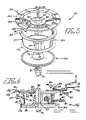
- This embodiment generally comprises a separator assembly 146 having a removably attachable annular spider 148, an annular housing 150, and an annular, lower support cover 152.
- the spider 148 and housing 150 will both preferably be formed by injection molding, and will preferably be formed from a material having a rigid final form, such as Rynite.
- the spider 148 comprises an annular shoulder portion 154 having a plurality of ribs 156 directed radially outwards from its axial center.
- the ribs 156 function to help provide a positive airflow outwardly of the separator 146 to create a labyrinth seal which prevents entry of particulates near the shoulder portion 154.
- the spider 148 also comprises an annular center portion 158 having an elongated, annular, boss portion 160 with an annular opening 162 for receiving the motor shaft 38. Also included are a plurality of vanes 164 extending radially outward from the center portion 158 to the shoulder 154 and angled sufficiently downwardly so as to partially reside within an interior area 166 of the housing 150 when the spider 148 is attached thereto. The vanes 164 operate to help produce the centrifugal force which is needed to separate the coalesced liquid, dust and dirt particulates entrained in the intake air, the process of which will be described in detail below.
- the housing 150 comprises an annular upper flange portion 168, a slightly angled side portion 170, and a rounded, annular bottom portion 172.
- the side portion 170 includes a plurality of elongated, vertically orientated slots 174 (hereinafter "intake slots") which act as intake means to allow liquid, dust and dirt particulates to enter the interior 166 of the separator 146.
- intake slots elongated, vertically orientated slots
- the lower support cover 152 also has a raised, boss portion 176 with an annular opening 178 for receiving the motor shaft 38.
- the lower support cover 152 is of a solid, rigid construction throughout to make it impervious to liquid or solid particulate matter, and is preferably stamped from a mold out of aluminum or a like material which is structurally strong and yet lightweight.
- the boss 89, hexagonal recess 90, and spider nut 83 of FIGS. 2 and 3 have not been illustrated in FIG. 5, nor in the remaining Figures, so as not to unnecessarily complicate the drawings. It should be understood, however, that the embodiment of FIG. 5 and the following embodiments will also preferably incorporate such a boss 89, recess portion 90, and nut 83 to further enhance the ease with which the housings of each of the embodiments may be removed.
- the upper flange portion 168 of the housing 150 also has an annular shoulder portion 180 for resting inside and abutting against a mating annular shoulder portion 182 (not visible in FIG. 5) of the spider 148.
- the housing 150 also has a similar shoulder portion 184 for resting inside and abutting against an annular groove 186 of the lower support cover 152.
- the shoulder and groove portions 182 and 186 of the spider 148 and lower support cover 152 respectively serve to provide support to the housing 150, thereby increasing its structural rigidity to further help it to withstand the centrifugal force applied to it when the separator 146 is in operation, spinning at a high angular velocity.
- the support provided by shoulder portion 182 and groove 186 also allows thinner and lighter materials to be used in the construction of the housing 150, thereby conserving space and weight.
- FIG. 6 also illustrates an annular air deflector flange 188 (not used in the embodiments of FIGS. 2-4) preferably attachable to the blower 18, as illustrated in FIG. 6, or any member near the top of the spider 148.
- the air deflector flange 188 is operable to cover at least a portion of the shoulder portion 154 of the spider 148, and preferably will be of a diameter sufficiently large enough so as to extend outwardly beyond the shoulder portion 154.
- the air deflector flange 188 may be made of a wide variety of materials, but will preferably be stamped from a mold out of a rigid material such as metal or injection molded from a plastic or other similar compound.
- the liquid droplets 126 coalesce as indicated at 128, with the dust and dirt particulates 122 to form a relatively homogeneous mixture of particulates 130.
- the large centrifugal force developed within the separator 146 will then operate to separate, (i.e., centrifuge) the liquid, dust and dirt particulates from the rapidly rotating air mass within the separator 146.
- the coalesced and separated liquid, dust and dirt particulates 130 will then be drawn upwardly and forcibly expelled through a passageway 183, acting as an exhaust means, formed between the shoulder 154 of the spider 148 and the underside of the air deflector flange 188, as indicated by directional arrow 132.
- the exhaust of the coalesced particulates 130 is accomplished by a combination of the suction created by the blower 18, the centrifugal force produced by the housing 150 and the vanes 164 of the spider 148.
- the separated liquid, dust and dirt particulates 130 will then descend into the liquid bath filter 34 (shown in FIG. 1) where they will be trapped therein.
- the depth-to-width ratio of the intake slots 174 of the separator 146 of FIGS. 5 and 6 is also a factor in allowing the proper amount of liquid droplets to enter the separator 146 and for minimizing the drag created on the blower 18 and motor 16 when liquid droplets 126 are allowed to enter the separator 146.
- the depth-to-width ratio is preferably about the same, however, as the depth-to-width ratio of the separator of FIGS. 2-4 (i.e., preferably about two-to-one to three-to-one), as explained in the discussion of FIGS. 2 and 4.
- the outer radius 185 of the shoulder portion 154 of the spider 148 will be about 20% to 60%, and preferably about 40%, greater than the mean outer radius 187 of the vertical side portion 170 of the annular housing 150.
- the outer radius 189 of the fan assembly 19 of the blower 18, in turn, should be about 20% to 60%, and preferably about 40%, greater than the outer radius of the flanged shoulder portion 154 of the spider 148.
- the blower 18 should further be operable to provide a suction-like airflow of about 33 R/s (70 cfm (cubic feet of air per minute)). If the above mentioned ranges are met, adverse affects on the ability of the vacuum system 10 to provide a strong, suction force will be minimized, as will any adverse affects on the air flow through the vacuum system 10. It should also be appreciated that the above ratios will affect the performance of each of the separators disclosed herein, and as such should preferably be met with respect to the other embodiments of the present invention to achieve optimum performance.
- the lower portions of the intake slots of each embodiment of the present invention function to allow liquid droplets to enter the separator.
- this function is dependent on a combination of factors, namely the slot width-to-depth ratio,the rotational speed of the motor assembly 16, and the air movement capacity of the blower 18, which must be considered for each embodiment discussed herein.
- FIG. 8 an alternate embodiment of the present invention is shown generally comprising a separator assembly 190 having an annular spider 192 and an annular, cup-shaped housing 194.
- the spider 192 has a raised, annular, boss center portion 196 integrally formed with a longitudinal base portion 198 and a vertical, annular inner wall 200.
- An annular opening 202 is included in center portion 196 for receiving the motor shaft 38.
- the spider 192 also has a plurality of vanes 204 extending radially outward from the annular inner wall 200 to an annular, flange portion 206.
- the vanes 204 are also angled downward slightly from the flange portion 206 to allow them to reside partially within the housing 194 when the separator 190 is assembled.
- the spider 192 generally operates to provide additional structural support to the housing 194 and to help generate centrifugal force within the housing 194.
- the spider 192 may be manufactured from any suitable rigid material, but will preferably be injection molded from a plastic or similar material, such as Rynite.
- the housing 194 has a side portion 208 having an outer wall 210 and an inner wall 212, and further includes an annular base portion 214 and an internal, vertical sidewall 216.
- the base portion 214 has an annular opening 218 for receiving the motor shaft 38.
- the housing 194 like the spider 192, will preferably be injection molded from a rigid material, such as Rynite.
- the housing 194 will also preferably include an upper flanged portion 220, a bottom portion 222 - (shown most clearly in FIG. 10), and a plurality of vanes 224 bridging the inner wall 212 of the side portion 208 and the internal vertical sidewall 216 for enhancing the radial acceleration of the air mass within the separator 190.
- the vanes 224 could be easily formed with the spider 192 if so desired, as is generally shown in the spider 82 of FIG. 2.
- the vanes 224 will preferably be formed with the spider 192 for the reasons set forth hereinbefore, and the vanes 224 have been shown in FIGS. 8 and 9 formed with the housing 208 to merely illustrate this alternative configuration.
- the housing 194 further includes a plurality of slots 226 (hereinafter “intake slots") disposed in the bottom portion 222 and a plurality of longitudinally oriented elongated apertures 228 circumferentially spaced in the side portion 208 of the separator 190 near the upper flanged portion 220.
- the intake slots 226 extend radially outward from the annular opening 218 in a longitudinal fashion, as can be seen most clearly in FIG. 10, and act primarily as intake means to allow liquid, dust and dirt particulates to enter an interior area 230 of the housing 194. Portions 227 of the intake slots 226 also open onto the side portion 208, and operate to allow the exhaust of a very small amount of particulate matter therethrough.
- the longitudinal exhaust apertures 228 are operable to act as an exhaust means to allow coalesced liquid, dust and dirt particulates within the separator 190 to be centrifugally exhausted therefrom. It should also be mentioned that although only a single row of exhaust apertures 228 has been illustrated in FIGS. 8 and 9, the side portion 208 of the housing 194 could optionally include more than one row of exhaust apertures 228 to further increase the ability of the separator 194 to exhaust particulates therefrom. Furthermore, the exhaust slots need not be longitudinally oriented but instead could be disposed vertically in circumferential fashion around the housing 194. An advantage if the exhaust apertures 228 are disposed in a vertical fashion is that the centrifugal force developed by the separator 194 is sufficient to expel particulates therein even without vanes 224.
- FIG. 8 Also shown in FIG. 8 is an annular support ring 229 affixed to the outer edge 231 of the housing 194. This support ring 229 provides additional structural support to the housing 194, and is essentially similar to the support ring of separator 76.
- annular, lower shoulder 232 of the spider 192 is shown for abuttingly engaging with an inner edge 234 of upper flanged portion 220.
- Shoulder 232 and edge 234 serve to provide a relatively airtight seal to prevent dust and dirt entrained air from entering the separator 190 where the spider 192 and the housing 194 meet and circumvent the operation of the separator 190.
- the exhausted dust and dirt particulates 130 will then descend towards the liquid bath filter 34 and be trapped. A portion of the separated liquid, dust and dirt particulates 130 may be temporarily trapped against the vanes 204 and 224, but will also eventually be exhausted through the exhaust apertures 228 due to the centrifugal force created by the vanes 204 and 224 within the housing 194. The clean air mass 134 left within the separator 190 will then be drawn upwardly out of the separator 190, as indicated by airflow arrow 136, and eventually expelled back into the ambient environment.
- the embodiment of the separator 190 shown in FIGS. 8, 9 and 10 has the added advantage of providing a longer period of time for the liquid, dust and dirt particulates 126 and 122 to coalesce and be separated before they reach the exhaust apertures 228. This is because the liquid, dust and dirt particulates 126 and 122 enter through the bottom portion 222 of the housing 194, and therefore must travel a distance that is longer than that which would be required for the particulates 126 and 122 to travel were they to enter the side portion 208 of the housing 194.
- FIGS. 11 and 12 two variations of the housing 194 of separator 190 can be seen.
- the cup-like housing 236 includes an angled bottom portion 238 with a plurality of elongated slots 240 (hereinafter "intake slots").
- a portion 242 of each intake slot 240 further extends onto a side portion 244 of the housing 236 and each portion 242 tends to perform a small exhaust function to help exhaust coalescing liquid, dust and dirt particulates 130 (shown in FIG. 9).
- the preferred method of construction of the housing 194 is by injection molding, preferably from Rynite.
- FIG. 12 there is shown a modified cup-like housing 246 in accordance with a fifth embodiment of the present invention.
- This housing 246 includes a curved bottom portion 248 with a plurality of elongated intake slots 250. A portion 252 of each intake slot 250 further extends onto a side portion 254 of the housing 246 and also tends to perform a small exhaust function.
- Housing 246 will also preferably be formed by injection molding, preferably from Rynite.
- the angled or curved bottom portions 238 and 248 of housings 236 and 246 respectively may be used to tailor intake characteristics to allow less liquid particulates 126 (shown in FIG. 9) and dust and dirt particulates 122 to enter the separator 190. This serves to decrease the drag of the separator on the motor 16, thereby allowing a less powerful motor to be used.
- FIG. 13 a modified cup-like housing 260 in accordance with a sixth preferred embodiment of the present invention is shown.
- This housing 260 includes a generally flat bottom portion 262 with a plurality of elongated intake-exhaust slots 264.
- the lower portions 266 of each slot 264 perform an intake function while the upper portions 268 of each slot 264 perform an exhaust function in the manner generally described in connection with FIG. 2.
- each ribbed section 270 In between adjacent slots 264 are ribbed portions 270.
- the innermost portions 272 of each ribbed section 270 are further angled to create generally angled edge portions 274.
- Angled edge portions 274 serve to help impede the build-up of dirt and other debris on the interior portions 272 of the ribbed portions 270. This helps to reduce the frequency with which the housing 260 may need to be cleaned.
- each angled edge 274 of ribbed portions 270 can be seen more clearly.
- the angle 276 formed by sides 274a and 274b of each angled edge 274 may vary widely, although an angle of about 60 is preferred.
- FIG. 15 a partial cross-sectional view of an alternative preferred embodiment 278 of the present invention is shown, as it may be incorporated in accordance with section line 15--15 of FIG. 5. Similar to the separator of FIG. 13, adjacent slots 279 of this embodiment 278 form rib sections 280, each of which includes an innermost, angled edge portion 282. Angled edge portions 282 similarly serve to help reduce the build-up of dust and dirt particulates on the inner surfaces of each rib section 280. The angle of each angled portion 282 is also preferably about 60 ° .
- FIG. 16 illustrates a partial cross-sectional view of an alternative preferred embodiment 284 of the present invention, as it may be incorporated in accordance with section line 16--16 of FIG. 10.
- rib portions 286 are formed between adjacent intake slots 287.
- the rib portions 286 each have an angled edge portion 288 on their innermost surface to likewise help reduce dust and dirt particulate build-up thereon.
- the degree of the angle of each angled edge portion 288 is furthermore preferably about 60 ° .
- FIG. 17 a partial cross-sectional view of an alternative preferred embodiment 290 of the present invention is shown, as it may be incorporated in accordance with section line 17--17 of FIG. 11. Between adjacent slots 292 are formed rib portions 294. The innermost portion of each rib portion 294 further includes an angled edge portion 296 having an angle of preferably about 60 °.
- Rib portions 300 are formed between adjacent intake slots 302.
- the innermost portion of each rib portion 300 further includes an angled edge portion 304 having an angle of preferably about 600.
- the angled edge portions 296 and 304 of FIGS. 17 and 18 serve to help reduce the build-up of dust and dirt particulates on the innermost surfaces of rib portions 294 and 300 respectively.
- the present invention is thus well calculated to provide a low cost, easily manufactured means for allowing liquid particulates to coalesce with dust and dirt particulates entrained in intake air to thereby improve the centrifuging ability of the separator of a vacuum system. Consequently, a greater number of particulate contaminants may be removed from contaminated intake air, which contaminants would have otherwise been redeposited by other vacuum cleaner systems back into the ambient environment.
Landscapes
- Engineering & Computer Science (AREA)
- Mechanical Engineering (AREA)
- Filters For Electric Vacuum Cleaners (AREA)
- Centrifugal Separators (AREA)
- Separating Particles In Gases By Inertia (AREA)
- Other Liquid Machine Or Engine Such As Wave Power Use (AREA)
- Refuse Collection And Transfer (AREA)
- Filtering Of Dispersed Particles In Gases (AREA)
- Separation By Low-Temperature Treatments (AREA)
- Separation Using Semi-Permeable Membranes (AREA)
Abstract
Description
- This invention relates to vacuum cleaning devices and, more particularly, to an improved separator for use in conjunction with liquid bath type vacuum cleaners.
- Vacuum cleaners of various designs are used in residential and commercial settings for cleaning purposes. These appliances develop suction to create airflow which picks up large and small dust particulates from a surface being cleaned. These particulates are then separated from the air within the vacuum cleaner for later disposal.
- One type of vacuum cleaner is a canister type which has a relatively stationary canister which is connected to a moveable wand by a flexible connecting hose. One particular design of canister type vacuum cleaners is known as a liquid bath type. This type of vacuum cleaner directs incoming air and particulates into contact with a liquid bath which is typically water, which in turn absorbs particulate matter. Liquid bath type cleaners in general have a significant advantage in that their filtration mechanism uses readily available water, thereby eliminating the need for replaceable filters. In addition, these machines provide a room humidifying effect since some of the water in the liquid bath becomes dissolved in the air discharged from the vacuum cleaner during use.
- Numerous designs of liquid bath type vacuum cleaners are presently known. The following U.S. Patents, the disclosures of which are hereby incorporated by reference, and all of which are assigned to the assignee of the present invention, relate to various improvements in liquid bath type vacuum cleaner: Nos. 2,102,353; 2,221,572; 2,886,127; and 2,945,553.
- Although devices constructed in accordance with the above mentioned issued patents perform satisfactorily, designers are constantly seeking to reduce the amount of fine dust and dirt particulates that escape entrapment in the liquid bath type filter and which are expelled by the vacuum cleaner back into the ambient environment. In this regard, designers have been striving to improve the operation of a part of such vacuum cleaners which is generally known as the separator. Up until the present, the separator of a vacuum cleaner has functioned to provide a first stage of filtration by impeding the flow of medium and large size dust and dirt particles, which have not been trapped in the liquid bath, through the vacuum cleaner and back into the ambient environment.
- The efficacy of the separator could be further enhanced, however, if the separator was operable to provide a second stage of filtration to remove the fine dust and dirt particulates which enter it, and which would otherwise normally be exhausted into the ambient environment. One method of accomplishing this would be by employing a method of separation known generally as centrifugation. Briefly, centrifugation involves the application of centrifugal force to an air mass entrained with liquid or solid particulate matter. The centrifugal force is typically produced by drawing the contaminated air mass into an annular chamber and spinning the chamber and contaminated air mass therein radially at a high angular velocity. The magnitude of centrifugal force created, which may be on the order of 10,000 Gs or more depending on the angular velocity of the chamber, forces the liquid and the contaminants, i.e., dust and dirt particulates, radially outward toward the outer wall of the chamber where they are exhausted through openings in the chamber wall, thereby leaving a clean air mass within the rotating chamber. If applied to a separator of a vacuum cleaner, centrifugation could be used to help filter out the smaller dust and dirt particulates which would otherwise pass through the vacuum cleaner and back into the ambient environment.
- To still further enhance the filtering of small dust and dirt particles which have escaped being trapped in the liquid bath filter and which have entered the separator, it has been found that if microscopic liquid particulates, or droplets, from the liquid bath are also drawn into the separator and allowed to coalesce with the dust and dirt particulates entrained in the intake air, a marked improvement will occur in the amount of dust and dirt particulates removed by the separator. It has further been found that this improvement can be achieved with negligible adverse effects on other aspects of the vacuum system, such as the suction-like air flow through the system.
- In view of the foregoing, it is a principal object of the present invention to provide an improved separator for a vacuum cleaner for more effectively separating fine dust and dirt particulates entrained in intake air from the intake air.
- It is a further object of the present invention to provide an improved separator operable to centrifuge small dust and dirt particulate matter from intake air before the intake air is expelled back into the ambient environment.
- It is still a further object of the present invention to provide an improved separator operable to allow liquid particulates to be drawn therein and coalesce with fine dust and dirt particulates entrained in intake air.
- It is yet another object of the present invention to provide an improved separator operable to remove coalescing liquid, dust and dirt particulates from within the separator, thereby producing a clean air mass which may be expelled back into the ambient environment.
- It is still another object of the present invention to provide an improved separator capable of removing coalescing liquid, dust and dirt particulates entrained in intaked air, which produces only negligible adverse effects on the suction-like force of, and airflow through, a vacuum system.
- According to the present invention there is provided a separator for a liquid bath-type air filtration device for separating liquid droplets coalescing with dust and dirt particulates entrained in ingested air through an application of centrifugal force to the ingested air, said separator comprising:
- annular housing means operable to rotate axially about a vertical axis for generating a centrifugal force to be applied to the ingested air;
- intake means operatively associated with said annular housing means for enabling dust and dirt particulates entrained in ingested air to be drawn into an interior area of said annular housing means, and for enabling liquid droplets from a liquid source entrained in the ingested air to be drawn into said interior area of said annular housing means to thereby enable the dust and dirt particulates and the liquid droplets to coalesce therein, whereby to subject the coalescing liquid droplets and dust and dirt particulates to centrifugal force and to thereby separate them from the ingested air; and
- exhaust means operatively associated with said annular housing means for enabling the coalescing liquid droplets and dust and dirt particulates within said interior area of said annular housing means to be expelled therefrom as the coalescing liquid droplets and dust and dirt particulates are forced radially outward by centrifugal force towards and through said exhaust means by rapid, axial rotation of said annular housing means.
- In a first preferred embodiment, the separator comprises annular, cup-like housing means adapted to rotate axially about its vertical axis for generating centrifugal force to be applied to liquid, dust and dirt particulates entrained in the intake air; intake means for allowing air containing dust and dirt particulates along with microscopic liquid particulates to enter an interior area of the housing means and coalesce; and exhaust means for allowing the coalescing particulates to be expelled from the interior area of the housing means as they are centrifuged towards and through the exhaust means during rapid, axial rotation of the housing means.
- In a second preferred embodiment the separator includes annular housing means adapted to rotate axially for generating centrifugal force to be applied to the intake liquid and the air containing dust and dirt particulates; intake means for allowing the liquid and the air containing dust and dirt particulates to enter the annular housing means and coalesce therein; exhaust means for allowing the coalescing particulates to be expelled from the annular housing means; and a removable lower support cover for providing additional structural support to the annular housing means and for blocking the intake of the liquid and the air containing dust and dirt particulates through a lower portion of the annular housing means.
- In a third preferred embodiment the separator comprises an annular, cup-like housing means having intake means disposed on a bottom portion of the cup-like housing means. The intake means is operable to allow the liquid and the dust and dirt particulates entrained in air intaked into the cup-like housing means to coalesce therein. The cup-like housing means operates through centrifugal force developed by axial rotation about its vertical axis to force the particulates outwardly through exhaust means disposed on a side portion of the cup-like housing means.
- In a fourth preferred embodiment the separator includes a cup-like housing means having an angled bottom portion for increasing the centrifugal force therein, and an intake means disposed on the angled bottom portion for allowing the liquid and the air containing the dust and dirt particulates to be passed into the cup-like housing means. The angled bottom portion further helps to control the amount of particulates intaked into the separator.
- A fifth preferred embodiment includes a cup-like housing means having a curved bottom portion with intake means disposed on the curved bottom portion. The curved bottom portion also helps to control the amount of particulates intaked into the cup-like housing means.
- In each of the above embodiments, a spider having a plurality of vanes may be incorporated. The spider may be removably attached to the housing means and provides additional structural support thereto. The spider also helps to increase the centrifugal force applied to the liquid and the air containing dust and dirt particulates intaked into the housing means and to provide a labyrinth seal with the separator to prevent dust and dirt particulates from entering the area between the separator and the spider, and thereby circumventing the operation of the intake means.
- The various advantages of the present invention will become apparent to one skilled in the art upon reading the following specification and subjoined claims, and by reference to the drawings in which:
- FIG. 1 is a vertical sectional view partially fragmented of a vacuum cleaner within which the separator may be used, including a partially fragmented side elevational view of the separator showing it as it may be typically connected therein;
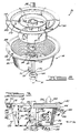
- FIG. 2 is an exploded perspective view of a first preferred embodiment of the present invention showing the spider, the cup-like housing, the intake/exhaust slots in the cup-like housing, a portion of a motor shaft for providing axial rotation of the spider and the cup-like housing, and the motorshaft nut;
- FIG. 3 is a side elevational view partially in cross-section of the preferred embodiment of the separator and the spider in assembled form;
- FIG. 4 is a cross-sectional plan view along direction lines 4-4 of FIG. 3;
- FIG. 5 is an exploded perspective view of a second preferred embodiment of the separator showing a housing, a spider, and a lower support cover;
- FIG. 6 is a side elevational view partially in cross-section of the separator of FIG. 5 and a partial side cross-sectional view of an air deflector flange;
- FIG. 7 is an exploded schematic side view of the spider and the housing of FIGS. 5 and 6, a portion of the blower of FIG. 1 and its internal fan blades indicating the various relative outer diameters of each which influence the operation of the separator;
- FIG. 8 is an exploded perspective view of a third preferred embodiment of the present invention showing an annular, cup-like housing and a spider;
- FIG. 9 is a side elevational view partially in cross-section of the separator of FIG. 8;
- FIG. 10 is a bottom elevational view of the separator of FIGS. 8 and 9 showing more clearly the bottom portion of the cup-like housing and the intake slots therein;
- FIG. 11 is a side elevational view of a cup-like housing having an angled bottom portion, in accordance with a fourth preferred embodiment of the present invention;
- FIG. 12 is a side elevational view of a cup-like housing having a curved bottom portion, in accordance with a fifth preferred embodiment of the present invention;
- FIG. 13 is a perspective view of a sixth preferred embodiment of the present invention showing an annular, cup-like housing having ribbed portions with angles formed on their internal vertical edges;
- FIG. 14 is a cross-sectional view of the housing of FIG. 13 taken along
section line 14--14 of FIG. 13; - FIG. 15 is a cross-sectional view of the angled edge portions of an alternative preferred embodiment of the present invention, as they may be incorporated in accordance with
section line 15--15 of FIG. 5; - FIG. 16 is a cross-sectional view of the angled edge portions of an alternative preferred embodiment of the present invention, as they may be incorporated in accordance with
section line 16--16 of FIG. 10; - FIG. 17 is a cross-sectional view of the angled edge portions of an alternative preferred embodiment of the present invention, as they may be incorporated in accordance with
section line 17--17 of FIG. 11; and - FIG. 18 is a cross-sectional view of the angled edge portions of an alternative preferred embodiment of the present invention, as they may be incorporated in accordance with
section line 18--18 of FIG. 12; - In FIG. 1, there is shown a vertical sectional partially fragmented view of a typical
vacuum cleaner system 10 in which aseparator 12 of the present invention, as is also shown in a partially fragmented side elevational view, may be used. Thevacuum cleaner 10 principally comprises ahousing assembly 14, amotor assembly 16, ablower assembly 18, and aseparator 12. - The
housing assembly 14 includes alower water pan 20, acap 22 and acap cover 24. Preferably, thehousing assembly 14 is easily removable from thewater pan 20 to enable the convenient removal and replacement of liquid therein. Themotor assembly 16 and theblower assembly 18 are generally centrally supported within thehousing assembly 14. Themotor assembly 16 and theblower assembly 18 are supported within thehousing assembly 14 by providing a pair of ring-shapedsupport members - A
vacuum hose 30 is also shown attached to aninlet port 32. Theinlet port 32 opens into alower chamber area 33 wherein a water or other liquid-type bath 34 is contained in thelower water pan 20. - The
motor assembly 16 provides motive power for operation of afan assembly 19 of theblower assembly 18. Themotor assembly 16 includes a centralrotating armature 36 encircling and connected to amotor shaft 38, which extends downwardly into theblower assembly 18. Surrounding thearmature assembly 36 is afield assembly 40. A combination bearing retainer and brush holder 42 is provided which retains anupper bearing assembly 44 and supports a pair ofbrushes 46 which communicate electrical energy to thearmature 36 through acommutator 48. Themotor assembly 16 is of the type generally known as a universal motor which has the desirable operating characteristics for use in conjunction with vacuum cleaners. - An axial
flow motor fan 50 is attached to the upper portion of themotor shaft 38 and generates air flow for cooling themotor assembly 16. Thefield assembly 40 and the bearing retainer and brush holder 42 are fixed through attachment to a motor base 52 by using threadedfasteners 54. The motor base 52 is in turn connected to aweb 56 by employing aclamping ring 58. The direction of air flow past themotor assembly 16 generated by thefan 50 is controlled by providing a baffle 60 which generally encircles and encloses themotor assembly 16. The motor base 52 further defines a bearingretainer pocket 62 which receives amiddle bearing assembly 64, which is secured by a push- in type clip 66. - The
separator 12 itself is removably attached at a lower, threaded end 68 of themotor shaft 38 by anacorn nut 70. Theseparator 12 further includes a plurality ofslots 72 for allowing intake air to be drawn and aremovable spider 73 to provide additional structural support to theseparator 12 and to help generate centrifugal force within theseparator 12. - In operation, the
motor 16 of thevacuum cleaner 10 operates to provide a motive force to themotor shaft 38 to rotate thefan assembly 19 of theblower 18 and theseparator 12 rapidly about a central axis. Theblower 18 operates to create a strong, suction force (vacuum) to draw air entrained with dust and dirt particulates in through thevacuum hose 30 and theinlet port 32 and into contact with theliquid bath filter 34. Theliquid bath filter 34, which may employ one or more of a variety of liquid agents but preferably comprises water, operates to trap the majority of dust and dirt particulates intaked intolower chamber 33. The remaining dust and dirt particulates, which will be mostly microscopic in size, will be drawn by theblower 18 up into theseparator 12 through theslots 72. - The
separator 12 operates to separate the dust and dirt particulates from the intaked air by centrifugal force (i.e., "centrifugation") generated as a result of its rapid, axial rotation. The centrifugal force also operates to forcibly exhaust the particulates outwardly from theseparator 12. Eventually, many of the dust and dirt particulates that initially escaped entrapment in theliquid bath filter 34 will be trapped therein, and the particulates which are not will be drawn upwardly again into theseparator 12 for further separation. The clean air mass within theseparator 12, which will exist after the dust and dirt particulates are removed, will then be drawn upwardly through theblower 18 and expelled into the ambient environment throughair chamber 74. - The foregoing has been intended as a general description only of the internal operation of a vacuum cleaner in which the present invention may be used. More specific details of the operation of liquid bath vacuum cleaners may be obtained by referring to the previously identified U.S. patents, including US-A-4 693 734, Figure 1, of which shows a liquid bath-type air filtration device of generally similar construction to that shown in Figure 1 of the present application, except in relation to the
separator 12. - With reference to FIG. 2, an exploded perspective view of a
separator assembly 76 in accordance with the present invention is shown. Theseparator 76 generally comprises an annular, cup-like housing 78 removably attachable bynut 70 to themotor shaft 38 and adapted to rotate coaxially with themotor shaft 38. Thenut 70 preferably has a chamferedend 80 for helping to maintain the concentricity of theseparator 76 with themotor shaft 38. A spider 82, removably attachable to thehousing 78, matingly engages thehousing 78 to provide additional structural support to thehousing 78 and to provide radial acceleration to an air mass within theseparator 76. The spider 82 is secured to the shaft by ahexagonal nut 83. - The
housing 78 may be made from virtually any rigid material, but preferably will be injection molded from "Rynite", a glass filled polyester compound commercially available from the DuPont Corporation. This compound is particularly desirable due to its relatively light weight and high strength characteristics. - The
housing 78 comprises a longitudinal, upperflanged portion 84; a slightlyconical side portion 86; alongitudinal bottom portion 88 having an integrally formedboss portion 89 with a hexagonal shaped recess 90, thebottom portion 88 further having anannular opening 91 for receiving themotor shaft 38; and a plurality of vertically oriented, elongated slots 92 (hereinafter "intake/exhaust slots") circumferentially disposed uniformly around theside portion 86 for acting as a combination of intake and exhaust means. The intake/exhaust slots 92 also-define a plurality of circumferentially spacedrib portions 93. The intake/exhaust slots 92 further have upper andlower portions lower portion 96 of eachslot 92 operable to act as an intake means and theupper portion 94 of eachslot 92 operable to act as an exhaust means. The functions of the upper andlower portions flanged portion 84,vertical side portion 86, and thebottom portion 88 form an integral, one-piece structure. - The hexagonal recess 90 of
boss portion 89 is adapted to fit over thehexagonal nut 83 when thehousing 78 is matingly engaged with the spider 82. This feature helps facilitate removal of thenut 70, which may on occasion become corroded to theshaft 38, when thehousing 78 is to be removed for cleaning. By providing the hexagonal-shaped recess 90, thehousing 78 may be gripped when turning thenut 70, and will help to hold theshaft 38 stationary via its form-fitting coupling over thehexagonal nut 83, while turning thenut 70. It should be understood that a variety of shapes for the recess 90 could be used in lieu of a hexagonal shape, as long as thenut 83 is shaped similar to the recess 90. - The
housing 78 also includes asupport ring 98 affixed to anouter edge 100 of the upperflanged portion 84. Thesupport ring 98 will preferably be made from a rigid, lightweight material such as aluminum, and may be rolled ontoouter edge 100 by any machine suitable to rotate thehousing 78 360 degrees about its vertical axis while form fitting thesupport ring 98 to theouter edge 100 of the upperflanged portion 84. Thesupport ring 98 serves to provide even further additional structural support to thehousing 78 to help it withstand the large centrifugal force exerted on it during operation of theseparator 76. - The spider 82, which is preferably injection molded from a rigid material such as Rynite, comprises an
annular shoulder portion 102, a raisedboss portion 104 having anannular opening 106 coaxial with the opening 90 in thehousing 78 for receiving themotorshaft 38, and an inner, vertical,annular portion 108 disposed coaxially with the raisedboss portion 104. The spider 82 also includes a substantiallyflat base portion 110 for connecting theboss portion 104 to verticalannular portion 108. Further included are a plurality of elongated, outwardly and downwardly protrudingvanes 112 disposed circumferentially around theannular shoulder portion 102. Thevanes 112 connect theannular shoulder portion 102 with the verticalannular portion 108, and a portion of eachvane 112 extends over the upper surface of theshoulder portion 102 to the outer edge of theshoulder portion 102 to form a plurality ofrib sections 114. Therib sections 114 operate to generate a positive airflow outwardly from theseparator 76 to create a "labyrinth seal" between the upper surface of theshoulder portion 102 and the lower surface of theblower 18 which prevents particulates from entering the separator at that point and circumventing the operation of theseparator 76. - The
vanes 112 are adapted to reside in nesta- ble fashion primarily within theside portion 86 of the cup-like housing 78, and have anglededges 116 which will be resting in abutting contact with inside portions of theside portion 86 of thehousing 78 when the spider 82 is attached to the housing 78 (as is shown most clearly in FIG. 3). Thevanes 112 are also preferably spaced apart from each other in a uniform fashion. Together, theannular shoulder portion 102, thevanes 112, the verticalannular portion 108, thebase portion 110 and theboss portion 104 comprise an integrally formed, single piece structure. It should be understood, however, that thevanes 112 of the spider could instead be integrally formed with thehousing 78, as has been illustrated in subsequent figures herein. Integrally forming thevanes 112 with the spider 82, however, allows the interior surfaces of thehousing 78 and thevanes 112 to be periodically cleaned more easily and effectively. Also, forming thevanes 112 integrally with the spider 82 rather than with thehousing 78 enhances the ease with which thehousing 78 may be manufactured. - In FIG. 3, the
separator 76 of FIG. 2 is illustrated showing the spider 82 andhousing 78 in an assembled state. The spider 82 includes an annular,lower shoulder portion 118 adapted to rest nestably within amating shoulder portion 120 of thehousing 78. Together, theshoulder portions - Turning now to the specific operation of the
separator 76, from FIG. 3 it can be seen that fine dust and dirt particulates, represented by the shadedcircles 122, entrained in theintake air 124, which have not been trapped by liquid bath filter 34 (shown in FIG. 1), are drawn into the cup-like housing 78 through thelower portions 96 of each intake/exhaust slot 92, which operate initially as intake means. In addition, liquid particulates, or droplets, represented byunshaded circles 126, having diameters of about 2-10 microns are also drawn in from theliquid bath filter 34 through thelower portion 96 of each intake/exhaust slot 92. This is due in part (1) to the unique configuration of the intake/exhaust slots 92, which will be discussed further below, (2) in part to the vacuum-like force created by the blower 18 (shown in FIG. 1), and (3) in part to the rapidly axially rotatingvanes 112 of the spider 82, all of which will typically be rotating together at preferably about 10,000-15,000 rpm to produce a force of about 10,000-15,000 Gs. Large liquid, dust and dirt droplets, i.e., droplets having a diameter greater than about 10 microns, will be restricted by theseparator 76 from entering its internal area due primarily to the size and configuration of the intake/exhaust slots 92, and due also to the high centrifugal force imparted on the air mass in the near vicinity of the separator by the by the intake/exhaust slots 92 and theribs 93. - A portion of the liquid droplets larger than about 10 microns in diameter will also be broken down into droplets having diameters within the range of about 2 to 10 microns when they collide with the rapidly rotating
ribs 93 of thehousing 78 as they attempt to pass through the intake/exhaust slots 92. Once inside thehousing 78, theliquid droplets 126 form a "fog-like" arrangement of fineliquid droplets 126. As they move toward theboss portion 89 at the axial center of thehousing 78, the spacing between theliquid droplets 126 is substantially reduced, which increases the probability of collisions between them and the dust anddirt particulates 122. - As the dust and dirt particulate-entrained
air 124 and theliquid droplets 126 collide inside the interior area of thehousing 78, they will then coalesce, as shown at 128. This is due in large part to the rapidly rotating nature of the air mass within thehousing 78. As the dust anddirt particulates 122 and thewater droplets 126 coalesce, their mass to surface area ratio increases. This causes them to precipitate toward theside portion 86 of thehousing 78 in response to the centrifugal force generated within thehousing 78. During this coalescing process some of theliquid droplets 126 will combine with each other, thus simulating the process of rain formation in nature. As the coalescing particulates, represented by partially shadedcircles 130, are drawn upwardly by the suction force of theblower 18 and forced outwardly by the centrifugal force generated within thehousing 78, they will pass through theupper portions 94 of the intake/exhaust slots 92 as indicated byairflow arrow 132. The coalescingparticulates 130 are forced outwardly towards theside portion 86 of the housing largely because of the increased centrifugal force experienced by them as they move upwardly toward the upperflanged portion 84 of thehousing 78. The increased centrifugal force near the upperflanged portion 84, as opposed to thebottom portion 88 of thehousing 78, results because of the larger diameter of thehousing 78 near the upperflanged portion 84. A portion of the coalesced liquid, dust anddirt particulates 130 may also be temporarily trapped by the rotatingvanes 112 of the spider 82 but will also eventually be exhausted through theupper portions 94 of the intake/exhaust slots 92 by the centrifugal force created by thevanes 112. - After being exhausted from the
housing 78, most of the coalesced liquid, dust anddirt particulates 130 will descend into the liquid bath filter 34 (shown in FIG. 1) where they will be trapped therein. The remainder ofexhausted particulates 130 will descend along the inside surface of thewater pan 20 and portions of surfaces defining the inlet port 32 (both shown in FIG. 1), and will also eventually be trapped in theliquid bath filter 34, or will be re-intaked into theseparator 76 for further separation. Aclean air mass 134 will then be left within theseparator 76, which will then be drawn upwardly by blower 18 (shown in FIG. 1) out of the interior area of theseparator 76, as indicated byairflow arrow 136, and eventually expelled into the ambient environment. - The
separator 76 thus functions to actually provide first and second stages of separation: first, restricting the access of large particulates and second, separating the smaller particulates which are allowed to enter its interior area from the intaked air. - The relatively air-tight seal created by
mating shoulder portions separator 76. This seal will prevent any expelled liquid, dust anddirt particulates 130 from reentering theseparator 76 where the spider 82 andhousing 78 meet, thereby circumventing the air filtration operation of theseparator 76. Also, therib sections 114 of the spider 82 will help to prevent dust and dirt entrained air from entering theseparator 76 by creating a secondary airflow directed outwardly from theseparator 76. - Several additional factors also cooperate to permit the intake of liquid particulates through the
lower portions 96 of the intake/exhaust slots 92, and the exhaust of the particulates through theupper portions 94. First, theangle 138 of theside portion 86 from an imaginaryvertical line 140 orthogonal toflanged portion 84 has been found to be one factor that influences the intake ofliquid droplets 126. If thisangle 138 is within the range of about 5 ° to 20°, and preferably about 10 ° to 12°, thelower portions 96 of the intake/exhaust slots 92 will tend to act as intakes to allow entry ofliquid droplets 126 having diameters of about 2 to 10 microns. - Another factor is the length of the intake/
exhaust slots 92. The length of each intake/exhaust slot 92 will preferably be maximized so that eachslot 92 extends along almost the entirevertical side portion 86. This further helps enable thelower portions 96 to act as an intake means and theupper portions 94 to act as exhaust means. - Referring now to FIG. 4, another factor in the performance of the
separator 76, the intake/exhaust slot depth-to-width ratio, will be explained. In order for the intake/exhaust slots 92 to function properly as both an intake and exhaust means, thedepth 142 of eachslot 92 should preferably be about two to three times as great as the width 144 of each intake/exhaust slot 92. Thedepth 142 of each intake/exhaust slot 92 will be preferably about 3.1 to 4.6 mm (0.120 to 0.180 inches), while the width of eachslot 92 will be preferably about 1 to 1.5 mm (0.040 to 0.060 inches). If this two-to-one to three-to-one ratio is maintained, the intake/exhaust slots 92 will function to allow entry and exhaust of liquid, dust and dirt particulate entrained air while minimizing the loss of suction-like force provided by theblower 18 and the degradation of airflow through thevacuum system 10. - The overall ability of the
separator 76 to remove liquid, dust and dirt particulate entrained air will also depend on the number of intake/exhaust slots 92 included in thehousing 78. Preferably the number of intake/exhaust slots 92 should be maximized. It has been found, however, that if the total number of intake/exhaust slots 92 is between about 40 to 110, and preferably between 70 to 80, with the slot width-to-depth ratio being preferably about two or three to one as described above, a desirable balance will be achieved between maximizing the separating ability of theseparator 76 and maintaining the structural strength of thehousing 78. - Drawing liquid droplets into the
separator 76 and allowing them to coalesce with the dust and dirt particulates entrained in the intake air serves to significantly increase the centrifugation of the dust and dirt particulates from the intake air. This activity has further been found to improve the amount of dust and dirt particulates removed by theseparator 76 from the intaked air by up to 50% for certain types of particulate matter. More specifically, improvements in the number of fine dust particulates (i.e., particulates having diameters of 0.3 to 10.0 microns) removed from the intake air over a 30 second period range from about 19% to 57%. Improvements in the removal of fused alumina particulates having diameters of about 0.3 to 10.0 microns have also been found to range from about 16% to 79% for various particulate sizes when tested over a 30 second period. Improvements in the removal of calcinated aluminum oxide particulates and ambient air particulates of similar diameters and for a similar time period have also been found to range up to 85% for some calcinated aluminum oxide particulates, with the mean increases for calcinated aluminum oxide particulates and ambient air particulates being approximately 40% and 15% respectively. - Increasing the diameter significantly can result in a marked reduction of airflow through the system. A significantly larger diameter separator would also likely introduce additional vibration problems. Increasing the angular velocity significantly would likely increase the stress on the various components of the separator beyond acceptable levels. Using a liquid agent to provide liquid droplets and drawing the liquid droplets into the separator thus allows a smaller diameter separator to be used. This also allows the separator to be driven at a lower angular velocity, thereby avoiding the structural strength problems which would otherwise likely be incurred if liquid droplets were not used in the system.
- Referring now to FIG. 5, a second preferred embodiment of the present invention is shown. This embodiment generally comprises a
separator assembly 146 having a removably attachableannular spider 148, anannular housing 150, and an annular,lower support cover 152. Thespider 148 andhousing 150 will both preferably be formed by injection molding, and will preferably be formed from a material having a rigid final form, such as Rynite. - The
spider 148 comprises anannular shoulder portion 154 having a plurality ofribs 156 directed radially outwards from its axial center. Theribs 156 function to help provide a positive airflow outwardly of theseparator 146 to create a labyrinth seal which prevents entry of particulates near theshoulder portion 154. - The
spider 148 also comprises anannular center portion 158 having an elongated, annular,boss portion 160 with anannular opening 162 for receiving themotor shaft 38. Also included are a plurality ofvanes 164 extending radially outward from thecenter portion 158 to theshoulder 154 and angled sufficiently downwardly so as to partially reside within aninterior area 166 of thehousing 150 when thespider 148 is attached thereto. Thevanes 164 operate to help produce the centrifugal force which is needed to separate the coalesced liquid, dust and dirt particulates entrained in the intake air, the process of which will be described in detail below. - The
housing 150 comprises an annularupper flange portion 168, a slightlyangled side portion 170, and a rounded,annular bottom portion 172. Theside portion 170 includes a plurality of elongated, vertically orientated slots 174 (hereinafter "intake slots") which act as intake means to allow liquid, dust and dirt particulates to enter theinterior 166 of theseparator 146. For simplicity, thesupport ring 98 ofseparator 76 has not been illustrated in FIGS. 5 and 6, although it should be understood that thering 98 may be so incorporated to provide further structural strength to thehousing 150. - The
lower support cover 152 also has a raised,boss portion 176 with anannular opening 178 for receiving themotor shaft 38. Thelower support cover 152 is of a solid, rigid construction throughout to make it impervious to liquid or solid particulate matter, and is preferably stamped from a mold out of aluminum or a like material which is structurally strong and yet lightweight. Theboss 89, hexagonal recess 90, andspider nut 83 of FIGS. 2 and 3 have not been illustrated in FIG. 5, nor in the remaining Figures, so as not to unnecessarily complicate the drawings. It should be understood, however, that the embodiment of FIG. 5 and the following embodiments will also preferably incorporate such aboss 89, recess portion 90, andnut 83 to further enhance the ease with which the housings of each of the embodiments may be removed. - Referring now to FIG. 6, the
upper flange portion 168 of thehousing 150 also has anannular shoulder portion 180 for resting inside and abutting against a mating annular shoulder portion 182 (not visible in FIG. 5) of thespider 148. Thehousing 150 also has asimilar shoulder portion 184 for resting inside and abutting against anannular groove 186 of thelower support cover 152. The shoulder andgroove portions spider 148 andlower support cover 152 respectively serve to provide support to thehousing 150, thereby increasing its structural rigidity to further help it to withstand the centrifugal force applied to it when theseparator 146 is in operation, spinning at a high angular velocity. The support provided byshoulder portion 182 and groove 186 also allows thinner and lighter materials to be used in the construction of thehousing 150, thereby conserving space and weight. - Initially, it should be mentioned that FIG. 6 also illustrates an annular air deflector flange 188 (not used in the embodiments of FIGS. 2-4) preferably attachable to the
blower 18, as illustrated in FIG. 6, or any member near the top of thespider 148. Theair deflector flange 188 is operable to cover at least a portion of theshoulder portion 154 of thespider 148, and preferably will be of a diameter sufficiently large enough so as to extend outwardly beyond theshoulder portion 154. Theair deflector flange 188 may be made of a wide variety of materials, but will preferably be stamped from a mold out of a rigid material such as metal or injection molded from a plastic or other similar compound. - Returning to the operation of the
separator 146 of FIG. 6, dust and dirt particulate entrained air enters theintake slots 174 from lower chamber area 33 (shown in FIG. 1), as indicated by the small,shaded circles 122 withinairflow arrow 124. Liquid droplets from the liquid bath filter 34 (shown in FIG. 1) are also drawn in through theintake slots 174, as indicated by small,unshaded circles 126, by the configuration of theintake slots 174, the suction force created by theblower 18, the rapidly, axially rotatingannular housing 150 and thespider 148. Once inside theinterior area 166 of theannular housing 150, theliquid droplets 126 coalesce as indicated at 128, with the dust anddirt particulates 122 to form a relatively homogeneous mixture ofparticulates 130. The large centrifugal force developed within theseparator 146 will then operate to separate, (i.e., centrifuge) the liquid, dust and dirt particulates from the rapidly rotating air mass within theseparator 146. - The coalesced and separated liquid, dust and
dirt particulates 130 will then be drawn upwardly and forcibly expelled through a passageway 183, acting as an exhaust means, formed between theshoulder 154 of thespider 148 and the underside of theair deflector flange 188, as indicated bydirectional arrow 132. The exhaust of the coalescedparticulates 130 is accomplished by a combination of the suction created by theblower 18, the centrifugal force produced by thehousing 150 and thevanes 164 of thespider 148. The separated liquid, dust anddirt particulates 130 will then descend into the liquid bath filter 34 (shown in FIG. 1) where they will be trapped therein. Theclean air mass 134 left within theseparator 146 after the coalesced liquid, dust anddirt particulates 130 have been exhausted will then be drawn upwardly by theblower 18, as indicated byairflow arrow 136, through thevacuum system 10 and eventually expelled back into the ambient environment. - As with the preferred embodiment discussed in connection with FIGS. 2, 3 and 4, the depth-to-width ratio of the
intake slots 174 of theseparator 146 of FIGS. 5 and 6 is also a factor in allowing the proper amount of liquid droplets to enter theseparator 146 and for minimizing the drag created on theblower 18 andmotor 16 whenliquid droplets 126 are allowed to enter theseparator 146. The depth-to-width ratio is preferably about the same, however, as the depth-to-width ratio of the separator of FIGS. 2-4 (i.e., preferably about two-to-one to three-to-one), as explained in the discussion of FIGS. 2 and 4. - Still another factor that affects the performance of the
separator 146 is the relative outer diameters of thefan assembly 19 of theblower 18, theflanged shoulder portion 154 of thespider 148, and thehousing 150. Referring now to FIG. 7, for optimum performance, i.e., that point where liquid droplets just begin to enter theintake slots 174, theouter radius 185 of theshoulder portion 154 of thespider 148 will be about 20% to 60%, and preferably about 40%, greater than the mean outer radius 187 of thevertical side portion 170 of theannular housing 150. Theouter radius 189 of thefan assembly 19 of theblower 18, in turn, should be about 20% to 60%, and preferably about 40%, greater than the outer radius of theflanged shoulder portion 154 of thespider 148. Theblower 18 should further be operable to provide a suction-like airflow of about 33 R/s (70 cfm (cubic feet of air per minute)). If the above mentioned ranges are met, adverse affects on the ability of thevacuum system 10 to provide a strong, suction force will be minimized, as will any adverse affects on the air flow through thevacuum system 10. It should also be appreciated that the above ratios will affect the performance of each of the separators disclosed herein, and as such should preferably be met with respect to the other embodiments of the present invention to achieve optimum performance. - It is thus a key aspect of the present invention that the lower portions of the intake slots of each embodiment of the present invention function to allow liquid droplets to enter the separator. As can be seen, this function is dependent on a combination of factors, namely the slot width-to-depth ratio,the rotational speed of the
motor assembly 16, and the air movement capacity of theblower 18, which must be considered for each embodiment discussed herein. - Referring now to FIG. 8, an alternate embodiment of the present invention is shown generally comprising a
separator assembly 190 having anannular spider 192 and an annular, cup-shapedhousing 194. Thespider 192 has a raised, annular, boss center portion 196 integrally formed with a longitudinal base portion 198 and a vertical, annularinner wall 200. An annular opening 202 is included in center portion 196 for receiving themotor shaft 38. Thespider 192 also has a plurality ofvanes 204 extending radially outward from the annularinner wall 200 to an annular,flange portion 206. Thevanes 204 are also angled downward slightly from theflange portion 206 to allow them to reside partially within thehousing 194 when theseparator 190 is assembled. Thespider 192 generally operates to provide additional structural support to thehousing 194 and to help generate centrifugal force within thehousing 194. Thespider 192 may be manufactured from any suitable rigid material, but will preferably be injection molded from a plastic or similar material, such as Rynite. - The
housing 194 has aside portion 208 having an outer wall 210 and aninner wall 212, and further includes anannular base portion 214 and an internal,vertical sidewall 216. Thebase portion 214 has an annular opening 218 for receiving themotor shaft 38. Together theside portion 208, thecenter portion 214 and theinner sidewall 216 form an integral structure. Thehousing 194, like thespider 192, will preferably be injection molded from a rigid material, such as Rynite. - The
housing 194 will also preferably include an upperflanged portion 220, a bottom portion 222 - (shown most clearly in FIG. 10), and a plurality ofvanes 224 bridging theinner wall 212 of theside portion 208 and the internalvertical sidewall 216 for enhancing the radial acceleration of the air mass within theseparator 190. It should be understood, however, that thevanes 224 could be easily formed with thespider 192 if so desired, as is generally shown in the spider 82 of FIG. 2. In practice, thevanes 224 will preferably be formed with thespider 192 for the reasons set forth hereinbefore, and thevanes 224 have been shown in FIGS. 8 and 9 formed with thehousing 208 to merely illustrate this alternative configuration. - The
housing 194 further includes a plurality of slots 226 (hereinafter "intake slots") disposed in thebottom portion 222 and a plurality of longitudinally orientedelongated apertures 228 circumferentially spaced in theside portion 208 of theseparator 190 near the upperflanged portion 220. Theintake slots 226 extend radially outward from the annular opening 218 in a longitudinal fashion, as can be seen most clearly in FIG. 10, and act primarily as intake means to allow liquid, dust and dirt particulates to enter aninterior area 230 of thehousing 194.Portions 227 of theintake slots 226 also open onto theside portion 208, and operate to allow the exhaust of a very small amount of particulate matter therethrough. Thelongitudinal exhaust apertures 228 are operable to act as an exhaust means to allow coalesced liquid, dust and dirt particulates within theseparator 190 to be centrifugally exhausted therefrom. It should also be mentioned that although only a single row ofexhaust apertures 228 has been illustrated in FIGS. 8 and 9, theside portion 208 of thehousing 194 could optionally include more than one row ofexhaust apertures 228 to further increase the ability of theseparator 194 to exhaust particulates therefrom. Furthermore, the exhaust slots need not be longitudinally oriented but instead could be disposed vertically in circumferential fashion around thehousing 194. An advantage if theexhaust apertures 228 are disposed in a vertical fashion is that the centrifugal force developed by theseparator 194 is sufficient to expel particulates therein even withoutvanes 224. - Also shown in FIG. 8 is an
annular support ring 229 affixed to theouter edge 231 of thehousing 194. Thissupport ring 229 provides additional structural support to thehousing 194, and is essentially similar to the support ring ofseparator 76. - Referring now to FIG. 9, an annular,
lower shoulder 232 of thespider 192 is shown for abuttingly engaging with aninner edge 234 of upperflanged portion 220.Shoulder 232 and edge 234 serve to provide a relatively airtight seal to prevent dust and dirt entrained air from entering theseparator 190 where thespider 192 and thehousing 194 meet and circumvent the operation of theseparator 190. - As shown by the shaded
circles 122 withinairflow arrow 124, dust and dirt particulates entrained in the intake air will enter through theintake slots 226 along withliquid droplets 126 from liquid bath filter 34 (shown in FIG. 1). Once inside the rapidly rotatinghousing 194, theliquid droplets 126 and the dust anddirt particulates 122 entrained in the intake air will coalesce, as indicated at 128. The centrifugal force provided by thehousing 194 andvanes dirt particulates 130 from the air mass upwardly and outwardly through theexhaust apertures 228, as indicated byairflow arrow 132. The exhausted dust anddirt particulates 130 will then descend towards theliquid bath filter 34 and be trapped. A portion of the separated liquid, dust anddirt particulates 130 may be temporarily trapped against thevanes exhaust apertures 228 due to the centrifugal force created by thevanes housing 194. Theclean air mass 134 left within theseparator 190 will then be drawn upwardly out of theseparator 190, as indicated byairflow arrow 136, and eventually expelled back into the ambient environment. - The embodiment of the
separator 190 shown in FIGS. 8, 9 and 10 has the added advantage of providing a longer period of time for the liquid, dust anddirt particulates exhaust apertures 228. This is because the liquid, dust anddirt particulates bottom portion 222 of thehousing 194, and therefore must travel a distance that is longer than that which would be required for theparticulates side portion 208 of thehousing 194. This increased distance that the particulates must travel before reaching theexhaust apertures 228 thus allows larger, microscopic liquid particulates to be permitted to enter thehousing 194, and increases the time during which the particulates are subjected to a large centrifugal force, thus enhancing the separation of the particulates by the time they reach theexhaust apertures 228. - Referring now briefly to FIGS. 11 and 12, two variations of the
housing 194 ofseparator 190 can be seen. Referring first to FIG. 11, there is shown a modified cup-like housing 236 in accordance with a fourth embodiment of the present invention. In this embodiment, the cup-like housing 236 includes anangled bottom portion 238 with a plurality of elongated slots 240 (hereinafter "intake slots"). Aportion 242 of eachintake slot 240 further extends onto aside portion 244 of thehousing 236 and eachportion 242 tends to perform a small exhaust function to help exhaust coalescing liquid, dust and dirt particulates 130 (shown in FIG. 9). The preferred method of construction of thehousing 194 is by injection molding, preferably from Rynite. - In FIG. 12, there is shown a modified cup-
like housing 246 in accordance with a fifth embodiment of the present invention. Thishousing 246 includes acurved bottom portion 248 with a plurality ofelongated intake slots 250. Aportion 252 of eachintake slot 250 further extends onto aside portion 254 of thehousing 246 and also tends to perform a small exhaust function.Housing 246 will also preferably be formed by injection molding, preferably from Rynite. The angled or curvedbottom portions housings dirt particulates 122 to enter theseparator 190. This serves to decrease the drag of the separator on themotor 16, thereby allowing a less powerful motor to be used. - From the two
bottom portions - Referring now to FIG. 13, a modified cup-
like housing 260 in accordance with a sixth preferred embodiment of the present invention is shown. Thishousing 260 includes a generallyflat bottom portion 262 with a plurality of elongated intake-exhaust slots 264. As in the first preferred embodiment illustrated in FIGS. 2, 3 and 4, the lower portions 266 of eachslot 264 perform an intake function while theupper portions 268 of eachslot 264 perform an exhaust function in the manner generally described in connection with FIG. 2. - In between
adjacent slots 264 are ribbedportions 270. Theinnermost portions 272 of eachribbed section 270 are further angled to create generally anglededge portions 274.Angled edge portions 274 serve to help impede the build-up of dirt and other debris on theinterior portions 272 of theribbed portions 270. This helps to reduce the frequency with which thehousing 260 may need to be cleaned. - Referring now to FIG. 14, the
angled edge portions 274 ofribbed portions 270 can be seen more clearly. Theangle 276 formed by sides 274a and 274b of eachangled edge 274 may vary widely, although an angle of about 60 is preferred. - In FIG. 15, a partial cross-sectional view of an alternative
preferred embodiment 278 of the present invention is shown, as it may be incorporated in accordance withsection line 15--15 of FIG. 5. Similar to the separator of FIG. 13,adjacent slots 279 of thisembodiment 278form rib sections 280, each of which includes an innermost, anglededge portion 282.Angled edge portions 282 similarly serve to help reduce the build-up of dust and dirt particulates on the inner surfaces of eachrib section 280. The angle of eachangled portion 282 is also preferably about 60 ° . - FIG. 16 illustrates a partial cross-sectional view of an alternative
preferred embodiment 284 of the present invention, as it may be incorporated in accordance withsection line 16--16 of FIG. 10. In thisembodiment 284,rib portions 286 are formed betweenadjacent intake slots 287. Therib portions 286 each have an anglededge portion 288 on their innermost surface to likewise help reduce dust and dirt particulate build-up thereon. The degree of the angle of eachangled edge portion 288 is furthermore preferably about 60 ° . - In FIG. 17, a partial cross-sectional view of an alternative
preferred embodiment 290 of the present invention is shown, as it may be incorporated in accordance withsection line 17--17 of FIG. 11. Betweenadjacent slots 292 are formedrib portions 294. The innermost portion of eachrib portion 294 further includes anangled edge portion 296 having an angle of preferably about 60 °. - In FIG. 18, a cross-sectional view of an alternative
preferred embodiment 298 of the present invention is shown, as it may be incorporated in accordance withsection line 18--18 of FIG. 12.Rib portions 300 are formed betweenadjacent intake slots 302. The innermost portion of eachrib portion 300 further includes anangled edge portion 304 having an angle of preferably about 600. Like theangled edge portions angled edge portions rib portions - The present invention is thus well calculated to provide a low cost, easily manufactured means for allowing liquid particulates to coalesce with dust and dirt particulates entrained in intake air to thereby improve the centrifuging ability of the separator of a vacuum system. Consequently, a greater number of particulate contaminants may be removed from contaminated intake air, which contaminants would have otherwise been redeposited by other vacuum cleaner systems back into the ambient environment.
- Although the present invention has been discussed in connection with a vacuum cleaner system and particular examples and illustrations thereof, it should be appreciated that the present invention may also be adapted for use in a wide variety of air filtration devices with little or no variations by those skilled in the art.
Claims (13)
Applications Claiming Priority (3)
| Application Number | Priority Date | Filing Date | Title |
|---|---|---|---|
| US07/573,376 US5096475A (en) | 1989-10-18 | 1990-08-24 | Separator for a vacuum cleaner system |
| US573376 | 1990-08-24 | ||
| PCT/US1990/006585 WO1992003210A1 (en) | 1990-08-24 | 1990-11-12 | Separator for a vacuum cleaner system |
Publications (4)
| Publication Number | Publication Date |
|---|---|
| EP0496837A1 EP0496837A1 (en) | 1992-08-05 |
| EP0496837A4 EP0496837A4 (en) | 1993-06-30 |
| EP0496837B1 true EP0496837B1 (en) | 1995-03-01 |
| EP0496837B2 EP0496837B2 (en) | 2004-04-28 |
Family
ID=24291743
Family Applications (1)
| Application Number | Title | Priority Date | Filing Date |
|---|---|---|---|
| EP91900623A Expired - Lifetime EP0496837B2 (en) | 1990-08-24 | 1990-11-12 | Separator for a vacuum cleaner system |
Country Status (11)
| Country | Link |
|---|---|
| US (1) | US5096475A (en) |
| EP (1) | EP0496837B2 (en) |
| JP (1) | JP3029292B2 (en) |
| AT (1) | ATE119058T1 (en) |
| AU (1) | AU644517B2 (en) |
| CA (1) | CA2066187C (en) |
| DE (1) | DE69017465T3 (en) |
| DK (1) | DK0496837T4 (en) |
| ES (1) | ES2068566T5 (en) |
| NO (1) | NO302013B1 (en) |
| WO (1) | WO1992003210A1 (en) |
Cited By (2)
| Publication number | Priority date | Publication date | Assignee | Title |
|---|---|---|---|---|
| EP1426093A3 (en) * | 2002-11-19 | 2005-04-27 | PROAIR GmbH Gerätebau | Separator for a wet suction device |
| EP4179937B1 (en) * | 2016-03-31 | 2024-07-10 | LG Electronics Inc. | Cleaning apparatus |
Families Citing this family (29)
| Publication number | Priority date | Publication date | Assignee | Title |
|---|---|---|---|---|
| US5215560A (en) * | 1992-02-10 | 1993-06-01 | Lee Nam H | Air filtering system |
| AUPN518995A0 (en) * | 1995-09-04 | 1995-09-28 | Magiview Pty Ltd | New vacuum device |
| IT1288686B1 (en) * | 1996-11-07 | 1998-09-23 | Ws Spa | FURTHER IMPROVED VACUUM CLEANER EQUIPMENT WITH AT LEAST THREE STAGES OF COLLECTION OF THE TYPE WITH PATH PARTIALLY SUBMERSIBLE IN |
| IT1295163B1 (en) * | 1997-07-10 | 1999-04-30 | Vetrella Spa Ora Simac Vetrell | SEPARATOR GROUP FOR LIQUID BATH VACUUM CLEANERS |
| US5902386A (en) * | 1997-11-10 | 1999-05-11 | Rexair, Inc. | Reduced diameter separator for a vacuum cleaner apparatus |
| US6174350B1 (en) * | 1999-04-23 | 2001-01-16 | Rexair, Inc. | Vacuum cleaner |
| US6312508B1 (en) * | 1999-04-23 | 2001-11-06 | Rexair, Inc. | Filter assembly for a vacuum cleaner |
| US6162287A (en) * | 1999-04-23 | 2000-12-19 | Rexair, Inc. | Filter for vacuum cleaner |
| JP2000316765A (en) * | 1999-05-10 | 2000-11-21 | Yoshio Shimizu | Vacuum cleaner |
| DE59908325D1 (en) | 1999-06-01 | 2004-02-19 | Arkwright Inc | INK-JET TRANSFER SYSTEMS FOR DARK TEXTILE SUBSTRATES |
| US6249933B1 (en) | 1999-08-26 | 2001-06-26 | Shop Vac Corporation | Pump having sealless shaft |
| US6306199B1 (en) * | 2000-04-19 | 2001-10-23 | Rexair, Inc. | Separator with multiple function vanes for a vacuum cleaner apparatus |
| NL1017743C2 (en) * | 2001-03-30 | 2002-10-01 | Ind Vac Ivac B V | Water filter-type vacuum cleaner has freely rotatable separator driven by air taken in via suction unit |
| KR100444323B1 (en) * | 2001-10-05 | 2004-08-16 | 삼성광주전자 주식회사 | Grille assembly for a cyclone-type dust collecting apparatus for a vacuum cleaner |
| DE10208553A1 (en) * | 2002-02-27 | 2003-09-04 | Proair Geraetebau Gmbh | Separator for a wet vacuum cleaner and method for separating dirt / dust particles and / or water droplets from an air / gas stream of a wet vacuum cleaner |
| US7152275B2 (en) * | 2002-07-18 | 2006-12-26 | Panasonic Corporation Of North America | Dirt container for cyclonic vacuum cleaner |
| US7210195B2 (en) * | 2002-10-11 | 2007-05-01 | Rexair, Inc. | Integrated spider separator |
| EP1625882A1 (en) * | 2004-08-10 | 2006-02-15 | Gunther Neumann | Device for cleaning air |
| US7291192B1 (en) * | 2004-12-27 | 2007-11-06 | Lavasser Leonard J | Removable gas/liquid separator for a motor |
| DE102009030184A1 (en) * | 2009-06-24 | 2010-12-30 | Pro-Aqua International Gmbh | Inhalation of colostrum or other antiallergic agent by means of air scrubber |
| CN102469905B (en) * | 2009-07-21 | 2015-02-11 | 皇家飞利浦电子股份有限公司 | Unit for pumping air containing particles and separating the particles from the air |
| EP2332455A1 (en) * | 2009-12-10 | 2011-06-15 | Koninklijke Philips Electronics N.V. | Vacuum cleaner |
| DE102011102530B3 (en) * | 2011-05-26 | 2012-11-15 | Fritz Lasinger | Water vacuum cleaner for cleaning operations, has wings arranged outside separator at lower end and producing flow in direction of water, where additional kinetic energy is supplied to flow through propellers upstream of separator slots |
| US10610873B2 (en) | 2015-07-24 | 2020-04-07 | Jason D Lalli | Filtration system utilizing actuated flow control valve |
| US11166607B2 (en) | 2016-03-31 | 2021-11-09 | Lg Electronics Inc. | Cleaner |
| EP3437533B1 (en) | 2016-03-31 | 2024-07-03 | LG Electronics Inc. | Cleaning apparatus |
| US20190313866A1 (en) | 2018-04-16 | 2019-10-17 | Rexair Llc | Vacuum Cleaner With Airflow Directing Openings and Brushroll |
| CN112973325B (en) * | 2019-12-17 | 2022-05-17 | 宁波方太厨具有限公司 | Agglomerated dust separator for dust collector |
| SI25978A (en) * | 2020-03-05 | 2021-09-30 | HYLA, Proizvodnja, razvoj in trgovina d.o.o | Separator for a vacuum cleaner |
Family Cites Families (19)
| Publication number | Priority date | Publication date | Assignee | Title |
|---|---|---|---|---|
| US1101558A (en) * | 1907-01-30 | 1914-06-30 | Hiram Stevens Maxim | Apparatus for vacuum-cleaning. |
| US1539480A (en) * | 1924-11-28 | 1925-05-26 | Centrifix Corp | Centrifugal fixture |
| US1878052A (en) * | 1931-02-02 | 1932-09-20 | Standard Oil Dev Co | Centrifucal liquid and gas separator |
| US2233167A (en) * | 1935-03-22 | 1941-02-25 | Gen Electric | Vacuum cleaner |
| US2102353A (en) * | 1937-01-08 | 1937-12-14 | Rexair Corp | Vacuum cleaner |
| US2221572A (en) * | 1937-12-24 | 1940-11-12 | Rexair Inc | Vacuum cleaner construction |
| US2608268A (en) * | 1948-06-17 | 1952-08-26 | Hoover Co | Suction cleaner |
| US2909800A (en) * | 1953-06-22 | 1959-10-27 | Eugene L Grindle | Liquid and vacuum cleaning machine |
| US2945553A (en) * | 1956-02-14 | 1960-07-19 | Rexair Inc | Vacuum cleaner construction |
| US3065489A (en) * | 1960-07-26 | 1962-11-27 | Wright Hershel Earl | Floor cleaning device |
| US3269097A (en) * | 1964-01-27 | 1966-08-30 | Aro Corp | Airline filter |
| US3292347A (en) * | 1964-12-16 | 1966-12-20 | Ametek Inc | Dust and lint disposal apparatus |
| US4142270A (en) * | 1977-03-04 | 1979-03-06 | Nauta Jelle G | Wet-dry vacuum cleaner baffle strainer system |
| US4231133A (en) * | 1979-03-19 | 1980-11-04 | Deep Steam Extraction (1974) Ltd. | Wet vacuum machine |
| US4547206A (en) * | 1983-06-22 | 1985-10-15 | Royal Appliance Mfg. Co. | Vacuum cleaner |
| US4549329A (en) * | 1984-07-11 | 1985-10-29 | St Clair Joseph V | Portable wet and dry self-cleaning vacuum device |
| US4693734A (en) * | 1985-10-01 | 1987-09-15 | Rexair, Inc. | Vacuum cleaner construction |
| US4640697A (en) * | 1985-10-01 | 1987-02-03 | Rexair, Inc. | Vacuum cleaner construction |
| US4673422A (en) * | 1985-10-04 | 1987-06-16 | Tidwell John H | Air cleaning system |
-
1990
- 1990-08-24 US US07/573,376 patent/US5096475A/en not_active Expired - Lifetime
- 1990-11-12 DE DE69017465T patent/DE69017465T3/en not_active Expired - Lifetime
- 1990-11-12 CA CA002066187A patent/CA2066187C/en not_active Expired - Lifetime
- 1990-11-12 EP EP91900623A patent/EP0496837B2/en not_active Expired - Lifetime
- 1990-11-12 AU AU11916/92A patent/AU644517B2/en not_active Expired
- 1990-11-12 WO PCT/US1990/006585 patent/WO1992003210A1/en not_active Ceased
- 1990-11-12 ES ES91900623T patent/ES2068566T5/en not_active Expired - Lifetime
- 1990-11-12 AT AT91900623T patent/ATE119058T1/en not_active IP Right Cessation
- 1990-11-12 JP JP3500831A patent/JP3029292B2/en not_active Expired - Lifetime
- 1990-11-12 DK DK91900623T patent/DK0496837T4/en active
-
1992
- 1992-04-23 NO NO921570A patent/NO302013B1/en not_active IP Right Cessation
Cited By (2)
| Publication number | Priority date | Publication date | Assignee | Title |
|---|---|---|---|---|
| EP1426093A3 (en) * | 2002-11-19 | 2005-04-27 | PROAIR GmbH Gerätebau | Separator for a wet suction device |
| EP4179937B1 (en) * | 2016-03-31 | 2024-07-10 | LG Electronics Inc. | Cleaning apparatus |
Also Published As
| Publication number | Publication date |
|---|---|
| US5096475A (en) | 1992-03-17 |
| DE69017465T2 (en) | 1995-06-29 |
| DK0496837T4 (en) | 2004-08-02 |
| EP0496837A4 (en) | 1993-06-30 |
| DE69017465D1 (en) | 1995-04-06 |
| JPH05502820A (en) | 1993-05-20 |
| JP3029292B2 (en) | 2000-04-04 |
| ATE119058T1 (en) | 1995-03-15 |
| EP0496837B2 (en) | 2004-04-28 |
| NO921570D0 (en) | 1992-04-23 |
| ES2068566T3 (en) | 1995-04-16 |
| DK0496837T3 (en) | 1995-05-22 |
| CA2066187C (en) | 1996-06-25 |
| AU1191692A (en) | 1992-03-17 |
| NO921570L (en) | 1992-04-23 |
| DE69017465T3 (en) | 2004-09-23 |
| CA2066187A1 (en) | 1992-02-25 |
| ES2068566T5 (en) | 2004-11-16 |
| EP0496837A1 (en) | 1992-08-05 |
| WO1992003210A1 (en) | 1992-03-05 |
| NO302013B1 (en) | 1998-01-12 |
| AU644517B2 (en) | 1993-12-09 |
Similar Documents
| Publication | Publication Date | Title |
|---|---|---|
| EP0496837B2 (en) | Separator for a vacuum cleaner system | |
| US5030257A (en) | Separator for a vacuum cleaner system | |
| US6306199B1 (en) | Separator with multiple function vanes for a vacuum cleaner apparatus | |
| US5090974A (en) | Separator for a vacuum cleaner system | |
| US5902386A (en) | Reduced diameter separator for a vacuum cleaner apparatus | |
| US7210195B2 (en) | Integrated spider separator | |
| EP1261269B1 (en) | Separator for vacuum cleaner | |
| US3397517A (en) | Dust and like solid particle separator | |
| CN116369781B (en) | Dust cup assembly and vacuum cleaner | |
| CN115005708B (en) | Dust cup assembly and surface cleaning device | |
| US6553614B1 (en) | Vacuum cleaner with air/water separator hub | |
| KR100444551B1 (en) | Cyclone type vacuum cleaner | |
| CN214511001U (en) | Dirt and dust separating device and dust collector | |
| KR100210864B1 (en) | Separator for a vacuum cleaner | |
| KR100420169B1 (en) | A Cyclone-dust collecting apparatus for vacuum cleaner | |
| KR102358976B1 (en) | Separator for vacuum cleaner | |
| JPH08150103A (en) | Vacuum cleaner | |
| JPH0819495A (en) | Wet vacuum cleaner | |
| JPH08154875A (en) | Vacuum cleaner | |
| JPH08154873A (en) | Vacuum cleaner | |
| HK1051307B (en) | Separator for vacuum cleaner |
Legal Events
| Date | Code | Title | Description |
|---|---|---|---|
| PUAI | Public reference made under article 153(3) epc to a published international application that has entered the european phase |
Free format text: ORIGINAL CODE: 0009012 |
|
| 17P | Request for examination filed |
Effective date: 19920320 |
|
| AK | Designated contracting states |
Kind code of ref document: A1 Designated state(s): AT BE CH DE DK ES FR GB GR IT LI NL SE |
|
| A4 | Supplementary search report drawn up and despatched |
Effective date: 19930512 |
|
| AK | Designated contracting states |
Kind code of ref document: A4 Designated state(s): AT BE CH DE DK ES FR GB GR IT LI NL SE |
|
| ITCL | It: translation for ep claims filed |
Representative=s name: ING. C. GREGORJ S.P.A. |
|
| 17Q | First examination report despatched |
Effective date: 19940307 |
|
| GRAA | (expected) grant |
Free format text: ORIGINAL CODE: 0009210 |
|
| AK | Designated contracting states |
Kind code of ref document: B1 Designated state(s): AT BE CH DE DK ES FR GB GR IT LI NL SE |
|
| PG25 | Lapsed in a contracting state [announced via postgrant information from national office to epo] |
Ref country code: GR Free format text: LAPSE BECAUSE OF FAILURE TO SUBMIT A TRANSLATION OF THE DESCRIPTION OR TO PAY THE FEE WITHIN THE PRESCRIBED TIME-LIMIT Effective date: 19950301 Ref country code: NL Free format text: LAPSE BECAUSE OF NON-PAYMENT OF DUE FEES Effective date: 19950301 |
|
| REF | Corresponds to: |
Ref document number: 119058 Country of ref document: AT Date of ref document: 19950315 Kind code of ref document: T |
|
| ITF | It: translation for a ep patent filed | ||
| ET | Fr: translation filed | ||
| REF | Corresponds to: |
Ref document number: 69017465 Country of ref document: DE Date of ref document: 19950406 |
|
| REG | Reference to a national code |
Ref country code: ES Ref legal event code: FG2A Ref document number: 2068566 Country of ref document: ES Kind code of ref document: T3 |
|
| ITF | It: translation for a ep patent filed | ||
| REG | Reference to a national code |
Ref country code: DK Ref legal event code: T3 |
|
| NLV1 | Nl: lapsed or annulled due to failure to fulfill the requirements of art. 29p and 29m of the patents act | ||
| PLBI | Opposition filed |
Free format text: ORIGINAL CODE: 0009260 |
|
| PLBQ | Unpublished change to opponent data |
Free format text: ORIGINAL CODE: EPIDOS OPPO |
|
| PLBI | Opposition filed |
Free format text: ORIGINAL CODE: 0009260 |
|
| PLBF | Reply of patent proprietor to notice(s) of opposition |
Free format text: ORIGINAL CODE: EPIDOS OBSO |
|
| 26 | Opposition filed |
Opponent name: FULL POINT SRL Effective date: 19951121 |
|
| 26 | Opposition filed |
Opponent name: FULL POINT SRL Effective date: 19951121 Opponent name: PROAIR GMBH GERAETEBAU Effective date: 19951130 |
|
| PLBF | Reply of patent proprietor to notice(s) of opposition |
Free format text: ORIGINAL CODE: EPIDOS OBSO |
|
| PLBF | Reply of patent proprietor to notice(s) of opposition |
Free format text: ORIGINAL CODE: EPIDOS OBSO |
|
| PLBF | Reply of patent proprietor to notice(s) of opposition |
Free format text: ORIGINAL CODE: EPIDOS OBSO |
|
| PGFP | Annual fee paid to national office [announced via postgrant information from national office to epo] |
Ref country code: FR Payment date: 19961021 Year of fee payment: 7 |
|
| PGFP | Annual fee paid to national office [announced via postgrant information from national office to epo] |
Ref country code: CH Payment date: 19961030 Year of fee payment: 7 |
|
| PLBO | Opposition rejected |
Free format text: ORIGINAL CODE: EPIDOS REJO |
|
| APAC | Appeal dossier modified |
Free format text: ORIGINAL CODE: EPIDOS NOAPO |
|
| APAE | Appeal reference modified |
Free format text: ORIGINAL CODE: EPIDOS REFNO |
|
| PG25 | Lapsed in a contracting state [announced via postgrant information from national office to epo] |
Ref country code: LI Free format text: LAPSE BECAUSE OF NON-PAYMENT OF DUE FEES Effective date: 19971130 Ref country code: FR Free format text: THE PATENT HAS BEEN ANNULLED BY A DECISION OF A NATIONAL AUTHORITY Effective date: 19971130 Ref country code: CH Free format text: LAPSE BECAUSE OF NON-PAYMENT OF DUE FEES Effective date: 19971130 |
|
| APAE | Appeal reference modified |
Free format text: ORIGINAL CODE: EPIDOS REFNO |
|
| APAC | Appeal dossier modified |
Free format text: ORIGINAL CODE: EPIDOS NOAPO |
|
| REG | Reference to a national code |
Ref country code: CH Ref legal event code: PL |
|
| REG | Reference to a national code |
Ref country code: FR Ref legal event code: ST |
|
| REG | Reference to a national code |
Ref country code: GB Ref legal event code: IF02 |
|
| APAC | Appeal dossier modified |
Free format text: ORIGINAL CODE: EPIDOS NOAPO |
|
| PLAY | Examination report in opposition despatched + time limit |
Free format text: ORIGINAL CODE: EPIDOSNORE2 |
|
| PLBC | Reply to examination report in opposition received |
Free format text: ORIGINAL CODE: EPIDOSNORE3 |
|
| PUAH | Patent maintained in amended form |
Free format text: ORIGINAL CODE: 0009272 |
|
| STAA | Information on the status of an ep patent application or granted ep patent |
Free format text: STATUS: PATENT MAINTAINED AS AMENDED |
|
| 27A | Patent maintained in amended form |
Effective date: 20040428 |
|
| AK | Designated contracting states |
Kind code of ref document: B2 Designated state(s): AT BE CH DE DK ES FR GB GR IT LI NL SE |
|
| REG | Reference to a national code |
Ref country code: SE Ref legal event code: RPEO |
|
| REG | Reference to a national code |
Ref country code: DK Ref legal event code: T4 |
|
| REG | Reference to a national code |
Ref country code: ES Ref legal event code: DC2A Date of ref document: 20040625 Kind code of ref document: T5 |
|
| EN | Fr: translation not filed | ||
| APAH | Appeal reference modified |
Free format text: ORIGINAL CODE: EPIDOSCREFNO |
|
| PGFP | Annual fee paid to national office [announced via postgrant information from national office to epo] |
Ref country code: DE Payment date: 20091127 Year of fee payment: 20 Ref country code: AT Payment date: 20091021 Year of fee payment: 20 Ref country code: DK Payment date: 20091126 Year of fee payment: 20 Ref country code: ES Payment date: 20091126 Year of fee payment: 20 Ref country code: SE Payment date: 20091127 Year of fee payment: 20 |
|
| PGFP | Annual fee paid to national office [announced via postgrant information from national office to epo] |
Ref country code: IT Payment date: 20091128 Year of fee payment: 20 Ref country code: GB Payment date: 20091125 Year of fee payment: 20 |
|
| PGFP | Annual fee paid to national office [announced via postgrant information from national office to epo] |
Ref country code: BE Payment date: 20091224 Year of fee payment: 20 |
|
| REG | Reference to a national code |
Ref country code: DK Ref legal event code: EUP |
|
| BE20 | Be: patent expired |
Owner name: *REXAIR INC. Effective date: 20101112 |
|
| REG | Reference to a national code |
Ref country code: GB Ref legal event code: PE20 Expiry date: 20101111 |
|
| EUG | Se: european patent has lapsed | ||
| PG25 | Lapsed in a contracting state [announced via postgrant information from national office to epo] |
Ref country code: GB Free format text: LAPSE BECAUSE OF EXPIRATION OF PROTECTION Effective date: 20101111 |
|
| PG25 | Lapsed in a contracting state [announced via postgrant information from national office to epo] |
Ref country code: DE Free format text: LAPSE BECAUSE OF EXPIRATION OF PROTECTION Effective date: 20101112 |
|
| REG | Reference to a national code |
Ref country code: ES Ref legal event code: FD2A Effective date: 20130802 |
|
| PG25 | Lapsed in a contracting state [announced via postgrant information from national office to epo] |
Ref country code: ES Free format text: LAPSE BECAUSE OF EXPIRATION OF PROTECTION Effective date: 20101113 |