EP0496489A2 - Tyre holding fixture for tyre processing machine - Google Patents
Tyre holding fixture for tyre processing machine Download PDFInfo
- Publication number
- EP0496489A2 EP0496489A2 EP92300067A EP92300067A EP0496489A2 EP 0496489 A2 EP0496489 A2 EP 0496489A2 EP 92300067 A EP92300067 A EP 92300067A EP 92300067 A EP92300067 A EP 92300067A EP 0496489 A2 EP0496489 A2 EP 0496489A2
- Authority
- EP
- European Patent Office
- Prior art keywords
- tyre
- wheel half
- holding fixture
- wheel
- supports
- Prior art date
- Legal status (The legal status is an assumption and is not a legal conclusion. Google has not performed a legal analysis and makes no representation as to the accuracy of the status listed.)
- Granted
Links
Images


Classifications
-
- G—PHYSICS
- G01—MEASURING; TESTING
- G01M—TESTING STATIC OR DYNAMIC BALANCE OF MACHINES OR STRUCTURES; TESTING OF STRUCTURES OR APPARATUS, NOT OTHERWISE PROVIDED FOR
- G01M1/00—Testing static or dynamic balance of machines or structures
- G01M1/02—Details of balancing machines or devices
- G01M1/04—Adaptation of bearing support assemblies for receiving the body to be tested
- G01M1/045—Adaptation of bearing support assemblies for receiving the body to be tested the body being a vehicle wheel
-
- G—PHYSICS
- G01—MEASURING; TESTING
- G01M—TESTING STATIC OR DYNAMIC BALANCE OF MACHINES OR STRUCTURES; TESTING OF STRUCTURES OR APPARATUS, NOT OTHERWISE PROVIDED FOR
- G01M17/00—Testing of vehicles
- G01M17/007—Wheeled or endless-tracked vehicles
- G01M17/02—Tyres
- G01M17/021—Tyre supporting devices, e.g. chucks
Definitions
- the invention relates generally to a quick release automatic tyre holding device for use with a machine for balancing, grading, grinding, or otherwise processing tyres.
- machines that are able to operate at high rates of speed are highly desirable. The faster a machine can operate, the more product that machine can manufacture in a given time period. As the amount of manufactured product per time period increases, revenues due to the sale of those products usually increase accordingly, due to increased supply. This is especially true in the manufacture of fungible goods having limited lifetimes, such as tyres.
- tyre holding fixture having a quick release locking means, which is able to withstand higher separation forces generated by tyre inflation and processing of the tyres, is desired for use with machines that process tyres.
- a tyre holding fixture comprises a first wheel half support, a second wheel half support; one of the wheel half supports being translatable between an open and a closed position so as to allow the tyre holding fixture to accept a tyre; and quick release locking means for joining the wheel half supports together.
- the wheel half supports form a simulated wheel when the wheel half support capable of translation is in the closed position; the first wheel half support having an inner diameter; projections being disposed about the inner diameter of the first wheel half support; the second wheel half support having an outer diameter, with projections disposed about the outer diameter; both projections being capable of interengagement; the wheel half supports having bores therein of sufficient size to accept locking pins ; and the projections, bores, and locking pins comprising the quick release locking means capable of joining and releasing the wheel half supports.
- the fixture includes means for varying the width between the two parts of the simulated wheel so that the fixture is capable of mounting tyres of different widths.
- a tyre processing machine including the fixture in accordance with this invention has a greater strength and resistance to separation of the two parts of the simulated wheel.
- the quick releases locking means allows the fixture to be operated automatically at a fast rate of speed.
- a cylindrical guide is disposed coaxially with the wheel half supports, and is useful for centering the wheel half supports about a common central axis.
- the lower wheel half support has no-lead thread segments disposed about its inner diameter, and a lower simulated wheel half coupled about its outer diameter by means of a toothed coupling.
- the guide extends beyond the upper edge of the lower wheel half support.
- the upper wheel half support has an inner diameter large enough to accept the guide therein.
- the upper wheel half support has no-lead thread segments disposed about its outer diameter. These no-lead thread segments are constructed and disposed so as to be insertable into the no-lead thread segments on the lower wheel half support to form the quick release locking means, known as a bayonet retention system.
- the upper wheel half support also has a upper simulated wheel half coupled about its outer diameter by means of a toothed coupling.
- Both the upper and lower wheel supports have locking bores therein. These locking bores are of sufficient size to accept locking pins. When these locking pins are in place, the upper and lower wheel supports are capable of co-rotation, necessary for proper processing of a tyre.
- a tyre holding fixture 10 constructed according to the teachings of the present invention.
- the tyre holding fixture 10 is just one element of a larger, more complex tyre processing machine 12, partially shown in Fig. 1 and Fig. 2.
- the tyre processing machine 12 can perform many, various processes upon a production tyre 13, such as balancing, grading, and grinding.
- the construction and function of the tyre processing machine 12 is well known in the art.
- the tyre holding fixture 10 comprises a spindle 14, a guide 16, a first, or lower, wheel half support 18, and a second, or upper, wheel half support 20.
- the spindle 14 is connected to a drive means 22, located within the tyre processing. machine 12, by means of a drive shaft 24.
- the drive means 22 is able to cause the entire tyre holding fixture 10 to rotate in order to process a tyre 13.
- the spindle 14 also has bores 25 therein.
- the guide 16 is mounted on the spindle 14 in coaxial fashion.
- the guide 16 has a mounting portion 26 and an extending portion 28, and is substantially cylindrical in shape.
- the mounting portion 26 abuts the spindle 14.
- the mounting portion 26 has apertures 30 of sufficient size to accept mounting bolts 32.
- the mounting bolts 32 communicate from the apertures 30 in the mounting portion 26 to the bores 25 in the spindle 14, thereby attaching the guide 16 to the spindle 14, so that the guide 16 can rotate in unison with the spindle 14.
- the extending portion 28 is substantially perpendicular to the mounting portion 26, and extends along the axis of the spindle 14 and the guide 16.
- the extending portion 28 protrudes beyond the upper edge of the lower wheel half support 18, so that the guide 16 can center the lower and upper wheel half supports 18 and 20 about a common central axis.
- the lower wheel half support 18 has an inner diameter 34, an outer diameter 36, a base 38, and a leg 40.
- the lower wheel half support 18 also has apertures 42, and locking bores 44 therein.
- the apertures 42 are of sufficient size to accept attaching bolts 44, and the locking bores 44 are of sufficient size to accept locking pins 46, as will be discussed below.
- the attaching bolts 44 extend from some of the apertures 42 in the lower wheel half support 18 to the bores 25 in the spindle 14, thereby attaching the lower wheel half support 18 to the spindle 14, so that the lower wheel half support 18 can rotate in unison with the spindle 14, and the guide 16.
- the base 38 abuts the spindle 14, and the leg 40 is substantially perpendicular to the base 38.
- the lower wheel half support 18 is disposed upon the spindle 14, and about the guide 16 coaxially with the spindle 14, and the guide 16.
- the leg 40 is substantially cylindrical in shape.
- Axially spaced, annular bands of no-lead thread segments, or radial projections, 48 are disposed upon the inner diameter 34 of the lower wheel half support 18, extending inwardly along the inner diameter 34 towards the guide 16.
- the no-lead thread segments 48 form part of a quick release locking means, or stepped bayonet retention system, the operation of which will be disclosed herein.
- a toothed, quick connect coupling 50 similar in construction to the curved tooth gear coupling disclosed in the patent of Belansky, U.S. Patent No. 4,307,797, assigned to the assignee of the present invention, is disposed about the outer diameter 36 of the lower wheel half support 18.
- the disclosure of that patent is incorporated herein by this reference.
- the toothed coupling 50 is mounted on the lower wheel half support 18 by means of mounting bolts 52, which communicate from the toothed coupling 50 to the apertures 42 in the lower wheel half support 18.
- the toothed coupling 50 supports a lower simulated wheel half 54, which is constructed so as to accept and fix a tyre 13. The structure and operation of the lower simulated wheel half 14 will become more clear herein.
- the upper wheel half support 20 forms the remainder of the tyre holding fixture 10.
- the upper wheel half support 20 has a base 56, a leg 58, an inner diameter 60, and an outer diameter 62.
- the upper wheel half support 20 also has apertures 64 and locking bores 66 therein.
- the base 56 is substantially perpendicular to the leg 58, and the leg 58 is substantially cylindrical in shape.
- Both the inner diameter 60 and the outer diameter 62 are smaller than the inner diameter 34 of the lower wheel half support 18, and the distance between the guide 16 and the inner diameter 34 of the lower wheel half support 18 is larger than the distance between the outer diameter 62 and the inner diameter 60 of the upper wheel half support 20.
- the leg 58 of the upper wheel half support 20 is insertable within the leg 38 of the lower wheel half support 18.
- Axially spaced, annular band of no-lead thread segments, or radial projections, 68 are disposed on the outer diameter 62 of the upper wheel half support 20, extending outwardly along the outer diameter 62.
- the no lead thread segments 68 are disposed in such a position so as to be insertable into the no-lead thread segments 48 disposed on the inner diameter 34 of the lower wheel half support 18 when the upper wheel half support is inserted into the space between the guide 16 and the inner diameter 34 of the lower wheel half support 18.
- Both of the thread segments 48 and 68 are of similar construction, and are not continuous along either the inner diameter 34 or the outer diameter 62 of their respective wheel half supports 18 and 20. Instead, both of the thread segments 48 and 68 are located at alternating 30 degree segments along the circumferences defined by the inner diameter 34 and the outer diameter 62 of the lower and upper wheel half supports 18 and 20, respectively.
- This construction forms part of the quick release locking means, referred to as a multiple stepped bayonet retention system, including a plurality of interengaging segments spaced along the axis of the tyre holding fixture 10, capable of holding the lower and upper wheel half supports 18 and 20 during the processing of a production tyre 13, as shown in Fig. 2.
- a toothed, quick connect coupling 70 similar in construction to the toothed coupling 50, is disposed about the outer diameter 62 of the upper wheel half support 20.
- the toothed coupling 70 is mounted to the upper wheel half support 20 by means of mounting bolts 72, which communicate from the toothed coupling 70 to the apertures 64 in the upper wheel half support 20.
- the toothed coupling 70 supports an upper simulated wheel half 74, which is of a construction similar to that of the lower simulated wheel half 54, disposed about the lower simulated wheel half 54.
- the locking bores 66 in the upper wheel half support 20 are of similar construction to the locking bores 44 in the lower wheel half support 18, and are designed to accept locking pins 46.
- the locking bores 44 and 66 are disposed about their respective wheel half supports 18 and 20 in positions so that the locking pins 46 can be inserted in, and extend through both sets of locking bores 44 and 66, so that the lower and upper wheel half supports 18 and 20 can be joined, allowing for their co-rotation during the processing of a tyre 13.
- the locking pins 46, and locking bores 44 and 66 form part of the quick release locking means.
- the lower simulated wheel half 54 and the upper simulated wheel half 74 form an apparatus which is able to hold a production tyre 13 for processing by the tyre processing machine 12.
- the lower simulated wheel half 54 has a bevelled surface 76, which is the mirror image of a bevelled surface 78 on the upper simulated wheel half 74. Both of the bevelled surfaces 76 and 78 are constructed so as to imitate the mounting surface of an actual wheel.
- the bevelled surfaces 76 and 78 when in the proper relative positions dictated by the width of the production tyre 13, mimic the action of an actual wheel, and allow a tyre 13 to be balanced, graded, ground, or otherwise processed as if the tyre 13 were actually mounted on a wheel.
- the tyre holding fixture 10 is but part of a larger tyre processing machine 12, well known in the art.
- the connections between the tyre holding fixture 10 and the tyre processing machine 12 are shown partially in Fig. 1, and Fig. 2.
- the tyre processing machine 12, preferably, is hydraulic in nature, and is driven by hydraulic forces generated by a hydraulic power source 80.
- the spindle 14 is connected to the drive means 22, located within the tyre processing machine 12, by means of the drive shaft 24.
- the drive means 22 is able to cause the entire tyre holding fixture 10 to rotate when the locking pins 46 are disposed within both sets of locking bores 44 and 66, thereby locking the two wheel half supports 18 and 20 together.
- the upper wheel half support 20 is connected to drive means 82, such as a hydraulic piston, or the like, which is capable of translating the upper wheel half support 20 between an open position, as shown in Fig. 1, and a closed position, as shown in Fig. 2, so that the tyre holding fixture 10 can accept a tyre 13.
- the drive means 82 also allows the upper wheel half support to rotate in unison with the lower wheel half support 18.
- Another drive means 84 such as a piston, or the like, is connected to the locking pins 46. This drive means 84 is capable of translating the locking pins 46 into, and out of the locking bores 44 and 66, so that the two wheel half supports 18 and 20 are capable of co-rotation, and the two wheel half supports 18 and 20 are kept in a locked disposition.
- the tyre holding fixture 10 is in the open position, ready to accept a tyre 13 for processing.
- a tyre 13 is placed above the lower wheel half support 18, and then is guided down into engagement with the bevelled surface 76 of the lower simulated wheel half 54.
- the drive means 82 forces the upper wheel half support 20 downward, inserting the leg 58 of the upper wheel half support 20 into the space between the guide 16 and the inner diameter 34 of the lower wheel half support 18.
- the guide 16 insures that the lower and upper wheel half supports 18 and 20 are centered about a common central axis, thereby insuring that the tyre 13 is centered about the tyre holding fixture 10.
- the no-lead thread segments 48 and 68 are rotated 30 degrees with respect to each other, and thus, are not interengaged.
- the upper wheel half support 20 is forced downward a specific distance dictated by the width of the tyre 13, until the tyre 13 engages the bevelled surface 78 of the upper simulated wheel half 74.
- the simulated wheel halves 54 and 74 act as an actual wheel, and the tyre 13 behaves as if it were mounted on an actual wheel.
- the drive means 22 applies a rotational force to the drive shaft 24, causing the lower wheel half support to rotate 30 degrees with respect to the upper wheel half support 20.
- This brings the no-lead thread segments 48 and 68 into interengagement, completing the quick release locking means, thereby preventing the wheel support halves 18 and 20 from being separated by forces inherent in the processing of tyres, such as tyre inflation generated forces.
- that 30 degree rotation brings the locking bores 44 and 66 into disposition along a common axis of elongation. Because the no-lead thread segments 48 and 68 are multi-stepped, the tyre holding fixture 10 can accept and hold firmly tyres of varying widths for processing.
- the drive means 84 forces the locking pins 46 through the locking bores 66 in the upper wheel half support 20, and into the locking bores 44 in the lower wheel half support 18.
- the tyre holding fixture 10 is now in the closed position, shown in Fig. 2.
- the lower and upper wheel half supports 18 and 20 are joined further, so that the tyre holding fixture 10 can rotate under the influence of rotational forces generated by the drive means 22, which are communicated to the tyre holding fixture 10 by means of the drive shaft 24, which is connected to the spindle 14.
- the drive means 22 ceases its rotation, bringing the tyre holding fixture 10 to rest.
- the drive means 84 now retracts the locking pins 46 out of the locking bores 44 in the lower wheel half support 18 a distance sufficient to allow the rotation of the lower wheel half support 18 with respect to the upper wheel half support 20.
- the drive means 22 then rotates the lower wheel half support 18 30 degrees, so as to disengage the no-lead thread segments 48 and 68.
- the drive means 82 causes the upper wheel half support 20 to translate upwards, relieving the engagement between the tyre 13 and the bevelled surface 78 of the upper simulated wheel half 74.
- the upper wheel half support 20 translates upward into the open position, shown in Fig. 1, and the tyre 13 is removed from the tyre holding fixture 10, which now is ready to process another tyre.
- the quick release locking means employed by the present invention allows a significant decrease in the amount of time needed to process each production tyre 13. That means also allows a factory to have necessary versatility with respect to its machines. Specifically, because the quick release locking means is multi-stepped, the tyre holding fixture 10 can hold tyres of varying widths, thereby reducing the number of machines needed to service the production of different width tyres.
- the tyre holding fixture 10 can withstand separation forces, generated by tyre inflation and processing, on the order of 500,000 pounds (3.5GPa), thereby making the present invention a needed asset in the processing of tyres, especially tyres for trucks. These benefits of the tyre holding fixture 10 of the present invention can lead to increased production of tyres, and increased revenues from the sale of those tyres.
Landscapes
- Physics & Mathematics (AREA)
- General Physics & Mathematics (AREA)
- Tires In General (AREA)
- Testing Of Balance (AREA)
- Tyre Moulding (AREA)
- Automatic Assembly (AREA)
- Turning (AREA)
Abstract
Description
- The invention relates generally to a quick release automatic tyre holding device for use with a machine for balancing, grading, grinding, or otherwise processing tyres. In the modern assembly line plants, machines that are able to operate at high rates of speed are highly desirable. The faster a machine can operate, the more product that machine can manufacture in a given time period. As the amount of manufactured product per time period increases, revenues due to the sale of those products usually increase accordingly, due to increased supply. This is especially true in the manufacture of fungible goods having limited lifetimes, such as tyres.
- In the mass production of tyres for cars, trucks, construction vehicles, and the like, it is necessary to test each tyre manufactured to insure compliance with product specifications, safety of the product, and to maintain a high level of quality control. Many tyres must be graded to aid the consumer in the purchase of tyres. Also, it is necessary to balance each of the tyres to insure proper and even wear of the tread thereon, and to insure that the tyres will provide a smooth ride when installed upon a vehicle. This must be done to each tyre individual because each separate tyre will have different balancing needs due to imperfections in the manufacturing process. Furthermore, many tyres must be ground so that the consumer can receive a product that will serve adequately the needs of that particular consumer.
- All of the above processes, among others, can take considerable time because each tyre must be mounted on a device in order for the processes to be performed. The time taken to perform each of these necessary processes can reduce revenues generated by the sale of tyres. Therefore, it is desirable to have a tyre holding fixture that can operate quickly, in order to reduce the time needed to perform the needed processes.
- It is well known in the art to provide a device for mounting tyres that has a two part simulated wheel, so that the tyres do not have to be mounted on an actual wheel in order for the processes to take place. Such a device is disclosed, for example, in the following US patents.

- With those devices in mind, manufacturers of tyres have desired to increase the speed of operation of such devices further. This desire has lead to the construction of tyre holding fixtures that have quick release locking mechanisms. However, in order for such fixtures to actuate quickly, the fixtures often have locking means having certain stress limits. These limits may present an impediment to proper processing of tyres.
- Especially in the instance of tyres for trucks and construction vehicles, the tyres must be subjected to high inflation pressures, which often meet or exceed the stress limits of the locking means of the tyre holding fixtures, and which exert a separation force upon the two part simulated wheel, thereby resulting in improper, and inaccurate tyre processing. Therefore, a tyre holding fixture having a quick release locking means, which is able to withstand higher separation forces generated by tyre inflation and processing of the tyres, is desired for use with machines that process tyres.
- According to this invention a tyre holding fixture comprises a first wheel half support, a second wheel half support; one of the wheel half supports being translatable between an open and a closed position so as to allow the tyre holding fixture to accept a tyre; and quick release locking means for joining the wheel half supports together.
- Preferably the wheel half supports form a simulated wheel when the wheel half support capable of translation is in the closed position; the first wheel half support having an inner diameter; projections being disposed about the inner diameter of the first wheel half support; the second wheel half support having an outer diameter, with projections disposed about the outer diameter; both projections being capable of interengagement; the wheel half supports having bores therein of sufficient size to accept locking pins ; and the projections, bores, and locking pins comprising the quick release locking means capable of joining and releasing the wheel half supports.
- Preferably the fixture includes means for varying the width between the two parts of the simulated wheel so that the fixture is capable of mounting tyres of different widths.
- A tyre processing machine including the fixture in accordance with this invention has a greater strength and resistance to separation of the two parts of the simulated wheel. The quick releases locking means allows the fixture to be operated automatically at a fast rate of speed.
- Preferably a cylindrical guide is disposed coaxially with the wheel half supports, and is useful for centering the wheel half supports about a common central axis. The lower wheel half support has no-lead thread segments disposed about its inner diameter, and a lower simulated wheel half coupled about its outer diameter by means of a toothed coupling. The guide extends beyond the upper edge of the lower wheel half support.
- There is sufficient space between the guide and the inner diameter of the lower wheel half support to accept the upper wheel half support. The upper wheel half support has an inner diameter large enough to accept the guide therein. The upper wheel half support has no-lead thread segments disposed about its outer diameter. These no-lead thread segments are constructed and disposed so as to be insertable into the no-lead thread segments on the lower wheel half support to form the quick release locking means, known as a bayonet retention system. The upper wheel half support also has a upper simulated wheel half coupled about its outer diameter by means of a toothed coupling.
- Both the upper and lower wheel supports have locking bores therein. These locking bores are of sufficient size to accept locking pins. When these locking pins are in place, the upper and lower wheel supports are capable of co-rotation, necessary for proper processing of a tyre.
- An example in accordance with this invention will now be described with reference to the accompanying drawings; in which:-
- Fig. 1 is an elevational view of a tyre holding fixture in an open position, constructed according to the teachings of the present invention, employed in a tyre processing machine;
- Fig. 2 is an elevational view of a tyre holding fixture in a closed position, while holding a tyre, employed in a tyre processing machine;
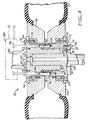
- Fig. 3 is a sectional view, taking along line 3-3, of the tyre holding fixture of Fig. 2; and
- Fig. 4 is an exploded view of the tyre holding fixture, showing the particular construction of the elements thereof.
- Referring generally to Fig. 1, a
tyre holding fixture 10, constructed according to the teachings of the present invention, is disclosed. Thetyre holding fixture 10 is just one element of a larger, more complextyre processing machine 12, partially shown in Fig. 1 and Fig. 2. Thetyre processing machine 12 can perform many, various processes upon aproduction tyre 13, such as balancing, grading, and grinding. The construction and function of thetyre processing machine 12 is well known in the art. - Upon careful consideration of Fig. 1, and Fig. 3, the particular construction of the
tyre holding fixture 10 becomes evident. Generally, thetyre holding fixture 10 comprises aspindle 14, aguide 16, a first, or lower,wheel half support 18, and a second, or upper,wheel half support 20. Thespindle 14 is connected to a drive means 22, located within the tyre processing.machine 12, by means of adrive shaft 24. In this manner, the drive means 22 is able to cause the entiretyre holding fixture 10 to rotate in order to process atyre 13. Thespindle 14 also has bores 25 therein. - The
guide 16 is mounted on thespindle 14 in coaxial fashion. Theguide 16 has amounting portion 26 and an extendingportion 28, and is substantially cylindrical in shape. Themounting portion 26 abuts thespindle 14. Themounting portion 26 hasapertures 30 of sufficient size to accept mountingbolts 32. Themounting bolts 32 communicate from theapertures 30 in themounting portion 26 to thebores 25 in thespindle 14, thereby attaching theguide 16 to thespindle 14, so that theguide 16 can rotate in unison with thespindle 14. The extendingportion 28 is substantially perpendicular to themounting portion 26, and extends along the axis of thespindle 14 and theguide 16. The extendingportion 28 protrudes beyond the upper edge of the lowerwheel half support 18, so that theguide 16 can center the lower and upper wheel half supports 18 and 20 about a common central axis. - The lower
wheel half support 18 has aninner diameter 34, anouter diameter 36, abase 38, and aleg 40. The lowerwheel half support 18 also hasapertures 42, and locking bores 44 therein. Theapertures 42 are of sufficient size to accept attachingbolts 44, and thelocking bores 44 are of sufficient size to acceptlocking pins 46, as will be discussed below. The attachingbolts 44 extend from some of theapertures 42 in the lower wheel half support 18 to thebores 25 in thespindle 14, thereby attaching the lowerwheel half support 18 to thespindle 14, so that the lowerwheel half support 18 can rotate in unison with thespindle 14, and theguide 16. Thebase 38 abuts thespindle 14, and theleg 40 is substantially perpendicular to thebase 38. The lowerwheel half support 18 is disposed upon thespindle 14, and about theguide 16 coaxially with thespindle 14, and theguide 16. Thus, theleg 40 is substantially cylindrical in shape. - Axially spaced, annular bands of no-lead thread segments, or radial projections, 48 are disposed upon the
inner diameter 34 of the lowerwheel half support 18, extending inwardly along theinner diameter 34 towards theguide 16. The no-lead thread segments 48 form part of a quick release locking means, or stepped bayonet retention system, the operation of which will be disclosed herein. - A toothed,
quick connect coupling 50, similar in construction to the curved tooth gear coupling disclosed in the patent of Belansky, U.S. Patent No. 4,307,797, assigned to the assignee of the present invention, is disposed about theouter diameter 36 of the lowerwheel half support 18. The disclosure of that patent is incorporated herein by this reference. Thetoothed coupling 50 is mounted on the lowerwheel half support 18 by means of mountingbolts 52, which communicate from thetoothed coupling 50 to theapertures 42 in the lowerwheel half support 18. Thetoothed coupling 50 supports a lowersimulated wheel half 54, which is constructed so as to accept and fix atyre 13. The structure and operation of the lowersimulated wheel half 14 will become more clear herein. - The upper
wheel half support 20 forms the remainder of thetyre holding fixture 10. The upperwheel half support 20 has abase 56, aleg 58, aninner diameter 60, and anouter diameter 62. The upperwheel half support 20 also hasapertures 64 and locking bores 66 therein. Thebase 56 is substantially perpendicular to theleg 58, and theleg 58 is substantially cylindrical in shape. - Both the
inner diameter 60 and theouter diameter 62 are smaller than theinner diameter 34 of the lowerwheel half support 18, and the distance between theguide 16 and theinner diameter 34 of the lowerwheel half support 18 is larger than the distance between theouter diameter 62 and theinner diameter 60 of the upperwheel half support 20. With this construction, theleg 58 of the upperwheel half support 20 is insertable within theleg 38 of the lowerwheel half support 18. - Axially spaced, annular band of no-lead thread segments, or radial projections, 68 are disposed on the
outer diameter 62 of the upperwheel half support 20, extending outwardly along theouter diameter 62. The nolead thread segments 68 are disposed in such a position so as to be insertable into the no-lead thread segments 48 disposed on theinner diameter 34 of the lowerwheel half support 18 when the upper wheel half support is inserted into the space between theguide 16 and theinner diameter 34 of the lowerwheel half support 18. - Both of the
thread segments inner diameter 34 or theouter diameter 62 of their respective wheel half supports 18 and 20. Instead, both of thethread segments inner diameter 34 and theouter diameter 62 of the lower and upper wheel half supports 18 and 20, respectively. This construction forms part of the quick release locking means, referred to as a multiple stepped bayonet retention system, including a plurality of interengaging segments spaced along the axis of thetyre holding fixture 10, capable of holding the lower and upper wheel half supports 18 and 20 during the processing of aproduction tyre 13, as shown in Fig. 2. - A toothed,
quick connect coupling 70, similar in construction to thetoothed coupling 50, is disposed about theouter diameter 62 of the upperwheel half support 20. Thetoothed coupling 70 is mounted to the upperwheel half support 20 by means of mountingbolts 72, which communicate from thetoothed coupling 70 to theapertures 64 in the upperwheel half support 20. Thetoothed coupling 70 supports an uppersimulated wheel half 74, which is of a construction similar to that of the lowersimulated wheel half 54, disposed about the lowersimulated wheel half 54. - The locking bores 66 in the upper
wheel half support 20 are of similar construction to the locking bores 44 in the lowerwheel half support 18, and are designed to accept locking pins 46. The locking bores 44 and 66 are disposed about their respective wheel half supports 18 and 20 in positions so that the locking pins 46 can be inserted in, and extend through both sets of locking bores 44 and 66, so that the lower and upper wheel half supports 18 and 20 can be joined, allowing for their co-rotation during the processing of atyre 13. In the preferred construction, the locking pins 46, and locking bores 44 and 66 form part of the quick release locking means. - Together, the lower
simulated wheel half 54 and the uppersimulated wheel half 74 form an apparatus which is able to hold aproduction tyre 13 for processing by thetyre processing machine 12. Specifically, the lowersimulated wheel half 54 has a bevelled surface 76, which is the mirror image of a bevelled surface 78 on the uppersimulated wheel half 74. Both of the bevelled surfaces 76 and 78 are constructed so as to imitate the mounting surface of an actual wheel. The bevelled surfaces 76 and 78, when in the proper relative positions dictated by the width of theproduction tyre 13, mimic the action of an actual wheel, and allow atyre 13 to be balanced, graded, ground, or otherwise processed as if thetyre 13 were actually mounted on a wheel. - As stated above, the
tyre holding fixture 10 is but part of a largertyre processing machine 12, well known in the art. The connections between thetyre holding fixture 10 and thetyre processing machine 12 are shown partially in Fig. 1, and Fig. 2. Thetyre processing machine 12, preferably, is hydraulic in nature, and is driven by hydraulic forces generated by a hydraulic power source 80. - The
spindle 14 is connected to the drive means 22, located within thetyre processing machine 12, by means of thedrive shaft 24. In this manner, the drive means 22 is able to cause the entiretyre holding fixture 10 to rotate when the locking pins 46 are disposed within both sets of locking bores 44 and 66, thereby locking the two wheel half supports 18 and 20 together. The upperwheel half support 20 is connected to drive means 82, such as a hydraulic piston, or the like, which is capable of translating the upperwheel half support 20 between an open position, as shown in Fig. 1, and a closed position, as shown in Fig. 2, so that thetyre holding fixture 10 can accept atyre 13. The drive means 82 also allows the upper wheel half support to rotate in unison with the lowerwheel half support 18. Another drive means 84, such as a piston, or the like, is connected to the locking pins 46. This drive means 84 is capable of translating the locking pins 46 into, and out of the locking bores 44 and 66, so that the two wheel half supports 18 and 20 are capable of co-rotation, and the two wheel half supports 18 and 20 are kept in a locked disposition. - The operation of the
tyre holding fixture 10 will become more clear from the following discussion. Referring initially to Fig. 1, thetyre holding fixture 10 is in the open position, ready to accept atyre 13 for processing. Atyre 13 is placed above the lowerwheel half support 18, and then is guided down into engagement with the bevelled surface 76 of the lowersimulated wheel half 54. - With the
tyre 13 engaging the bevelled surface 76, the drive means 82 forces the upperwheel half support 20 downward, inserting theleg 58 of the upperwheel half support 20 into the space between theguide 16 and theinner diameter 34 of the lowerwheel half support 18. Theguide 16 insures that the lower and upper wheel half supports 18 and 20 are centered about a common central axis, thereby insuring that thetyre 13 is centered about thetyre holding fixture 10. - At this time the no-
lead thread segments wheel half support 20 is forced downward a specific distance dictated by the width of thetyre 13, until thetyre 13 engages the bevelled surface 78 of the uppersimulated wheel half 74. When this occurs, the simulated wheel halves 54 and 74 act as an actual wheel, and thetyre 13 behaves as if it were mounted on an actual wheel. - When the upper
wheel half support 20 has been forced into the proper disposition by the drive means 82, the drive means 22 applies a rotational force to thedrive shaft 24, causing the lower wheel half support to rotate 30 degrees with respect to the upperwheel half support 20. This brings the no-lead thread segments lead thread segments tyre holding fixture 10 can accept and hold firmly tyres of varying widths for processing. - At this point, the drive means 84 forces the locking pins 46 through the locking bores 66 in the upper
wheel half support 20, and into the locking bores 44 in the lowerwheel half support 18. Thetyre holding fixture 10 is now in the closed position, shown in Fig. 2. In this manner, the lower and upper wheel half supports 18 and 20 are joined further, so that thetyre holding fixture 10 can rotate under the influence of rotational forces generated by the drive means 22, which are communicated to thetyre holding fixture 10 by means of thedrive shaft 24, which is connected to thespindle 14. - When the
tyre 13 has been processed properly, the drive means 22 ceases its rotation, bringing thetyre holding fixture 10 to rest. The drive means 84 now retracts the locking pins 46 out of the locking bores 44 in the lower wheel half support 18 a distance sufficient to allow the rotation of the lowerwheel half support 18 with respect to the upperwheel half support 20. The drive means 22 then rotates the lowerwheel half support 18 30 degrees, so as to disengage the no-lead thread segments wheel half support 20 to translate upwards, relieving the engagement between thetyre 13 and the bevelled surface 78 of the uppersimulated wheel half 74. The upperwheel half support 20 translates upward into the open position, shown in Fig. 1, and thetyre 13 is removed from thetyre holding fixture 10, which now is ready to process another tyre. - It must be emphasized that this entire process in automatic, requiring no human control, thereby increasing the speed of the process. The quick release locking means employed by the present invention allows a significant decrease in the amount of time needed to process each
production tyre 13. That means also allows a factory to have necessary versatility with respect to its machines. Specifically, because the quick release locking means is multi-stepped, thetyre holding fixture 10 can hold tyres of varying widths, thereby reducing the number of machines needed to service the production of different width tyres. Furthermore, thetyre holding fixture 10 can withstand separation forces, generated by tyre inflation and processing, on the order of 500,000 pounds (3.5GPa), thereby making the present invention a needed asset in the processing of tyres, especially tyres for trucks. These benefits of thetyre holding fixture 10 of the present invention can lead to increased production of tyres, and increased revenues from the sale of those tyres.
Claims (10)
- A tyre holding fixture capable of holding a tyre for use with a tyre processing machine (12) comprising: a first wheel half support (18), a second wheel half (20) support; one of the wheel half supports (74) being translatable between an open and a closed position so as to allow the tyre holding fixture to accept a tyre (B); and quick release locking means (44,46,48,68) for joining the wheel half supports (18,20) together.
- A tyre holding fixture according to claim 1, in which the wheel half supports (18,20) form a simulated wheel when the wheel half support (18) capable of translation is in the closed position; the first wheel half support (18) having an inner diameter; projections (48) being disposed about the inner diameter of the first wheel half support (74); the second wheel half support (20) having an outer diameter, with projections (88) disposed about the outer diameter; both projections (48,68) being capable of interengagement; the wheel half supports having bores (66) therein of sufficient size to accept locking pins (46); and the projections (48,68), bores (66), and locking pins (46) comprising the quick release locking means capable of joining and releasing the wheel half supports (18,20).
- A tyre holding fixture according to claim 1 or 2, wherein a cylindrical guide (34) is disposed coaxially with respect to one of the wheel half supports (18) so that the guide is capable of centering the wheel half supports (18,20) about a common axis.
- A tyre holding fixture according to any one of the preceding claims, wherein the projections (48,68) are multiple no-lead thread segments.
- A tyre holding fixture according to any one of the preceding claims, wherein the projections (48,68) are noncontinuous, and spaced along circumferences defined by their respective diameters.
- A tyre holding fixture as defined in claim 5, wherein the projections (48,68) are constructed in such a manner so that they can be brought into and out of interengagement by rotating one of the wheel half supports (18,20).
- A tyre holding fixture as defined in claim 5 or 6, wherein the projections (48,68) are spaced along circumferences defined by their respective diameters in alternating 30 degree segments.
- A tyre holding fixture according to any one of the preceding claims, wherein one of the wheel half supports (18) is connected to a spindle (24), the spindle (24) being capable of rotation, so that one or both wheel half supports (18,20) can be rotated, depending on the disposition of the quick release locking means.
- A tyre holding fixture as defined in any one of the preceding claims, wherein the locking pins (46) translate under the influence of a drive means (84).
- A tyre holding fixture according to any one of the preceding claims, wherein simulated wheel halves (54,74) are disposed about the wheel half supports (18,20), the simulated wheel halves (54,74) having bevelled surfaces constructed so as to mimic the construction of an actual wheel.
Applications Claiming Priority (2)
| Application Number | Priority Date | Filing Date | Title |
|---|---|---|---|
| US645743 | 1991-01-25 | ||
| US07/645,743 US5259242A (en) | 1991-01-25 | 1991-01-25 | Tire holding fixture for tire processing machine |
Publications (3)
| Publication Number | Publication Date |
|---|---|
| EP0496489A2 true EP0496489A2 (en) | 1992-07-29 |
| EP0496489A3 EP0496489A3 (en) | 1993-01-13 |
| EP0496489B1 EP0496489B1 (en) | 1995-12-13 |
Family
ID=24590298
Family Applications (1)
| Application Number | Title | Priority Date | Filing Date |
|---|---|---|---|
| EP92300067A Expired - Lifetime EP0496489B1 (en) | 1991-01-25 | 1992-01-06 | Tyre holding fixture for tyre processing machine |
Country Status (6)
| Country | Link |
|---|---|
| US (1) | US5259242A (en) |
| EP (1) | EP0496489B1 (en) |
| JP (1) | JPH04304940A (en) |
| CA (1) | CA2058639A1 (en) |
| DE (1) | DE69206635T2 (en) |
| ES (1) | ES2081560T3 (en) |
Cited By (3)
| Publication number | Priority date | Publication date | Assignee | Title |
|---|---|---|---|---|
| EP1612534A4 (en) * | 2003-04-09 | 2011-01-26 | Bridgestone Corp | Divided rim for tire, method of assembling rim/tire assembly, and method and device for installing rim/tire assembly |
| EP3633340A3 (en) * | 2018-09-14 | 2020-07-29 | Akron Special Machinery, Inc. | Dynamic balancer with a frameless motor drive |
| WO2020185170A1 (en) * | 2019-03-08 | 2020-09-17 | Me-Inspection Sk, S.R.O. | Clamping mechanism for a tyre testing device and method for clamping a tested tyre into the clamping mechanism |
Families Citing this family (11)
| Publication number | Priority date | Publication date | Assignee | Title |
|---|---|---|---|---|
| US5383361A (en) * | 1992-01-31 | 1995-01-24 | Kokusai Keisokuki Kabushiki Kaisha | Wheel balance measuring apparatus |
| JP3486307B2 (en) * | 1996-09-02 | 2004-01-13 | 三菱重工業株式会社 | Tire uniformity machine |
| JP3871580B2 (en) * | 2002-02-20 | 2007-01-24 | 株式会社ブリヂストン | Split rim for pneumatic tire |
| US7340947B2 (en) * | 2004-05-14 | 2008-03-11 | Kobe Steel, Ltd. | Tire testing machine and axis misalignment measuring method for tire testing machine |
| IT1392687B1 (en) * | 2009-01-27 | 2012-03-16 | Cappuccini | TIRE REGENERATION MACHINE |
| DE102009051823A1 (en) * | 2009-11-04 | 2011-05-05 | Fraunhofer-Gesellschaft zur Förderung der angewandten Forschung e.V. | Single-crystal welding of directionally solidified materials |
| JP5917041B2 (en) * | 2011-08-11 | 2016-05-11 | 大和製衡株式会社 | Rim changing device in tire balance measuring device |
| US10809157B2 (en) * | 2018-04-20 | 2020-10-20 | Akron Special Machinery, Inc. | Auto-adjust cylinder used with bead width adjusting apparatus |
| CN112677079B (en) * | 2020-12-18 | 2023-08-18 | 安徽东鸥机械科技有限公司 | Tire processing fixing device is used in truck production |
| JP7682532B2 (en) * | 2021-09-29 | 2025-05-26 | 株式会社長浜製作所 | Accuracy inspection method for tire testing machines |
| JP7721474B2 (en) * | 2022-03-25 | 2025-08-12 | 株式会社ブリヂストン | Tire mounting method, tire processing method, and tire holding device |
Family Cites Families (14)
| Publication number | Priority date | Publication date | Assignee | Title |
|---|---|---|---|---|
| US3331412A (en) * | 1966-04-25 | 1967-07-18 | Hawkinson Paul E Co | Tire holding apparatus |
| US3698233A (en) * | 1970-02-02 | 1972-10-17 | Goodyear Tire & Rubber | Apparatus for processing cured tires |
| US4185856A (en) * | 1973-04-13 | 1980-01-29 | Mcevoy Oilfield Equipment Company | Pipe joint with remotely operable latch |
| DE2616945C3 (en) * | 1976-04-17 | 1979-01-18 | Gebr. Hofmann Gmbh & Co Kg, Maschinenfabrik, 6100 Darmstadt | Device for clamping motor vehicle wheels |
| US4307797A (en) * | 1979-09-26 | 1981-12-29 | Illinois Tool Works Inc. | Curved tooth gear coupling |
| US4380927A (en) * | 1980-07-22 | 1983-04-26 | Sumitomo Rubber Industries, Ltd. | Rim mechanism for tire inspection arrangement |
| US4323414A (en) * | 1980-08-21 | 1982-04-06 | Branick Mfg., Inc. | Self-sealing curing rim for tubeless earthmover tire |
| US4414843A (en) * | 1980-09-19 | 1983-11-15 | The Goodyear Tire & Rubber Company | Tire dynamic imbalance screening system |
| KR870001804B1 (en) * | 1983-08-30 | 1987-10-13 | 가부시끼가이샤 고오베 세이꼬오쇼 | Automatic rim changer for tire uniformity checker |
| IT1176371B (en) * | 1984-06-29 | 1987-08-18 | Innocenti Santeustacchio Spa | JOINT FOR HEAD-TO-HEAD CONNECTION OF METAL TUBES, IN PARTICULAR FOR MARINE PALLING |
| US4677848A (en) * | 1985-12-02 | 1987-07-07 | Monsanto Company | Multi-size tire chuck |
| US4787150A (en) * | 1987-10-05 | 1988-11-29 | The Firestone Tire & Rubber Company | Fixture for checking the alignment of a loadwheel with the spindle of a tire uniformity machine |
| US4852398A (en) * | 1988-03-09 | 1989-08-01 | Eagle-Picher Industries, Inc. | Tire testing machine having adjustable bead width |
| JPH03188348A (en) * | 1989-12-18 | 1991-08-16 | Kobe Steel Ltd | Adjusting apparatus for automatic rim-width of tire uniformity machine |
-
1991
- 1991-01-25 US US07/645,743 patent/US5259242A/en not_active Expired - Lifetime
- 1991-12-31 CA CA002058639A patent/CA2058639A1/en not_active Abandoned
-
1992
- 1992-01-06 DE DE69206635T patent/DE69206635T2/en not_active Expired - Lifetime
- 1992-01-06 ES ES92300067T patent/ES2081560T3/en not_active Expired - Lifetime
- 1992-01-06 EP EP92300067A patent/EP0496489B1/en not_active Expired - Lifetime
- 1992-01-22 JP JP4029954A patent/JPH04304940A/en active Pending
Cited By (7)
| Publication number | Priority date | Publication date | Assignee | Title |
|---|---|---|---|---|
| EP1612534A4 (en) * | 2003-04-09 | 2011-01-26 | Bridgestone Corp | Divided rim for tire, method of assembling rim/tire assembly, and method and device for installing rim/tire assembly |
| EP3633340A3 (en) * | 2018-09-14 | 2020-07-29 | Akron Special Machinery, Inc. | Dynamic balancer with a frameless motor drive |
| EP3848686A1 (en) * | 2018-09-14 | 2021-07-14 | Akron Special Machinery, Inc. | Dynamic balancer with a frameless motor drive |
| US11333569B2 (en) | 2018-09-14 | 2022-05-17 | Akron Special Machinery, Inc. | Dynamic balancer with a frameless motor drive |
| CN117433699A (en) * | 2018-09-14 | 2024-01-23 | 阿克隆特种机械公司 | Dry brake air mechanism, clamping assembly, return cylinder and encoder assembly |
| WO2020185170A1 (en) * | 2019-03-08 | 2020-09-17 | Me-Inspection Sk, S.R.O. | Clamping mechanism for a tyre testing device and method for clamping a tested tyre into the clamping mechanism |
| US11397137B2 (en) | 2019-03-08 | 2022-07-26 | Me-Inspection Sk, S.R.O. | Clamping mechanism for a tyre testing device and method for clamping a tested tyre into the clamping mechanism |
Also Published As
| Publication number | Publication date |
|---|---|
| DE69206635D1 (en) | 1996-01-25 |
| DE69206635T2 (en) | 1996-05-02 |
| ES2081560T3 (en) | 1996-03-16 |
| CA2058639A1 (en) | 1992-07-26 |
| EP0496489A3 (en) | 1993-01-13 |
| EP0496489B1 (en) | 1995-12-13 |
| US5259242A (en) | 1993-11-09 |
| JPH04304940A (en) | 1992-10-28 |
Similar Documents
| Publication | Publication Date | Title |
|---|---|---|
| EP0496489B1 (en) | Tyre holding fixture for tyre processing machine | |
| EP0574132A1 (en) | Tyre holding fixture | |
| EP1464942B1 (en) | Apparatus and method for measuring tire balance on a force variation machine | |
| US3698233A (en) | Apparatus for processing cured tires | |
| AU766962B2 (en) | Snug fitting apparatus for tire assembly | |
| US5503508A (en) | Apparatus for, and method of, drilling lug holes and valve stem holes in motor vehicle wheels | |
| US6516855B2 (en) | Wheel rim locking device for tire removal machines | |
| US5033003A (en) | Wheel measuring machine | |
| US3977131A (en) | Tire grinding machines | |
| EP3924707B1 (en) | Clamping mechanism for a tyre testing device and method for clamping a tested tyre into the clamping mechanism | |
| US4610288A (en) | Apparatus for mounting pneumatic vehicle tires | |
| US4886101A (en) | Wheel/tire load simulating apparatus | |
| US4034786A (en) | Wheel chuck | |
| US3656343A (en) | Apparatus for processing cured tires | |
| EP0000423B1 (en) | Tire building machine | |
| US4763710A (en) | Rim and spindle for tire uniformity machines | |
| EP0275088B1 (en) | Tire uniformity machine and method | |
| JP2003004597A (en) | Uniformity and / or dynamic balance testing equipment for tires with wheels | |
| US1445784A (en) | J sheets-sheet | |
| EP0379009A2 (en) | Quick-coupling device particularly for coupling rotating tools to a driving unit | |
| US7703206B1 (en) | Universal wheel pylon | |
| EP0518886A1 (en) | Stepped rim for tire testing machine | |
| CA1264435A (en) | Apparatus for building tires | |
| US3049159A (en) | Wheel support and lock for tire demounting apparatus | |
| US3589705A (en) | Apparatus supporting rim mounted tire rotation in predetermined plane |
Legal Events
| Date | Code | Title | Description |
|---|---|---|---|
| PUAI | Public reference made under article 153(3) epc to a published international application that has entered the european phase |
Free format text: ORIGINAL CODE: 0009012 |
|
| AK | Designated contracting states |
Kind code of ref document: A2 Designated state(s): DE ES FR GB IT |
|
| PUAL | Search report despatched |
Free format text: ORIGINAL CODE: 0009013 |
|
| AK | Designated contracting states |
Kind code of ref document: A3 Designated state(s): DE ES FR GB IT |
|
| 17P | Request for examination filed |
Effective date: 19930702 |
|
| 17Q | First examination report despatched |
Effective date: 19941028 |
|
| GRAA | (expected) grant |
Free format text: ORIGINAL CODE: 0009210 |
|
| AK | Designated contracting states |
Kind code of ref document: B1 Designated state(s): DE ES FR GB IT |
|
| REF | Corresponds to: |
Ref document number: 69206635 Country of ref document: DE Date of ref document: 19960125 |
|
| ITF | It: translation for a ep patent filed | ||
| ET | Fr: translation filed | ||
| REG | Reference to a national code |
Ref country code: ES Ref legal event code: FG2A Ref document number: 2081560 Country of ref document: ES Kind code of ref document: T3 |
|
| PLBE | No opposition filed within time limit |
Free format text: ORIGINAL CODE: 0009261 |
|
| 26N | No opposition filed | ||
| PGFP | Annual fee paid to national office [announced via postgrant information from national office to epo] |
Ref country code: FR Payment date: 19971218 Year of fee payment: 7 |
|
| PGFP | Annual fee paid to national office [announced via postgrant information from national office to epo] |
Ref country code: DE Payment date: 19971222 Year of fee payment: 7 |
|
| PGFP | Annual fee paid to national office [announced via postgrant information from national office to epo] |
Ref country code: GB Payment date: 19971223 Year of fee payment: 7 |
|
| PGFP | Annual fee paid to national office [announced via postgrant information from national office to epo] |
Ref country code: ES Payment date: 19980121 Year of fee payment: 7 |
|
| PG25 | Lapsed in a contracting state [announced via postgrant information from national office to epo] |
Ref country code: DE Free format text: LAPSE BECAUSE OF THE APPLICANT RENOUNCES Effective date: 19981118 |
|
| PG25 | Lapsed in a contracting state [announced via postgrant information from national office to epo] |
Ref country code: GB Free format text: LAPSE BECAUSE OF NON-PAYMENT OF DUE FEES Effective date: 19990106 |
|
| PG25 | Lapsed in a contracting state [announced via postgrant information from national office to epo] |
Ref country code: ES Free format text: LAPSE BECAUSE OF NON-PAYMENT OF DUE FEES Effective date: 19990107 |
|
| GBPC | Gb: european patent ceased through non-payment of renewal fee |
Effective date: 19990106 |
|
| PG25 | Lapsed in a contracting state [announced via postgrant information from national office to epo] |
Ref country code: FR Free format text: LAPSE BECAUSE OF NON-PAYMENT OF DUE FEES Effective date: 19990930 |
|
| REG | Reference to a national code |
Ref country code: FR Ref legal event code: ST |
|
| REG | Reference to a national code |
Ref country code: ES Ref legal event code: FD2A Effective date: 20011010 |
|
| PG25 | Lapsed in a contracting state [announced via postgrant information from national office to epo] |
Ref country code: IT Free format text: LAPSE BECAUSE OF NON-PAYMENT OF DUE FEES Effective date: 20050106 |