EP0495614A2 - Method of injection molding a thermoplastic resin and a mold for injection molding - Google Patents
Method of injection molding a thermoplastic resin and a mold for injection molding Download PDFInfo
- Publication number
- EP0495614A2 EP0495614A2 EP92300288A EP92300288A EP0495614A2 EP 0495614 A2 EP0495614 A2 EP 0495614A2 EP 92300288 A EP92300288 A EP 92300288A EP 92300288 A EP92300288 A EP 92300288A EP 0495614 A2 EP0495614 A2 EP 0495614A2
- Authority
- EP
- European Patent Office
- Prior art keywords
- void
- resin
- molding
- mold
- inducing member
- Prior art date
- Legal status (The legal status is an assumption and is not a legal conclusion. Google has not performed a legal analysis and makes no representation as to the accuracy of the status listed.)
- Granted
Links
Images


Classifications
-
- B—PERFORMING OPERATIONS; TRANSPORTING
- B29—WORKING OF PLASTICS; WORKING OF SUBSTANCES IN A PLASTIC STATE IN GENERAL
- B29C—SHAPING OR JOINING OF PLASTICS; SHAPING OF MATERIAL IN A PLASTIC STATE, NOT OTHERWISE PROVIDED FOR; AFTER-TREATMENT OF THE SHAPED PRODUCTS, e.g. REPAIRING
- B29C45/00—Injection moulding, i.e. forcing the required volume of moulding material through a nozzle into a closed mould; Apparatus therefor
- B29C45/17—Component parts, details or accessories; Auxiliary operations
- B29C45/76—Measuring, controlling or regulating
-
- B—PERFORMING OPERATIONS; TRANSPORTING
- B29—WORKING OF PLASTICS; WORKING OF SUBSTANCES IN A PLASTIC STATE IN GENERAL
- B29C—SHAPING OR JOINING OF PLASTICS; SHAPING OF MATERIAL IN A PLASTIC STATE, NOT OTHERWISE PROVIDED FOR; AFTER-TREATMENT OF THE SHAPED PRODUCTS, e.g. REPAIRING
- B29C45/00—Injection moulding, i.e. forcing the required volume of moulding material through a nozzle into a closed mould; Apparatus therefor
- B29C45/17—Component parts, details or accessories; Auxiliary operations
- B29C45/1703—Introducing an auxiliary fluid into the mould
- B29C45/1704—Introducing an auxiliary fluid into the mould the fluid being introduced into the interior of the injected material which is still in a molten state, e.g. for producing hollow articles
-
- B—PERFORMING OPERATIONS; TRANSPORTING
- B29—WORKING OF PLASTICS; WORKING OF SUBSTANCES IN A PLASTIC STATE IN GENERAL
- B29C—SHAPING OR JOINING OF PLASTICS; SHAPING OF MATERIAL IN A PLASTIC STATE, NOT OTHERWISE PROVIDED FOR; AFTER-TREATMENT OF THE SHAPED PRODUCTS, e.g. REPAIRING
- B29C45/00—Injection moulding, i.e. forcing the required volume of moulding material through a nozzle into a closed mould; Apparatus therefor
- B29C45/17—Component parts, details or accessories; Auxiliary operations
- B29C45/26—Moulds
Definitions
- the present invention relates to a method of injection-molding a thermoplastic resin into a molding and a mold for the injection molding, and more particularly to a method of molding the resin into a mold having sections which are different in thickness, without generating defects such as sink marks which are caused by shrinkage of resin.
- thermoplastic resin When thermoplastic resin is injection-molded into an article having heavy sections and thinner sections, the heavy section's resin solidifies later than the thinner section's resin so that the filled resin into the mold is faster cooled and solidified, in the cooling process.
- shrinkage of the resin occurs mainly in the heavy section's resin, which often causes defects such as sink marks, deformations and other defects on the surfaces of the heavy sections.
- the sink marks, deformations, and other defects cause the value of the article to be considerably reduced.
- a "dwell-time" is allowed immediately after the completion of the filling of resin. Accordingly the pressure is maintained for a short time after the filling of the resin, so as to prevent sink marks from being generated.
- the gates are likely to solidify before the dwell-time has elapsed. Therefore, an article having a satisfactory appearance cannot be obtained.
- Japanese Patent Application Publication 61-53208, Japanese Patent Application Laid Open 63-268611 and 64-63122 disclose methods for suppressing a generation of surface defects by supplying gas through the resin passageway at a high pressure to make a hollow in the heavy sections and holding the resin under the pressure.
- a sufficient hollow is not formed in the article, causing surface defects such as sink marks.
- the gas passages serve as flow leaders for the molten resin, so defects such as air traps and flow marks may be easily generated on the surface of the article.
- high pressure gas blows out from the article. Therefore, the range of articles which can be produced is limited in shape. Furthermore, it is not easy to handle the high pressure gas.
- the mold has some portions which are difficult to be cooled.
- the void control members must have a large heat capacity and a high temperature. Accordingly, it is difficult to make the void control members smaller in size. As a result, it is restricted to locate the void inducing members at the desirable positions in the mold, and hence it is difficult to form the void in all of the necessary portions in the molding.
- positions generating sink marks change irregularly affected by the molding conditions. Furthermore, in some resins such as polyacetal, voids to compensate the shrinkage can not be generated sufficiently. Therefore, generation of sink marks can not be prevented sufficiently.
- Japanese Patent Application Publication 48-41264 discloses a method of injection-molding where a nozzle is projected into a cavity of a mold and gas is supplied into a resin in the cavity from a tip end of the nozzle at a high pressure before solidification of the resin, passing through a passage formed in the axis of the nozzle.
- the method also uses a high pressure gas, it is difficult to control the pressure to form a preferable void.
- the nozzle can be trapped by the shrinkage force of the solidified resin. Therefore, the nozzle cannot be smoothly removed from the resin.
- the present invention therefore seeks to provide a method for making a molding having heavy section in which sink marks, deformations and other defects are prevented from occurring by applying gas pressure by means of void inducing members incorporated in an appropriate position of the mold to cause a void in the resin near ends of void inducing members.
- an injection-molding method for a thermoplastic resin molding having portions of different thicknesses to prevent formation of sink marks on the surface of the molding which is characterized by; 1) providing at least one void inducing member positioned in a mold cavity corresponding to the or each heavy section where sink marks may be generated on its surfaces, 2) filling the said cavity with molten resin by injection, 3) forming a void-nucleus in the molten resin at the end of said void inducing members by applying gas pressure to break through the skin of the solidified resin adjacent to the pin end of the said void inducing members along with the said void inducing members, and 4) developing the aid voids to such a size equivalent to the volume shrinkage made by the shrinkage force followed from cooling and solidifying setting of the said molten resin.
- the application of gas pressure may be performed either immediately after the filling of the entire cavity with resin or may be performed with the above described dwell-time. By this dwell process, the decrease in the charge pressure caused by the counter flow of the injected resin from a cavity can be also prevented.
- This method is also effective for promoting the said void to develop to the size corresponding to the volume shrinkage made by its force followed from cooling and solidifying of the said void by the following procedures.
- the gas pressure is applied to the injected resin from the pin end along the periphery or passing an axis hole of the void inducing members to induce voids, which should be continued until the end of the cooling of the resin.
- the gas pressure applied in accordance with the shrinkage of the resin brought with the cooling and solidification the development of the voids can be accelerated.
- a mold used for performing this injection molding is characterized by having a cavity which is composed of both heavy thick and thinner sections depending on the shape of articles to be manufactured, having void inducing members of which end is projected in the heavy sections of the said cavity and passageway provided vertically around the said void inducing members for supplying a gas pressure and having void inducing members with an projected tip end.
- the void inducing member may also act as an ejector for ejecting the product from the mold.
- the cavity of the mold is charged fully with the injected resin, and gas pressure is applied to the resin through the void inducing member immediately or after dwelling.
- gas pressure is applied to the resin through the void inducing members, the gas breaks through the skin layer being formed around the tip end of the void inducing members to form microscopic foam in the molten resin as a nucleus for the void.
- the void nucleus progressively develops to voids by the shrinkage force along with the cooling and solidification of the surrounding molten resin.
- the voids generated as a nucleus continues to develop until they becomes large enough to prevent sink marks from generating.
- sink marks do not generate not only around the void inducing members, but also all over the heavy sections. If the gas application is continued, the gas pressure is added to the shrinkage force, thereby enhancing the development of the void. As a result, sink marks are not formed on the heavy sections, but also around the thinner sections or on the adjacent thinner sections.
- the diameter of the hole formed in the skin layer which is being formed at the tip end of void inducing member(s) is approximately 0.5 mm which is hardly distinguishable, so that the appearance of the product is not injured.
- the diameter of the void inducing member though not limited particularly, is required to be 1 mm or over preferably 1 to 10 mm, more preferably 1 to 5 mm taking the strength into account.
- the position of the end of the void inducing member(s) is in the heavy sections of the cavity, and not necessarily in its center.
- the location for mounting the void inducing members is not limited in particular, which can be built at any convenient place in respect of designing the product. Sufficient effect, will be obtained even if it is set at the end of heavy sections. Since it is not necessary to increase heat capacity of the void inducing member(s), and not to locate the void inducing member(s) at limited positions where sink marks are easily formed, as is desclosed in Japanese Patent Publication 2-13886, the freedom in designing a product becomes uncomparatively high. If the void inducing member is so designed that gas pressure concentrates effectively at an end thereof, it is not necessary to have the shape of cylindrical rod.
- the gas pressure to be used can be approximately 5 to 15 kg/cm2, which is much lower than the pressure used in the hollow in the heavy sections disclosed in Japanese Patent Publication 61-53208. In most cases, the air pressure of 10 kg/cm2 or less will be sufficient and its supply source can be easily obtained. Such a low pressure gas can be easily obtained by an ordinary operating system.
- the gas pressure necessary for forming a hollow in heavy sections by the methods disclosed in Japanese Patent Publications 57-14968 and 61-53208 is 150 kg/cm2.
- the gas is fed into the resin along the periphery of the void inducing member. Consequently, the gas forms a slight gap between the void inducing member and the resin. Accordingly, the void inducing member can be easily removed from the resin, unlike the method disclosed in Japanese Patent Application Publication 48-41264.
- the complete molding 10 has a rib 12 as heavy sections and a flange 11 as thinner sections.
- a gate 13 remains, which has been formed in a sprue of a mold, and is to be cut off to obtain an article.
- the rib has a thickness of 10 mm while the flange 11 has a thickness of 3 mm. Because of this large thickness, sink marks are liable to be formed at surface portions 14, 15 and 16 of rib 12 when molded by a conventional injection molding.
- Fig. 2 shows a mold 20 for the molding 10 which comprises a fixed mold 22 and a movable mold 23 attached to the fixed mold 22 to form a cavity 21.
- a sprue gas 13a is formed in the mold.
- void inducing members 30 are mounted in the movable mold 23.
- the void inducing member 30 is in the form of a rod and has an acute tip 31 and screw thread 38.
- the member 30 is inserted into a hole 24 formed in the movable mold 23, and the thread 38 is screwed in the movable mold 23.
- a flange 32 of the void inducing member 30 is abutted on the outside wall of the mold 23.
- the tip 31 is located at a central portion of the cavity 21.
- the hole 24 comprises a large diameter portion 25 around a base portion of the void inducing member 30 and a small diameter portion 26 having a diameter slightly larger than the void inducing member 30.
- the large diameter portion 25 is communicated with a pressurized gas source 27 through a passage 28 and a valve 29.
- the cavity 21 is charged with resin 40 (Fig. 3), such as polystyrene, polypropylene, ABS or polycarbonate, injected by an injection molding machine.
- resin 40 such as polystyrene, polypropylene, ABS or polycarbonate
- the present invention is effective to mold polypropylene or ABS having a large mold shrinkage.
- the void nucleuses 43 are expanded by the shrinkage force of the resin 40 to voids 44 as shown in Fig. 4.
- the void 44 develops as shown by reference I and II to a molten resin 40a which remains molten because of delay of cooling and solidifying.
- the mold 20 is opened to take out the molding. No sink marks are formed on the surface of the molding owing to the voids in the molding. If the application of the gas pressure is continued to the end of the solidification without releasing, the development of the void is enhanced, since the gas pressure is added to the shrinkage force of the resin. Thus, the developed voids prevent sink marks from generating at a peripheral portion of the heavy sections.
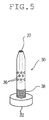
- Fig. 5 shows another example of the void inducing member 30.
- the void inducing member 30 has an axial hole 37 and a plurality of lateral holes 36 communicated with the axial hole 37 and with the large diameter portion 25 of the hole 24. Consequently, gas supplied from the source 27 enters the axial holes 37 passing through the lateral holes 36 and spouts from the opening of the tip of the member 30, thereby forming a void nucleus in the resin.
- Fig. 6 shows further another example of the void inducing member.
- Each void inducing member 30a is secured to a holding plate 23a fixed to the movable mold 23.
- the passage 28 for supplying a gas pressure is formed between the mold 23 and the holding plate 23a and communicated with the hold 24 at the bottom thereof.
- Function of the void generating member 30a is the same as the member 30 of Fig. 2.
- the molding had a shape shown in Fig. 1, where the rib 12 had a length of 230mm and a thickness of 10mm, and the flange 11 had a thickness of 3mm.
- the mold 20 of Fig. 2 was used, where three void inducing members 30 were disposed at an interval of 100mm. Each member had a diameter of 2mm. Molten polystyrene was injected in the cavity 21 of the mold. Immediately after dwelling for three seconds, compressed air of 9.5 kg/cm2 at a room temperature was applied to the tip of each void inducing member 30 for eight seconds. Then, the air was discharged to the atmosphere by opening the valve 29. The resin was cooled and solidified under the open condition of the passage 28.
- Fig. 7 shows the relationship. From the graph, it is found that the void nucleus is formed within five seconds after the start of the gas pressure application. The size of the void increases with the gas pressure application time. When the surface state of the resin molding was observed in detail, it is improved as the size of the void increases.
- the weight of the injected product with the dwelling was 133.9g and was 131.2g without dwelling.
- the gas pressure was applied to the tip end of the void inducing member immediately after the start of the cooling period.
- the relationship between the delay time starting the gas pressure application at different times and the size of voids formed and surface quality was compared in the same conditions as the Example II.
- Fig. 8 shows the relationship between the gas pressure application start time and size of the void. From the graph, it is found that the development of resin solidifying layer is performed before the development of the void, the shrinkage of resin, causing sink marks, cannot be compensated by the void, resulting in insufficient improvement of the surface state.
- Fig. 9 shows results of the Examples I through IV and the Comparative Example.
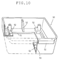
- Fig. 10 shows a molding 50 having a complicated shape.
- the molding comprises thinner sections 51 and heavy sections 52.
- void inducing members were provided in the cavity of a mold corresponding to the positions indicated by marks x and +.
- the gas pressure was applied immediately after injecting the molten resin into a mold cavity, a product could be obtained after the completion of cooling, which was excellent in appearance without having any defect such as sink mark on the surface despite of the complicate form of the product.
- the void inducing member 30a of Fig. 11 was set.
- the void inducing member 30a was attached by an attaching device shown in Fig. 11.
- the void inducing member 30a is mounted to a bottom plate 53 which is secured to a core plate 23a through a spacer block 54.
- the member 30a is mounted in a sleeve 55 which is supported by an ejector plate 56. Between the member 30a and the sleeve 55, a gas passage 57 is formed to be communicated with the tip end of void inducing member in the mold 23a.
- the passage 57 is sealed by an O-ring 58.
- the pressurized gas is applied to the cavity 21a through the pipe 60, a connector 61 and passage 57.
- the attaching device of Fig. 11 enables the void generating member to be easily attached to a mold having a complicated shape.
- the void inducing member may also act as an ejector for ejecting the product from the mold.
- foams as a void nucleus are formed on the tip of a void inducing member in the injected resin.
- This void nucleus develops to voids as the resin shrinks when solidified at cooling.
- gas pressure having a low pressure is applied to the void inducing member, the injection molding can be easily performed with an injector having a simple construction.
Landscapes
- Engineering & Computer Science (AREA)
- Manufacturing & Machinery (AREA)
- Mechanical Engineering (AREA)
- Injection Moulding Of Plastics Or The Like (AREA)
- Moulds For Moulding Plastics Or The Like (AREA)
- Diaphragms For Electromechanical Transducers (AREA)
Abstract
Description
- The present invention relates to a method of injection-molding a thermoplastic resin into a molding and a mold for the injection molding, and more particularly to a method of molding the resin into a mold having sections which are different in thickness, without generating defects such as sink marks which are caused by shrinkage of resin.
- When thermoplastic resin is injection-molded into an article having heavy sections and thinner sections, the heavy section's resin solidifies later than the thinner section's resin so that the filled resin into the mold is faster cooled and solidified, in the cooling process.
- Consequently, shrinkage of the resin occurs mainly in the heavy section's resin, which often causes defects such as sink marks, deformations and other defects on the surfaces of the heavy sections. The sink marks, deformations, and other defects (which are referred to as sink marks hereinafter) cause the value of the article to be considerably reduced. By the conventional injection-molding method, in order to compensate the shrinkage, a "dwell-time" is allowed immediately after the completion of the filling of resin. Accordingly the pressure is maintained for a short time after the filling of the resin, so as to prevent sink marks from being generated. However, when an article having a complicated shape is molded, the gates are likely to solidify before the dwell-time has elapsed. Therefore, an article having a satisfactory appearance cannot be obtained.
- Japanese Patent Application Publication 61-53208, Japanese Patent Application Laid Open 63-268611 and 64-63122 disclose methods for suppressing a generation of surface defects by supplying gas through the resin passageway at a high pressure to make a hollow in the heavy sections and holding the resin under the pressure. However, when an article having a complicated shape is molded, a sufficient hollow is not formed in the article, causing surface defects such as sink marks. In addition, the gas passages serve as flow leaders for the molten resin, so defects such as air traps and flow marks may be easily generated on the surface of the article. In an extreme case, high pressure gas blows out from the article. Therefore, the range of articles which can be produced is limited in shape. Furthermore, it is not easy to handle the high pressure gas.
- As another method, it is know to apply a pressure to the heavy sections from the back side of the article after the filling of resin. There are two pressures applying modes. In one mode, a part of the mold is arranged to be movable and pressed against the article by the hydraulic ram. The other mode is characterized by directly pressuring the article with gas from the rear surface of the heavy sections (Japanese Patent Application Publication 61-9126). However, the former method requires a mold with a complicated structure or special type of molding machine. The latter method also causes irregular sink marks on the back side of the product, resulting in considerable reduction in the value of the article.
- Meanwhile, when the resin such as polycarbonate and polymethyl-methacrylate having a high setting speed are injection-molded, the surface layers are cooled and solidified quickly, and they will be strong enough to hold the internal stress of shrinkage. Consequently, voids will form inside of the molding. Accordingly sink marks are not formed on the surface of the heavy sections.
- This generation of the void has been regarded as a defect causing the strength of the article to decrease. However positive use of the void to prevent the sink marks is disclosed in Japanese Patent Application Publication 2-13886. In this method, a void control member is projected into the cavity where sink marks are apt to generate. The void control member acts to induce a void in the resin at the portion near the end of the member, thereby preventing sink marks. This method is effective since sink marks can be prevented by simple means.
- However, to the form the voids in the molding, the mold has some portions which are difficult to be cooled. Namely, the void control members must have a large heat capacity and a high temperature. Accordingly, it is difficult to make the void control members smaller in size. As a result, it is restricted to locate the void inducing members at the desirable positions in the mold, and hence it is difficult to form the void in all of the necessary portions in the molding. In addition, positions generating sink marks change irregularly affected by the molding conditions. Furthermore, in some resins such as polyacetal, voids to compensate the shrinkage can not be generated sufficiently. Therefore, generation of sink marks can not be prevented sufficiently.
- Japanese Patent Application Publication 48-41264 discloses a method of injection-molding where a nozzle is projected into a cavity of a mold and gas is supplied into a resin in the cavity from a tip end of the nozzle at a high pressure before solidification of the resin, passing through a passage formed in the axis of the nozzle. However, since the method also uses a high pressure gas, it is difficult to control the pressure to form a preferable void. In addition, the nozzle can be trapped by the shrinkage force of the solidified resin. Therefore, the nozzle cannot be smoothly removed from the resin.
- The present invention therefore seeks to provide a method for making a molding having heavy section in which sink marks, deformations and other defects are prevented from occurring by applying gas pressure by means of void inducing members incorporated in an appropriate position of the mold to cause a void in the resin near ends of void inducing members.
- According to the present invention, there is provided an injection-molding method for a thermoplastic resin molding having portions of different thicknesses to prevent formation of sink marks on the surface of the molding, which is characterized by; 1) providing at least one void inducing member positioned in a mold cavity corresponding to the or each heavy section where sink marks may be generated on its surfaces, 2) filling the said cavity with molten resin by injection, 3) forming a void-nucleus in the molten resin at the end of said void inducing members by applying gas pressure to break through the skin of the solidified resin adjacent to the pin end of the said void inducing members along with the said void inducing members, and 4) developing the aid voids to such a size equivalent to the volume shrinkage made by the shrinkage force followed from cooling and solidifying setting of the said molten resin.
- The application of gas pressure may be performed either immediately after the filling of the entire cavity with resin or may be performed with the above described dwell-time. By this dwell process, the decrease in the charge pressure caused by the counter flow of the injected resin from a cavity can be also prevented.
- This method is also effective for promoting the said void to develop to the size corresponding to the volume shrinkage made by its force followed from cooling and solidifying of the said void by the following procedures.
- The gas pressure is applied to the injected resin from the pin end along the periphery or passing an axis hole of the void inducing members to induce voids, which should be continued until the end of the cooling of the resin. In this case, when changing the gas pressure applied in accordance with the shrinkage of the resin brought with the cooling and solidification, the development of the voids can be accelerated.
- A mold used for performing this injection molding is characterized by having a cavity which is composed of both heavy thick and thinner sections depending on the shape of articles to be manufactured, having void inducing members of which end is projected in the heavy sections of the said cavity and passageway provided vertically around the said void inducing members for supplying a gas pressure and having void inducing members with an projected tip end. The void inducing member may also act as an ejector for ejecting the product from the mold.
- The cavity of the mold is charged fully with the injected resin, and gas pressure is applied to the resin through the void inducing member immediately or after dwelling. As the molding starts to cool the residual filling pressure within the molding falls to zero and quickly becomes negative. At that time, the gas pressure is applied to the resin through the void inducing members, the gas breaks through the skin layer being formed around the tip end of the void inducing members to form microscopic foam in the molten resin as a nucleus for the void. Even if the application of the gas pressure is stopped after the void nucleus has been once formed, the void nucleus progressively develops to voids by the shrinkage force along with the cooling and solidification of the surrounding molten resin. Thus, by compensating the shrinkage forces one after another, the voids generated as a nucleus continues to develop until they becomes large enough to prevent sink marks from generating. In this way, sink marks do not generate not only around the void inducing members, but also all over the heavy sections. If the gas application is continued, the gas pressure is added to the shrinkage force, thereby enhancing the development of the void. As a result, sink marks are not formed on the heavy sections, but also around the thinner sections or on the adjacent thinner sections.
- When a void inducing member having a projected tip end is used, gas pressure application is concentrated in the tip end, thereby easily forming a void nucleus as well as enhancing the repeatability of generating a void at optional positions. The diameter of the hole formed in the skin layer which is being formed at the tip end of void inducing member(s) is approximately 0.5 mm which is hardly distinguishable, so that the appearance of the product is not injured. The diameter of the void inducing member, though not limited particularly, is required to be 1 mm or over preferably 1 to 10 mm, more preferably 1 to 5 mm taking the strength into account. It is sufficient that the position of the end of the void inducing member(s) is in the heavy sections of the cavity, and not necessarily in its center. Furthermore, the location for mounting the void inducing members is not limited in particular, which can be built at any convenient place in respect of designing the product. Sufficient effect, will be obtained even if it is set at the end of heavy sections. Since it is not necessary to increase heat capacity of the void inducing member(s), and not to locate the void inducing member(s) at limited positions where sink marks are easily formed, as is desclosed in Japanese Patent Publication 2-13886, the freedom in designing a product becomes uncomparatively high. If the void inducing member is so designed that gas pressure concentrates effectively at an end thereof, it is not necessary to have the shape of cylindrical rod.
- The gas pressure to be used can be approximately 5 to 15 kg/cm², which is much lower than the pressure used in the hollow in the heavy sections disclosed in Japanese Patent Publication 61-53208. In most cases, the air pressure of 10 kg/cm² or less will be sufficient and its supply source can be easily obtained. Such a low pressure gas can be easily obtained by an ordinary operating system. The gas pressure necessary for forming a hollow in heavy sections by the methods disclosed in Japanese Patent Publications 57-14968 and 61-53208 is 150 kg/cm². In the method of the present invention, as it is not necessary to use such a high-pressurized nitrogen gas as 150 kg/cm² required for forming a hollow in heavy sections by the methods disclosed in Japanese Patent Publications 57-14968 and 61-53208, no special structure in equipment nor operation conditions are needed. Therefore, sink marks do not generate even under ordinary operating conditions, enabling to obtain easily a molded article with excellent surface properties, and thus attaining inestimable superiority over the others. In the method of the present invention, even if the gas has a low pressure, the development of a void is accelerated and sink marks can be effectively prevented, in particular in the resin having a strong shrinkage force. If the gas pressure application is continued during the cooling step of the resin to promote the development of the void to compensate the shrinkage of the resin, sink marks are more perfectly prevented from generating.
- The gas is fed into the resin along the periphery of the void inducing member. Consequently, the gas forms a slight gap between the void inducing member and the resin. Accordingly, the void inducing member can be easily removed from the resin, unlike the method disclosed in Japanese Patent Application Publication 48-41264.
- The other objects and features of this invention will become understood from the following description with reference to the accompanying drawings.
-
- Fig. 1 is a perspective view showing an example of a complete molding;
- Fig. 2 is a sectional side view of a mold using a method of the present invention;
- Fig. 3 is a sectional view for explaining formation of a void nucleus;
- Fig. 4 is a sectional view for explaining development of a void;
- Fig. 5 is a perspective view showing another example of a void inducing member;
- Fig. 6 is a sectional view showing another example of a mold;
- Fig. 7 is a graph showing a relationship between gas pressure application time and size of the void;
- Fig. 8 is a graph showing a relationship between gas pressure application start time and size of the void;
- Fig. 9 is a table showing results of examples;
- Fig. 10 is a perspective view showing another example of a molding having a complicated shape; and
- Fig. 11 is a sectional view showing a void inducing member attaching device.
- Referring to Fig. 1, the
complete molding 10 has arib 12 as heavy sections and aflange 11 as thinner sections. When a thermoplastic resin is filled on the side of theflange 11, agate 13 remains, which has been formed in a sprue of a mold, and is to be cut off to obtain an article. In an example of themolding 10, the rib has a thickness of 10 mm while theflange 11 has a thickness of 3 mm. Because of this large thickness, sink marks are liable to be formed atsurface portions rib 12 when molded by a conventional injection molding. - Fig. 2 shows a
mold 20 for themolding 10 which comprises a fixedmold 22 and amovable mold 23 attached to the fixedmold 22 to form acavity 21. Asprue gas 13a is formed in the mold. - In accordance with the present invention, as shown in Fig. 2,
void inducing members 30 are mounted in themovable mold 23. Thevoid inducing member 30 is in the form of a rod and has anacute tip 31 andscrew thread 38. Themember 30 is inserted into ahole 24 formed in themovable mold 23, and thethread 38 is screwed in themovable mold 23. Aflange 32 of thevoid inducing member 30 is abutted on the outside wall of themold 23. Thetip 31 is located at a central portion of thecavity 21. Thehole 24 comprises alarge diameter portion 25 around a base portion of thevoid inducing member 30 and asmall diameter portion 26 having a diameter slightly larger than thevoid inducing member 30. Thelarge diameter portion 25 is communicated with apressurized gas source 27 through apassage 28 and avalve 29. - The
cavity 21 is charged with resin 40 (Fig. 3), such as polystyrene, polypropylene, ABS or polycarbonate, injected by an injection molding machine. In particular, the present invention is effective to mold polypropylene or ABS having a large mold shrinkage. - In Figs. 3 and 4, hatching for the resin is omitted for the convenience of explanation.
- Immediately after the filling of the resin, when the
valve 29 is opened and gas such as nitrogen or air at a room temperature is supplied to theholes 24 at a low pressure from thesource 27 passing through thepassages 28. The gas passes to the tip of each of thevoid inducing members 30 passing through a clearance between thesmall diameter portion 26 and thevoid inducing member 30, peeling askin layer 41 of theresin 40 from themember 30. Since the tip of themember 30 has a small cooling efficiency, the formation of theskin layer 41 around the tip delays compared with other portions as shown in Fig. 3. Consequently, theskin layer 41 is easily broken by the gas, so that ahole 42 andvoid nucleus 43 are formed in theresin 40 and the gas is released to the atmosphere through thevalve 29. The gas supply is stopped at that time. - As the resin is cooled and solidified, the
void nucleuses 43 are expanded by the shrinkage force of theresin 40 tovoids 44 as shown in Fig. 4. The void 44 develops as shown by reference I and II to amolten resin 40a which remains molten because of delay of cooling and solidifying. When the resin is completely solidified, themold 20 is opened to take out the molding. No sink marks are formed on the surface of the molding owing to the voids in the molding. If the application of the gas pressure is continued to the end of the solidification without releasing, the development of the void is enhanced, since the gas pressure is added to the shrinkage force of the resin. Thus, the developed voids prevent sink marks from generating at a peripheral portion of the heavy sections. - Fig. 5 shows another example of the
void inducing member 30. Thevoid inducing member 30 has anaxial hole 37 and a plurality oflateral holes 36 communicated with theaxial hole 37 and with thelarge diameter portion 25 of thehole 24. Consequently, gas supplied from thesource 27 enters theaxial holes 37 passing through the lateral holes 36 and spouts from the opening of the tip of themember 30, thereby forming a void nucleus in the resin. - Fig. 6 shows further another example of the void inducing member. Each
void inducing member 30a is secured to a holdingplate 23a fixed to themovable mold 23. Thepassage 28 for supplying a gas pressure is formed between themold 23 and the holdingplate 23a and communicated with thehold 24 at the bottom thereof. Function of thevoid generating member 30a is the same as themember 30 of Fig. 2. - The molding had a shape shown in Fig. 1, where the
rib 12 had a length of 230mm and a thickness of 10mm, and theflange 11 had a thickness of 3mm. Themold 20 of Fig. 2 was used, where threevoid inducing members 30 were disposed at an interval of 100mm. Each member had a diameter of 2mm. Molten polystyrene was injected in thecavity 21 of the mold. Immediately after dwelling for three seconds, compressed air of 9.5 kg/cm² at a room temperature was applied to the tip of eachvoid inducing member 30 for eight seconds. Then, the air was discharged to the atmosphere by opening thevalve 29. The resin was cooled and solidified under the open condition of thepassage 28. After 60 seconds cooling, the molding was taken out from the mold. At that time, a hole of 0.5 mm diameter and a comparatively large void communicated with the hole were found about the tip end of each void inducing member. When the surfaces of the injection molding obtained were investigated, no defect such as sink marks was detected on the surface of the molding. - Following experiments were conducted in order to verify the effect of the method of the present invention.
- (1) The mold of Fig. 2 was used and polystyrene was molded under the same conditions as the Example I without supplying a gas pressure. Void was not generated in the molding around the tip of each void inducing member. Remarkable sink marks generated on the surface of the molding corresponding to the rib as well as on the side of it. The molding was inferior in surface quality.
- (2) A cylindrical pin made of steel (K-4) having a 6 mm diameter was used as a void inducing member to control the generation of void. An injection molding was performed in the same conditions as the Example I. However, no void was generated and remarkable sink marks were detected, resulting in poor surface quality as an article. Although other resins such as ABS, polycarbonate and PMMA were molded, the results were the same.
- (3) Pressurized gas was applied to the mold during the three seconds dwelling under the same conditions as the Example I. When the process entered in the cooling step, the gas supply was stopped and discharged through the
valve 29. The resin in the mold was cooled and solidified in the condition that thepassage 28 for the pressurized gas is opened to the atmosphere. There was no void formation in the molding, and hence remarkable sink marks generated, resulting also in poor surface quality as an article. - In another experiment, gas pressure was applied before the completion of the charging of the resin and up to the dwelling under the same conditions as the Example 1. Even when the polystyrene was cooled and solidified in the state where the gas supply and was stopped at the beginning of the cooling step, a plurality of sink marks generated, resulting in poor surface quality as a product.
- (1) Under the same conditions as the EXAMPLE I, various experiments were conducted where the gas pressure applying time was changed during the cooling period at every experiment in order to investigate the relationship between the gas pressure applying time and the size of the void formed in the molding.
- Fig. 7 shows the relationship. From the graph, it is found that the void nucleus is formed within five seconds after the start of the gas pressure application. The size of the void increases with the gas pressure application time. When the surface state of the resin molding was observed in detail, it is improved as the size of the void increases.
- (2) If the gas pressure was applied to the cavity immediately after polystyrene was completely injected without dwelling, the size of the void became larger than the size of the void with dwelling, and the surface state was further improved. Thus, it was verified that the dwelling was not always required.
- The weight of the injected product with the dwelling was 133.9g and was 131.2g without dwelling.
- Gas pressure application did not make any change in weight of the product.
-
- (1) The molding had a similar shape to the molding of Fig. 1. The flange had a thickness of 2mm, and the rib had a thickness of 6mm and a length of 230mm. Although the thickness of the rib was considerably smaller than the Example I. However, remarkable sink marks generated on the surface of the flange corresponding to the rib when the molding was produced by the conventional molding method. Accordingly, three void inducing members, each having a diameter of 2mm, were mounted on the movable mold of the mold for injection molding at an interval of 100mm.
An injection molding was performed using this mold by setting the cooling time to 40 seconds, and other conditions were the same as the Example I. In the molding, it was verified that voids, each void communicated with the through hole having a diameter of 0.5 mm, were formed on the tip of each void inducing member. When the surface state of this molding was investigated, any defect such as sink marks was not found on the surface of the molding, as the case of the Example I. - (2) In another experiment, gas pressure was applied to only the left member 30b of Fig. 2, other conditions were the same as Example I. In the molding, no sink marks were generated on the
surface portions surface portion 16. - (3) When dwelling was omitted and the gas pressure was applied until the end of the cooling period in the above two examples, sink marks were not found at all on the
surface portion 16. -
- In the Examples I through III, the gas pressure was applied to the tip end of the void inducing member immediately after the start of the cooling period. The relationship between the delay time starting the gas pressure application at different times and the size of voids formed and surface quality was compared in the same conditions as the Example II. Fig. 8 shows the relationship between the gas pressure application start time and size of the void. From the graph, it is found that the development of resin solidifying layer is performed before the development of the void, the shrinkage of resin, causing sink marks, cannot be compensated by the void, resulting in insufficient improvement of the surface state.
- Fig. 9 shows results of the Examples I through IV and the Comparative Example.
- Fig. 10 shows a
molding 50 having a complicated shape. The molding comprisesthinner sections 51 andheavy sections 52. When manufacturing amolding 50 having a shape with the different thickness, in theheavy sections 52, void inducing members were provided in the cavity of a mold corresponding to the positions indicated by marks x and +. When the gas pressure was applied immediately after injecting the molten resin into a mold cavity, a product could be obtained after the completion of cooling, which was excellent in appearance without having any defect such as sink mark on the surface despite of the complicate form of the product. At each position designated by the mark x, thevoid inducing member 30a of Fig. 11 was set. Thevoid inducing member 30a was attached by an attaching device shown in Fig. 11. - The
void inducing member 30a is mounted to abottom plate 53 which is secured to acore plate 23a through aspacer block 54. Themember 30a is mounted in asleeve 55 which is supported by anejector plate 56. Between themember 30a and thesleeve 55, agas passage 57 is formed to be communicated with the tip end of void inducing member in themold 23a. Thepassage 57 is sealed by an O-ring 58. The pressurized gas is applied to thecavity 21a through thepipe 60, aconnector 61 andpassage 57. - The attaching device of Fig. 11 enables the void generating member to be easily attached to a mold having a complicated shape.
- Gas pressure was applied to each void inducing member immediately after the injection of the resin. In spite of the complicated molding, a product having an excellent appearance was obtained. The void inducing member may also act as an ejector for ejecting the product from the mold.
- In accordance with the present invention, foams as a void nucleus are formed on the tip of a void inducing member in the injected resin. This void nucleus develops to voids as the resin shrinks when solidified at cooling. Thus, a product having a good appearance without sink marks can be obtained. Since gas pressure having a low pressure is applied to the void inducing member, the injection molding can be easily performed with an injector having a simple construction.
- While the presently preferred embodiment of the present invention has been shown and described, it is to be understood that these disclosures are for the purpose of illustration and that various changes and modifications may be made without deviating from the scope of the invention as set forth in the appended claims.
Claims (10)
- An injection-molding method for a thermoplastic resin molding having regions of different thicknesses, comprising:
arranging at least one void inducing member in a mold at a portion corresponding to a thick region of the molding;
injecting molten resin into said mold;
applying gas pressure to the resin at or adjacent to the end of the or each void inducing member so as to form a void corresponding to the volume shrinkage of the resin on cooling and solidifying of the resin, and thus to prevent the formation of sink marks on the surface of the molding. - An injection-molding method according to claim 1 wherein the application of gas pressure is performed immediately after completion of filling the entire cavity with resin.
- An injection-molding method according to claim 1 wherein the application of gas pressure is performed after the elapse of a dwell-time for the injected resin.
- The method according to claim 1 wherein the gas pressure application is continued until the cooling of the resin is completed.
- A method according to claim 1 wherein the gas pressure application is performed by supplying the gas around the periphery of the void inducing member.
- A method according to claim 1 wherein the gas pressure application is performed by supplying the gas around the periphery of the void inducing member and then through an axial bore formed in the void inducing member.
- A mold for injection molding comprising:
a cavity which is of such a shape as to form a molding with regions of different thicknesses;
at least one void inducing member mounted in the mold, the end of which extends into the cavity toward the middle of the heavy sections of the molding; and
passage means for supplying gas to the tip end along the void inducing member. - A mold according to claim 7 wherein the passage means is formed around the outside of the void inducing member.
- A mold according to claim 7 wherein the passage means includes an axial bore formed in the void inducing member.
- A mold according to claim 7 wherein the tip end of the void inducing member is tapered.
Applications Claiming Priority (4)
| Application Number | Priority Date | Filing Date | Title |
|---|---|---|---|
| JP1593991 | 1991-01-14 | ||
| JP15939/91 | 1991-01-14 | ||
| JP123035/91 | 1991-04-26 | ||
| JP3123035A JPH0767716B2 (en) | 1991-01-14 | 1991-04-26 | Injection molding method of thermoplastic resin molded product and injection molding die |
Publications (3)
| Publication Number | Publication Date |
|---|---|
| EP0495614A2 true EP0495614A2 (en) | 1992-07-22 |
| EP0495614A3 EP0495614A3 (en) | 1993-01-13 |
| EP0495614B1 EP0495614B1 (en) | 1998-05-20 |
Family
ID=26352179
Family Applications (1)
| Application Number | Title | Priority Date | Filing Date |
|---|---|---|---|
| EP92300288A Expired - Lifetime EP0495614B1 (en) | 1991-01-14 | 1992-01-14 | Method of injection molding a thermoplastic resin and a mold for injection molding |
Country Status (10)
| Country | Link |
|---|---|
| US (2) | US5232654A (en) |
| EP (1) | EP0495614B1 (en) |
| JP (1) | JPH0767716B2 (en) |
| KR (1) | KR960006775B1 (en) |
| CN (1) | CN1034269C (en) |
| AT (1) | ATE166282T1 (en) |
| DE (1) | DE69225506T2 (en) |
| HK (1) | HK1006210A1 (en) |
| MY (1) | MY124308A (en) |
| SG (1) | SG52244A1 (en) |
Cited By (6)
| Publication number | Priority date | Publication date | Assignee | Title |
|---|---|---|---|---|
| WO1993014919A1 (en) * | 1992-01-30 | 1993-08-05 | Haywood Holdings Limited | Apparatus for and method of injection moulding with gas injection |
| EP0581482A1 (en) * | 1992-07-14 | 1994-02-02 | Nippon Steel Chemical Co., Ltd. | Injection molding method using void inducing pin and mold therefor |
| GB2278308A (en) * | 1993-05-11 | 1994-11-30 | Gas Injection Ltd | Gas assisted injection moulding method and apparatus |
| EP0787570A3 (en) * | 1996-02-01 | 1997-10-08 | Sumitomo Chemical Co | Process for supplying compressed gas and process for producing hollow article using the same |
| GB2361892A (en) * | 2000-05-03 | 2001-11-07 | Cinpres Ltd | Method and apparatus for injection moulding plastics material |
| EP3326778A4 (en) * | 2016-01-06 | 2019-05-01 | Yasuhiro Suzuki | DIE-TYPE DEVICE, MOLDING APPARATUS, INJECTION MOLDING SYSTEM, AND MOLDING MANUFACTURING METHOD |
Families Citing this family (16)
| Publication number | Priority date | Publication date | Assignee | Title |
|---|---|---|---|---|
| CN1066672C (en) * | 1994-12-23 | 2001-06-06 | 库克森新加坡有限公司 | Improved method for making preforms for encapsulating semiconductors |
| US6106260A (en) | 1995-03-03 | 2000-08-22 | Sumitomo Chemical Company, Limited | Mold useful in the production of hollow thermoplastic molded articles |
| US5820889A (en) * | 1996-01-22 | 1998-10-13 | Elizabeth Erikson Trust | Gas nozzle for a gas assisted injection molding system |
| US5939103A (en) * | 1996-01-22 | 1999-08-17 | Erikson; Jon R. | Gas nozzle assembly for a gas assisted injection molding system |
| US5908641A (en) * | 1996-01-22 | 1999-06-01 | Elizabeth Erikson Trust | Gas nozzle for a gas assisted injection molding system |
| US6572874B1 (en) | 1998-05-15 | 2003-06-03 | Umd, Inc. | Vaginal delivery of bisphosphonates |
| US6197327B1 (en) * | 1997-06-11 | 2001-03-06 | Umd, Inc. | Device and method for treatment of dysmenorrhea |
| US6042354A (en) * | 1998-02-02 | 2000-03-28 | Loren; Norman S. | Gas injection apparatus for gas assisted injection molding system |
| WO1999047334A1 (en) | 1998-03-20 | 1999-09-23 | Nitrojection Corporation | Pin-in-sleeve device for in-article gas assisted injection molding |
| US6375449B1 (en) * | 2000-06-22 | 2002-04-23 | Incoe Corporation | Gas injection pin mechanism for plastic injection molding systems |
| DE10224296A1 (en) * | 2002-05-31 | 2003-12-11 | Behr Gmbh & Co | Method for producing a heat exchanger box |
| US20060138714A1 (en) * | 2002-07-05 | 2006-06-29 | Yasushiro Suzuki | Method of manufacturing resin mold product |
| US6899363B2 (en) * | 2003-02-19 | 2005-05-31 | Lear Corporation | Method of forming a vehicle component |
| US20060272150A1 (en) * | 2003-07-03 | 2006-12-07 | Syuuji Eguchi | Module and method for fabricating the same |
| US9463588B2 (en) * | 2014-02-07 | 2016-10-11 | Todas Santos Surf, Inc. | Surf fin including injection molded pre-impregnated composite fiber matrix inserts |
| US9845059B2 (en) | 2015-05-11 | 2017-12-19 | Bose Corporation | Acoustic enclosure for motor vehicle |
Family Cites Families (26)
| Publication number | Priority date | Publication date | Assignee | Title |
|---|---|---|---|---|
| GB619286A (en) * | 1946-11-29 | 1949-03-07 | John Stratton Turnbull | Improvements relating to the manufacture of wax articles |
| DE2106546A1 (en) * | 1971-02-11 | 1972-08-17 | Mohrbach E | Method and device for the injection molding of objects made of plastic |
| JPS4841264A (en) * | 1971-09-29 | 1973-06-16 | ||
| US4136220A (en) * | 1976-07-14 | 1979-01-23 | Union Carbide Corporation | Process for the molding of plastic structural web and the resulting articles |
| JPS5714968A (en) * | 1980-07-02 | 1982-01-26 | Hitachi Ltd | Process and control system for information at point of sales time |
| JPS58132835A (en) * | 1982-02-03 | 1983-08-08 | Hitachi Ltd | Decoder device |
| JPS58136423A (en) * | 1982-02-09 | 1983-08-13 | Yukichi Kobayashi | Molding method for high-grade soup bowl and device thereof |
| US4474717A (en) * | 1982-05-24 | 1984-10-02 | Lang Fastener Corporation | Method of making a twin-wall internally corrugated plastic structural part with a smooth non-cellular skin |
| JPS59176026A (en) * | 1983-03-25 | 1984-10-05 | Nippon Plast Co Ltd | Manufacture of molded article made of synthetic resin |
| US4601870A (en) * | 1983-04-27 | 1986-07-22 | M.C.L. Co., Ltd. | Injection molding process |
| JPS59220338A (en) * | 1983-05-31 | 1984-12-11 | Ichikoh Ind Ltd | Molding method of thick wall parts such as knob or handle made of synthetic resin |
| JPS619126A (en) * | 1984-06-22 | 1986-01-16 | 株式会社東芝 | Method of controlling ac/dc converter |
| JPS6153208A (en) * | 1984-08-21 | 1986-03-17 | Kanebo Ltd | Skin cosmetic |
| JPS62209965A (en) * | 1986-03-11 | 1987-09-16 | Alps Electric Co Ltd | Image reader |
| JPS63165114A (en) * | 1986-12-26 | 1988-07-08 | Nec Home Electronics Ltd | Method and mold equipment for injection molding |
| JPH0788025B2 (en) * | 1987-04-28 | 1995-09-27 | 三菱瓦斯化学株式会社 | Manufacturing method of synthetic resin molded product having uneven wall reinforcement structure |
| US4873051A (en) * | 1988-04-06 | 1989-10-10 | Westinghouse Electric Corp. | Nuclear fuel grid outer strap |
| US5173241A (en) * | 1988-12-26 | 1992-12-22 | Asahi Kasei Kogoyo Kabushiki Kaisha | Method and apparatus for injection molding hollow shaped article |
| DE3913109C5 (en) * | 1989-04-21 | 2010-03-18 | Ferromatik Milacron Maschinenbau Gmbh | Method for injection molding of fluid-filled plastic body and device for carrying out the method |
| US5069858A (en) * | 1989-09-18 | 1991-12-03 | Milad Limited Partnership | Method for the use of gas assistance in the molding of plastic articles |
| US5080570A (en) * | 1990-03-14 | 1992-01-14 | Nitrojection Corporation | Miniaturized for gas-assisted injection molding |
| US5044924A (en) * | 1990-06-08 | 1991-09-03 | Loren Norman S | Gas assisted injection molding apparatus |
| US5137680A (en) * | 1990-07-16 | 1992-08-11 | Milad Limited Partnership | Method of injection molding utilizing pressurized fluid source within a chamber in a mold |
| JPH0646652Y2 (en) * | 1990-08-29 | 1994-11-30 | 積水化学工業株式会社 | Injection mold |
| US5127814A (en) * | 1990-11-26 | 1992-07-07 | Nitrojection Corporation | Apparatus for producing a fluid-assisted injection molded product |
| US5162092A (en) * | 1990-11-29 | 1992-11-10 | Cascade Engineering, Inc. | Gas-assisted injection molding with a carpet layer |
-
1991
- 1991-04-26 JP JP3123035A patent/JPH0767716B2/en not_active Expired - Lifetime
- 1991-12-10 US US07/805,410 patent/US5232654A/en not_active Expired - Lifetime
- 1991-12-19 CN CN91111857A patent/CN1034269C/en not_active Expired - Lifetime
- 1991-12-30 MY MYPI91002415A patent/MY124308A/en unknown
-
1992
- 1992-01-14 EP EP92300288A patent/EP0495614B1/en not_active Expired - Lifetime
- 1992-01-14 KR KR1019920000412A patent/KR960006775B1/en not_active Expired - Lifetime
- 1992-01-14 SG SG1996001214A patent/SG52244A1/en unknown
- 1992-01-14 AT AT92300288T patent/ATE166282T1/en active
- 1992-01-14 DE DE69225506T patent/DE69225506T2/en not_active Expired - Lifetime
-
1995
- 1995-05-24 US US08/449,840 patent/US5540581A/en not_active Expired - Lifetime
-
1998
- 1998-06-16 HK HK98105340A patent/HK1006210A1/en not_active IP Right Cessation
Cited By (8)
| Publication number | Priority date | Publication date | Assignee | Title |
|---|---|---|---|---|
| WO1993014919A1 (en) * | 1992-01-30 | 1993-08-05 | Haywood Holdings Limited | Apparatus for and method of injection moulding with gas injection |
| EP0581482A1 (en) * | 1992-07-14 | 1994-02-02 | Nippon Steel Chemical Co., Ltd. | Injection molding method using void inducing pin and mold therefor |
| GB2278308A (en) * | 1993-05-11 | 1994-11-30 | Gas Injection Ltd | Gas assisted injection moulding method and apparatus |
| EP0787570A3 (en) * | 1996-02-01 | 1997-10-08 | Sumitomo Chemical Co | Process for supplying compressed gas and process for producing hollow article using the same |
| GB2361892A (en) * | 2000-05-03 | 2001-11-07 | Cinpres Ltd | Method and apparatus for injection moulding plastics material |
| WO2001083190A1 (en) * | 2000-05-03 | 2001-11-08 | Cinpres Gas Injection Limited | Method and apparatus for injection moulding plastics material |
| EP3326778A4 (en) * | 2016-01-06 | 2019-05-01 | Yasuhiro Suzuki | DIE-TYPE DEVICE, MOLDING APPARATUS, INJECTION MOLDING SYSTEM, AND MOLDING MANUFACTURING METHOD |
| US11511468B2 (en) | 2016-01-06 | 2022-11-29 | Yasuhiro Suzuki | Mold device, injection molding system and method for manufacturing molded article |
Also Published As
| Publication number | Publication date |
|---|---|
| MY124308A (en) | 2006-06-30 |
| CN1063253A (en) | 1992-08-05 |
| ATE166282T1 (en) | 1998-06-15 |
| SG52244A1 (en) | 1998-09-28 |
| JPH0767716B2 (en) | 1995-07-26 |
| US5540581A (en) | 1996-07-30 |
| DE69225506D1 (en) | 1998-06-25 |
| CN1034269C (en) | 1997-03-19 |
| JPH0516177A (en) | 1993-01-26 |
| KR920014592A (en) | 1992-08-25 |
| EP0495614B1 (en) | 1998-05-20 |
| KR960006775B1 (en) | 1996-05-23 |
| US5232654A (en) | 1993-08-03 |
| DE69225506T2 (en) | 1998-09-10 |
| EP0495614A3 (en) | 1993-01-13 |
| HK1006210A1 (en) | 1999-02-12 |
Similar Documents
| Publication | Publication Date | Title |
|---|---|---|
| EP0495614B1 (en) | Method of injection molding a thermoplastic resin and a mold for injection molding | |
| HK1006210B (en) | Method of injection molding a thermoplastic resin and a mold for injection molding | |
| JP3174962B2 (en) | Gas utilization method for improving surface properties in plastic molding | |
| JPWO1997016296A1 (en) | Valve gate injection molding method and device | |
| WO1997016296A1 (en) | Valve gate type injection molding method and apparatus therefor | |
| JP3310271B1 (en) | Injection molding method | |
| US6890477B2 (en) | Plastic injection molded articles with hollow rib members | |
| JP3240605B2 (en) | Insert molding method | |
| US6899843B2 (en) | Plastic injection molding with moveable mold members forming speaker grill | |
| JP3300531B2 (en) | Injection molding method and its mold | |
| JP3410556B2 (en) | Injection molding method for synthetic resin molded products | |
| JP3469644B2 (en) | Injection molding method for synthetic resin molded products | |
| US6187251B1 (en) | Process for producing thermoplastic resin hollow molded article | |
| JPH06143346A (en) | Block ejector pin gate type injection mold | |
| JPH07125018A (en) | Resin molded piece, method and device for molding it | |
| JP3189267B2 (en) | Molding equipment for molding | |
| EP0714745B1 (en) | Apparatus and process for injection molding a thermoplastic resin article | |
| JP3287694B2 (en) | Injection molding method for thermoplastic resin molded articles and mold equipment for injection molding | |
| JP2954898B2 (en) | Injection mold | |
| JP3761278B2 (en) | Long shaft member and mold for molding | |
| US6468465B1 (en) | Plastic injection molding with reduced dimensional variations using gas pressure and secondary plastic injection | |
| JP2917208B2 (en) | Manufacturing method of high hollow injection molded products | |
| JPH06238698A (en) | Hollow molded body molding equipment | |
| JP2001009871A (en) | Manufacture of molding with hole | |
| JP2003236878A (en) | Insert molding method |
Legal Events
| Date | Code | Title | Description |
|---|---|---|---|
| PUAI | Public reference made under article 153(3) epc to a published international application that has entered the european phase |
Free format text: ORIGINAL CODE: 0009012 |
|
| 17P | Request for examination filed |
Effective date: 19920207 |
|
| AK | Designated contracting states |
Kind code of ref document: A2 Designated state(s): AT BE CH DE DK ES FR GB GR IT LI LU MC NL PT SE |
|
| PUAL | Search report despatched |
Free format text: ORIGINAL CODE: 0009013 |
|
| AK | Designated contracting states |
Kind code of ref document: A3 Designated state(s): AT BE CH DE DK ES FR GB GR IT LI LU MC NL PT SE |
|
| 17Q | First examination report despatched |
Effective date: 19950630 |
|
| GRAG | Despatch of communication of intention to grant |
Free format text: ORIGINAL CODE: EPIDOS AGRA |
|
| GRAG | Despatch of communication of intention to grant |
Free format text: ORIGINAL CODE: EPIDOS AGRA |
|
| GRAH | Despatch of communication of intention to grant a patent |
Free format text: ORIGINAL CODE: EPIDOS IGRA |
|
| GRAH | Despatch of communication of intention to grant a patent |
Free format text: ORIGINAL CODE: EPIDOS IGRA |
|
| GRAA | (expected) grant |
Free format text: ORIGINAL CODE: 0009210 |
|
| AK | Designated contracting states |
Kind code of ref document: B1 Designated state(s): AT BE CH DE DK ES FR GB GR IT LI LU MC NL PT SE |
|
| PG25 | Lapsed in a contracting state [announced via postgrant information from national office to epo] |
Ref country code: IT Free format text: LAPSE BECAUSE OF FAILURE TO SUBMIT A TRANSLATION OF THE DESCRIPTION OR TO PAY THE FEE WITHIN THE PRESCRIBED TIME-LIMIT;WARNING: LAPSES OF ITALIAN PATENTS WITH EFFECTIVE DATE BEFORE 2007 MAY HAVE OCCURRED AT ANY TIME BEFORE 2007. THE CORRECT EFFECTIVE DATE MAY BE DIFFERENT FROM THE ONE RECORDED. Effective date: 19980520 Ref country code: GR Free format text: LAPSE BECAUSE OF NON-PAYMENT OF DUE FEES Effective date: 19980520 Ref country code: CH Free format text: LAPSE BECAUSE OF FAILURE TO SUBMIT A TRANSLATION OF THE DESCRIPTION OR TO PAY THE FEE WITHIN THE PRESCRIBED TIME-LIMIT Effective date: 19980520 Ref country code: BE Free format text: LAPSE BECAUSE OF FAILURE TO SUBMIT A TRANSLATION OF THE DESCRIPTION OR TO PAY THE FEE WITHIN THE PRESCRIBED TIME-LIMIT Effective date: 19980520 Ref country code: ES Free format text: THE PATENT HAS BEEN ANNULLED BY A DECISION OF A NATIONAL AUTHORITY Effective date: 19980520 Ref country code: AT Free format text: LAPSE BECAUSE OF FAILURE TO SUBMIT A TRANSLATION OF THE DESCRIPTION OR TO PAY THE FEE WITHIN THE PRESCRIBED TIME-LIMIT Effective date: 19980520 Ref country code: NL Free format text: LAPSE BECAUSE OF FAILURE TO SUBMIT A TRANSLATION OF THE DESCRIPTION OR TO PAY THE FEE WITHIN THE PRESCRIBED TIME-LIMIT Effective date: 19980520 Ref country code: LI Free format text: LAPSE BECAUSE OF FAILURE TO SUBMIT A TRANSLATION OF THE DESCRIPTION OR TO PAY THE FEE WITHIN THE PRESCRIBED TIME-LIMIT Effective date: 19980520 |
|
| REF | Corresponds to: |
Ref document number: 166282 Country of ref document: AT Date of ref document: 19980615 Kind code of ref document: T |
|
| ET | Fr: translation filed | ||
| REG | Reference to a national code |
Ref country code: CH Ref legal event code: EP |
|
| REF | Corresponds to: |
Ref document number: 69225506 Country of ref document: DE Date of ref document: 19980625 |
|
| PG25 | Lapsed in a contracting state [announced via postgrant information from national office to epo] |
Ref country code: DK Free format text: LAPSE BECAUSE OF FAILURE TO SUBMIT A TRANSLATION OF THE DESCRIPTION OR TO PAY THE FEE WITHIN THE PRESCRIBED TIME-LIMIT Effective date: 19980820 Ref country code: PT Free format text: LAPSE BECAUSE OF FAILURE TO SUBMIT A TRANSLATION OF THE DESCRIPTION OR TO PAY THE FEE WITHIN THE PRESCRIBED TIME-LIMIT Effective date: 19980820 Ref country code: SE Free format text: LAPSE BECAUSE OF FAILURE TO SUBMIT A TRANSLATION OF THE DESCRIPTION OR TO PAY THE FEE WITHIN THE PRESCRIBED TIME-LIMIT Effective date: 19980820 |
|
| NLV1 | Nl: lapsed or annulled due to failure to fulfill the requirements of art. 29p and 29m of the patents act | ||
| REG | Reference to a national code |
Ref country code: CH Ref legal event code: PL |
|
| PG25 | Lapsed in a contracting state [announced via postgrant information from national office to epo] |
Ref country code: LU Free format text: LAPSE BECAUSE OF NON-PAYMENT OF DUE FEES Effective date: 19990114 |
|
| PLBE | No opposition filed within time limit |
Free format text: ORIGINAL CODE: 0009261 |
|
| 26N | No opposition filed | ||
| PG25 | Lapsed in a contracting state [announced via postgrant information from national office to epo] |
Ref country code: MC Free format text: LAPSE BECAUSE OF NON-PAYMENT OF DUE FEES Effective date: 19990731 |
|
| REG | Reference to a national code |
Ref country code: GB Ref legal event code: IF02 |
|
| PGFP | Annual fee paid to national office [announced via postgrant information from national office to epo] |
Ref country code: FR Payment date: 20110128 Year of fee payment: 20 Ref country code: DE Payment date: 20110112 Year of fee payment: 20 |
|
| PGFP | Annual fee paid to national office [announced via postgrant information from national office to epo] |
Ref country code: GB Payment date: 20110112 Year of fee payment: 20 |
|
| REG | Reference to a national code |
Ref country code: DE Ref legal event code: R071 Ref document number: 69225506 Country of ref document: DE |
|
| REG | Reference to a national code |
Ref country code: DE Ref legal event code: R071 Ref document number: 69225506 Country of ref document: DE |
|
| REG | Reference to a national code |
Ref country code: GB Ref legal event code: PE20 Expiry date: 20120113 |
|
| PG25 | Lapsed in a contracting state [announced via postgrant information from national office to epo] |
Ref country code: DE Free format text: LAPSE BECAUSE OF EXPIRATION OF PROTECTION Effective date: 20120115 |
|
| PG25 | Lapsed in a contracting state [announced via postgrant information from national office to epo] |
Ref country code: GB Free format text: LAPSE BECAUSE OF EXPIRATION OF PROTECTION Effective date: 20120113 |