EP0493135A1 - Internal combustion engines - Google Patents
Internal combustion engines Download PDFInfo
- Publication number
- EP0493135A1 EP0493135A1 EP91312072A EP91312072A EP0493135A1 EP 0493135 A1 EP0493135 A1 EP 0493135A1 EP 91312072 A EP91312072 A EP 91312072A EP 91312072 A EP91312072 A EP 91312072A EP 0493135 A1 EP0493135 A1 EP 0493135A1
- Authority
- EP
- European Patent Office
- Prior art keywords
- internal combustion
- gas generator
- combustion engine
- generator according
- engine
- Prior art date
- Legal status (The legal status is an assumption and is not a legal conclusion. Google has not performed a legal analysis and makes no representation as to the accuracy of the status listed.)
- Granted
Links
Images






Classifications
-
- F—MECHANICAL ENGINEERING; LIGHTING; HEATING; WEAPONS; BLASTING
- F01—MACHINES OR ENGINES IN GENERAL; ENGINE PLANTS IN GENERAL; STEAM ENGINES
- F01L—CYCLICALLY OPERATING VALVES FOR MACHINES OR ENGINES
- F01L3/00—Lift-valve, i.e. cut-off apparatus with closure members having at least a component of their opening and closing motion perpendicular to the closing faces; Parts or accessories thereof
- F01L3/20—Shapes or constructions of valve members, not provided for in preceding subgroups of this group
- F01L3/205—Reed valves
-
- F—MECHANICAL ENGINEERING; LIGHTING; HEATING; WEAPONS; BLASTING
- F01—MACHINES OR ENGINES IN GENERAL; ENGINE PLANTS IN GENERAL; STEAM ENGINES
- F01L—CYCLICALLY OPERATING VALVES FOR MACHINES OR ENGINES
- F01L9/00—Valve-gear or valve arrangements actuated non-mechanically
- F01L9/20—Valve-gear or valve arrangements actuated non-mechanically by electric means
-
- F—MECHANICAL ENGINEERING; LIGHTING; HEATING; WEAPONS; BLASTING
- F02—COMBUSTION ENGINES; HOT-GAS OR COMBUSTION-PRODUCT ENGINE PLANTS
- F02B—INTERNAL-COMBUSTION PISTON ENGINES; COMBUSTION ENGINES IN GENERAL
- F02B25/00—Engines characterised by using fresh charge for scavenging cylinders
- F02B25/14—Engines characterised by using fresh charge for scavenging cylinders using reverse-flow scavenging, e.g. with both outlet and inlet ports arranged near bottom of piston stroke
- F02B25/145—Engines characterised by using fresh charge for scavenging cylinders using reverse-flow scavenging, e.g. with both outlet and inlet ports arranged near bottom of piston stroke with intake and exhaust valves exclusively in the cylinder head
-
- F—MECHANICAL ENGINEERING; LIGHTING; HEATING; WEAPONS; BLASTING
- F02—COMBUSTION ENGINES; HOT-GAS OR COMBUSTION-PRODUCT ENGINE PLANTS
- F02B—INTERNAL-COMBUSTION PISTON ENGINES; COMBUSTION ENGINES IN GENERAL
- F02B41/00—Engines characterised by special means for improving conversion of heat or pressure energy into mechanical power
- F02B41/02—Engines with prolonged expansion
- F02B41/04—Engines with prolonged expansion in main cylinders
-
- F—MECHANICAL ENGINEERING; LIGHTING; HEATING; WEAPONS; BLASTING
- F02—COMBUSTION ENGINES; HOT-GAS OR COMBUSTION-PRODUCT ENGINE PLANTS
- F02B—INTERNAL-COMBUSTION PISTON ENGINES; COMBUSTION ENGINES IN GENERAL
- F02B71/00—Free-piston engines; Engines without rotary main shaft
- F02B71/04—Adaptations of such engines for special use; Combinations of such engines with apparatus driven thereby
- F02B71/06—Free-piston combustion gas generators per se
-
- F—MECHANICAL ENGINEERING; LIGHTING; HEATING; WEAPONS; BLASTING
- F02—COMBUSTION ENGINES; HOT-GAS OR COMBUSTION-PRODUCT ENGINE PLANTS
- F02B—INTERNAL-COMBUSTION PISTON ENGINES; COMBUSTION ENGINES IN GENERAL
- F02B75/00—Other engines
- F02B75/04—Engines with variable distances between pistons at top dead-centre positions and cylinder heads
-
- F—MECHANICAL ENGINEERING; LIGHTING; HEATING; WEAPONS; BLASTING
- F02—COMBUSTION ENGINES; HOT-GAS OR COMBUSTION-PRODUCT ENGINE PLANTS
- F02B—INTERNAL-COMBUSTION PISTON ENGINES; COMBUSTION ENGINES IN GENERAL
- F02B1/00—Engines characterised by fuel-air mixture compression
- F02B1/02—Engines characterised by fuel-air mixture compression with positive ignition
- F02B1/04—Engines characterised by fuel-air mixture compression with positive ignition with fuel-air mixture admission into cylinder
-
- F—MECHANICAL ENGINEERING; LIGHTING; HEATING; WEAPONS; BLASTING
- F02—COMBUSTION ENGINES; HOT-GAS OR COMBUSTION-PRODUCT ENGINE PLANTS
- F02B—INTERNAL-COMBUSTION PISTON ENGINES; COMBUSTION ENGINES IN GENERAL
- F02B75/00—Other engines
- F02B75/02—Engines characterised by their cycles, e.g. six-stroke
- F02B2075/022—Engines characterised by their cycles, e.g. six-stroke having less than six strokes per cycle
- F02B2075/025—Engines characterised by their cycles, e.g. six-stroke having less than six strokes per cycle two
-
- F—MECHANICAL ENGINEERING; LIGHTING; HEATING; WEAPONS; BLASTING
- F02—COMBUSTION ENGINES; HOT-GAS OR COMBUSTION-PRODUCT ENGINE PLANTS
- F02B—INTERNAL-COMBUSTION PISTON ENGINES; COMBUSTION ENGINES IN GENERAL
- F02B3/00—Engines characterised by air compression and subsequent fuel addition
- F02B3/06—Engines characterised by air compression and subsequent fuel addition with compression ignition
-
- Y—GENERAL TAGGING OF NEW TECHNOLOGICAL DEVELOPMENTS; GENERAL TAGGING OF CROSS-SECTIONAL TECHNOLOGIES SPANNING OVER SEVERAL SECTIONS OF THE IPC; TECHNICAL SUBJECTS COVERED BY FORMER USPC CROSS-REFERENCE ART COLLECTIONS [XRACs] AND DIGESTS
- Y02—TECHNOLOGIES OR APPLICATIONS FOR MITIGATION OR ADAPTATION AGAINST CLIMATE CHANGE
- Y02T—CLIMATE CHANGE MITIGATION TECHNOLOGIES RELATED TO TRANSPORTATION
- Y02T10/00—Road transport of goods or passengers
- Y02T10/10—Internal combustion engine [ICE] based vehicles
- Y02T10/12—Improving ICE efficiencies
Definitions
- This invention relates to internal combustion engines and gas generators together with their method of operation.
- the Diesel engine although avoiding intake throttling pumping loses, suffers high internal friction at part load as a result of the high compression ratio.
- the work ratio that is the ratio of the compression work to expansion work, is a useful means of determining the internal efficiency of the engine.
- the Diesel Cycle achieves a higher efficiency than the spark ignition Otto engine as it operates with a higher overall pressure ratio, creating severe noise, vibration and harshness (NVH) concerns as a result.
- NSH severe noise, vibration and harshness
- the present invention provides an internal combustion engine or gas generator in which the refinery, thermodynamic, combustion, internal modulation, and/or braking efficiency is improved.
- a two-stroke internal combustion engine or gas generator characterised in that the compressor and the expander have assymetric swept volumes.
- variable valve timing has been employed to delay inlet valve closing in the four stroke engine which allows some of the charge to be pumped back into the inlet manifold in order to trap less charge and so avoid the pumping losses associated with intake throttling.
- Sophisticated technology is required to control the phasing of the dynamic highly stressed valve components.
- the simplest form of assymetric cycle requires two piston strokes to complete the cycle with expansion predominatly occupying one of the strokes.
- induction, compression and exhaust occupy the other stroke.
- a pressure head is required to achieve the differential rate.
- Either sub-atmospheric cylinder depression has to be created at the end of the exhaust phase, or the charge pressure has to be raised externally, or both.
- multiple stages of compression may be used.
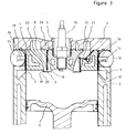
- the assymetric two stroke engine see Figure 3, consists of a piston 1 moving reciprocally in a cylinder 2.
- the piston 1 is mechanically connected in known manner to a drive shaft, not shown.
- Cylinder 2 is capped by a cylinder head comprising an upper part 3 and lower part 4 clamped together by a hollow bolt 5.
- Annular inlet and exhaust valves 6 and 7 together with inlet and exhaust ports 8 and 9 respectively are arranged broadly in concentric fashion around a spark plug 10.
- the exhaust valve 7 is sealed on its lower outer edge in the closed position by an exhaust seat 11, aided by valve springs (not shown).
- the exhaust valve 7 is modulated by an actuator.
- Solenoids, 12 and 13 are shown acting on valve plates 14 and 15 respectively.
- Magnetic forces of attraction are created on solenoid faces 16 and 17 when an electric current is passed through the windings of the solenoids 12 and 13.
- the magnetic force of attraction causes the exhaust valve 7 to lift and uncover the exhaust port 9.
- the electric current passed through the solenoids 12 and 13 may be varied in timing and duration in order to modulate the exhaust period according to engine operating conditions.
- the exhaust valve modulation may be used to control the timing of a negative pressure pulse in the cylinder during the scavange stroke.
- the annular inlet valve 6 comprises an inner seat 18 and outer seat 19 which may be masked by a lip 20 or similar device to control differentially flow across the seats, to assist, for example phase segregation or charge stratification.
- a plurality of pretension springs 21 act on the inlet valve via legs 22.
- the annular inlet port 8 may contain charge at atmospheric pressure or pressurized charge from an external source.
- the inlet valve 6 may have supports 23 to limit maximum stress due to combustion pressure and the supports may also provide fuel admission means from a fuel rail 24. They may be shaped as guide vanes to generate swirl in the combustion chamber.
- the inlet valve 6 is designed to open (downwards) under the influence of negative cylinder pressure.
- modulation of the exhaust valve 7 may be used to control the charge filling process and therefore attract volume of charge and the effective compression ratio. Intake throttling may be eliminated and exhaust valve modulation used as a means of load control.
- the wall thickness of the annular exhaust valve 7 may be selected such that the hoop stress generated by the combustion pressure increases the valve diameter and effects a seal against the cylinder wall.
- Further controls may be exercised in order to modulate engine load or engine output.
- the air/fuel ratio may be varied as in the Diesel engine.
- the annular inlet valve 6 is particularly appropriate in producing a stratified charge with, for example, a rich central mixture being admitted across the inner valve seat 18 and a weak mixture across the outer valve seat 19.
- the charge density may be varied as in the Otto engine, but not by means of intake throttling, rather by regenerative heating from the exhaust.
- a heat exchanger may be used with control means to vary the proportion of charge heating according to the required load.
- performance may be modulated by control of cycle frequency. Cylinders may be cut out in order to operate them at higher load, they for example fire every four or six strokes rather than every two.
- An alternative method of operating the exhaust valve may use a mechanical linkage in place of the solenoids. This may be praticularly suitable for high speed high power engines. Such engines may be spark ignition or compression ignition types.
- the assymetric cycle has been described in relation to an engine in which one of the engine strokes is used to carry out a compression phase.
- a second case exists in which the compression is carried out predominantly externally.
- the precompressed charge may be admitted close to top dead centre quickly followed by ignition, combustion and expansion.
- the pressure/volume diagram for the external compression case is shown in Figure 4.
- Induction is carried out between points i - j in compressor 31 followed by compression between j - k and discharge between k - l to receiver 32 via tapping M.
- the receiver 32 may be of the through flow design with a separate entry and exit.
- a charge may be heated, point n, in a heat exchanger 33.
- the charge is admitted to an engine 34 between points o - p and mixed with the fuel and ignited.
- Combustion occurs between points p-q-r followed by expansion between r - s.
- Exhaust occurs between s-t-u.
- the compressor may be driven from the engine intermittently as required
- the assymetric external compression engine exhibits higher work ratios than the assymetric internal compression engine (AIC), for a given compression ratio. This relates to the additional discharge work from the compressor. As a result the AEC optimises at lower compression ratios. It has a low iding speed capability and fast response due to the charge receiver. Using variable valve timing the engine may be transformed into a compressor, discharging compressed air to the charge receiver to provide regenerative vehicle braking. The AEC engine is better able to utilise a regenerative charge heating from the exhaust via the modulated heat exchanger 33, than the AIC engine as heating can be applied after compression.
- Figure 5 shows the effect of the port load density modulation, by means of regenerative heating h, on raising thermal efficiency of an AEC engine. Inefficient light load operation is avoided by the use of frequency control to cut out cylinders.
- the AEC engine carries out compression in a cool cylinder with resultant potential of reducing peak cycle temperature and hence nitrogen oxide emissions.
- the charge is admitted to the engine cylinder around top dead centre and requires rapid mixing of the finely prepared fuel spray in order to start combustion early in the expansion stroke and complete it quickly.
- High inlet velocity is the key to achieving a short combustion phase.
- Admission of the pre-compressed charge into the clearance volume combustion space occurs initially at sonic velocity.
- Multiple stage compression may be used in which a final compression stage occurs in the engine cylinder. This would be the likely construction for a compression ignition version.
- FIG. 6 An alternative cylinder head arrangement, see Figure 6, uses a number of inlet valves 40 and exhaust valves 41 in annular formation.
- a differential area may be employed on the inlet valves to impart a normally closed position on the valve by means of charge pressure in place of valve springs. This is achieved using diaphragms 42, 43, 44 and 45 of larger diameter than the valve seat port 46.
- a heat exchange process between an inlet passage 47 and an exhaust passage 48 may be used to raise intake temperature.
- a valve means may be introduced to modulate the heat exchange process.
- the exhaust valves may be operated in the conventional manner using return spring 49.
- Figure 7 shows the detailed construction of a positive displacement machine in a V-twin configuration.
- a stepped disc pair 52 converts linear to rotary motion in both cylinder lines. The disc is shown with circumferential material removed to reduce weight and frictional area.
- Inner and outer roller element bearings 53, 54 respectively are integrated into the stepped disc contact surfaces to reduce further the friction.
- the mechanism comprises reciprocating members 55 and 56 attached via the stepped disc to a crank pin 57 of rotating members 58 and 59 which supported in bearings 60, 61 and 62 located in a sleeve 63 and a crank case 64 which supports cylinders 65 and 66 together with cylinder heads 67 and 68. Assembly is facilitated by the use of a split crank shaft retained by a bolt 69, the sleeve 63 and removeable cylinders 65 and 66.
- a plug 70 seals the crank case 64 and the crank shaft supports a flywheel 71 which counter- balances the inertia forces acting at the crank pin to achieve a complete balance of forces. A small couple is unresolved.
- the disc eccentricity is equal to the crank throw.
- the crank throw is equal to only one quarter of the stroke.
- the motion of the disc is one of planetary rotation about the crank pin at equal speed in the opposite direction.
- a pair of reciprocating members are required in order to share the forces between the cylinder lines and avoid excessive side forces being generated that would otherwise jam the mechanism.
- the side force is proportional to the tangent of the crank shaft angle.
- Phasing constraint is provided by way of example by reciprocator yoke guides 72, 73, 74 and 75.
- the recipricator is then so well constrained that the mechanism has little capability to accomodate out of tolerance conditions.
- the phasing constraint is applied about the disc axis, to rear circular recipricator yokes 76, 77.
- the reciprocator can swivel about the axis of the stepped disc to accomodate, for example, a misaligned cylinder.
- Rolling element bearings may also be used to locate the yoke in its guide.
- Figure 8 is used to demonstrate various power modulation scenarios within an integrated solution.
- Pistons, 100, 101 are attached to yokes 102. 108 respectively. Both yokes are attached to a connecting disc pair 104.
- This may be constructed of two or more parts bolted together or a single piece.
- the cylinders 105, 106 are angled in a V formation at 90° to each other.
- a crank pin 107 is part of a crankshaft 108 which may comprise a number of parts bolted together according to the number of cylinder banks to increase crank shaft stiffness and facilitate assembly.
- a section is shown through a V6 engine. The throw of the crankshaft is normally equal to the throw of the connecting disc 104.
- the connecting disc 104 rotates about the crank pin 107 at a constant angular velocity in the opposite direction to the crank shaft 108.
- the yokes 102 and 103 impart a simple harmonic recipricatory motion to the pistons along the axis of the cylinder centre line.
- a constant centrifugal force is generated in the direction of the crank pin equal to the mass of one piston/disc assembly.
- the inlet and exhaust valve timing is independently variable (not illustrated). This enables each cylinder to function as either a compressor or an expander. In the unsealed cylinder mode the piston functions simply as a counterweight. Hence inefficient light load operation may be avoided by running fewer power cylinders and more compressor cylinders or cutting out some cylinders. The excess compressed air may be stored and subsequently used.
- the section of the V6 engine shows in principle a V-twin engine 109 connected to a V4 engine 110 via a clutch 111. For continuous full load operation the V-twin unit functions as a compressor and the V4 unit functions as a power unit driving the compressor via the clutch. The V-twin is balanced as an independent unit.
- the clutch may be disengaged and the V-twin shut down.
- One or more of the V4 cylinders may take up the compression function as required.
- the V4 unit may be shut down and compression and power functions carried out by the V-twin.
- performance may be varied from six compressor cylinders (regenerative braking) to six power cylinders (temporary performance boost) and any combination between.
- a single compressed air receiver may be used or multiple receivers, for example a low pressure one for powered operation and a high pressure one for regenerative braking.
- Charge heating via an intake/exhaust heat exchanger may be used on the high pressure receiver only, or on any of the other combinations or not at all.
- An intelligent control system would determine an optimum operating regime compatible with the driver input demands.
- the connecting disc mechanism may also be applied to conventional engines.
- a gas generator/air compressor according to the invention has opposing expander and compressor pistons connected by a parallelogram linkage.
- Opposing expander pistons 139 and 140 power opposing compressor pistons 141 and 142 through parallelogram links 143, 144, 145 and 146 enclosed in a cylinder housing 147.
- Each expander piston has an expansion chamber 148 and 149 with inlet valves 150 and 151 together with exhaust valves 152 and 153.
- the compressor pistons 141 and 142 are housed in cylinders having inlet valves 154 and 155 and together with discharge valves 156 and 157.
- Combustion and expansion have started in the expander chambers so that movement of the pistons 139 and 140 through the linkage 143, 144, 145 and 146 causes the compressor pistons 141 and 142 to start a compression cycle.
Landscapes
- Engineering & Computer Science (AREA)
- Mechanical Engineering (AREA)
- General Engineering & Computer Science (AREA)
- Chemical & Material Sciences (AREA)
- Combustion & Propulsion (AREA)
- Physics & Mathematics (AREA)
- Geometry (AREA)
- Output Control And Ontrol Of Special Type Engine (AREA)
Abstract
Description
- This invention relates to internal combustion engines and gas generators together with their method of operation.
- Existing internal combustion engines operate at low thermal efficiencies and the products of the fuel burnt in them, exhaust gases, contain environmentally harmful components. The present invention provides an internal combustion engine with increased efficiency and also a lower level of environmentally harmful exhaust emissions. The engines according to the invention will run on lowly refined, broadcut, fuels.
- The Otto and Diesel engine cycles together with associated means of load control have been used, principally unchanged, for over a century. They are symmetrical cycles (the compression ratio equals the expansion ratio) and hence have low thermodynamic efficiencies. Half of the combustion energy is directly exhausted, heating the environment and providing no useful work.
- As engine load is reduced the efficiency falls even further. At one sixth load the efficiency is halved. The Diesel engine, although avoiding intake throttling pumping loses, suffers high internal friction at part load as a result of the high compression ratio. The work ratio, that is the ratio of the compression work to expansion work, is a useful means of determining the internal efficiency of the engine.
- The Diesel Cycle achieves a higher efficiency than the spark ignition Otto engine as it operates with a higher overall pressure ratio, creating severe noise, vibration and harshness (NVH) concerns as a result.
- Both types of engine modulate the charge load in order to vary output. In the Diesel engine the fuel quantity per cycle is varied while the volume and density of charge air remains substantially constant. Hence, modulation is effected by variable air/fuel ratio. In comparison the Otto engine modulates the air density (throttling) while the charge air volume and air/fuel ratio remains substantially constant. Previous work by the inventor relates to modulation of the cycle frequency while the load remains substantially constant.
- In terms of exhaust emissions the Otto and Diesel Cycles show an inherent conflict between efficiency and low nitrogen oxide (NOx) emissions. High expansion ratios are required for high efficiency but require high peak combustion temperatures which increase the NOx emissions. Carbon monoxide (CO), carbon dioxide (CO₂) and hydrocarbon emissions arise from the combustion of hydrocarbon fuels. Carbon monoxide and hydrocarbon emissions are the consequence of incomplete fuel combustion and may be reduced by improving combustion control in the engine and the use of weak air/fuel ratios. Hydrocarbon emissions increase at low combustion temperatures. Carbon dioxide emission is directly related to the amount of hydrocarbon fuel consumed and can only be reduced by increasing engine efficiency.
- The proposed strategy for the design of internal combustion engines and gas generators with lowered emissions of environmentally harmful products is as follows:
- To control more precisely pollutant production and harshness in the combustion process and to improve the refinery efficiency
thermodynamic efficiency
combustion efficiency
internal efficiency
modulation efficiency
braking efficiency -
- a. To use a lowly refined wide cut fuel for increased overall efficiency by minimising engine octane requirement.
-
- a. To adopt an assymetric thermodynamic cycle in which a low compression ratio is combined with a high expansion ratio for increased ideal thermal efficiency.
-
- a. To minimise octane requirement by late admission of the fuel into the hot cylinder.
- b. To improve control of the combustion process by initiating combustion in a zone of low turbulence.
- c. To improve control of the combustion process by simplifying the geometry of turbulence-generation.
- d. To increase the speed of combustion and the rate of expansion so that the rate of pressure rise (harshness) is not increased.
- e. To segregate more clearly each thermodynamic phase to achieve better optimumisation.
- f. To moderate the temperature extremes across the combustion chamber.
- g. To simplify the geometry of fuel admission so that stratification is variable in a controlled manner.
-
- a. To optimise the work ratio by the combination of a low compression ratio with a high expansion ratio and hence optimise internal efficiency.
- b. To maximise the use of each engine stroke.
- c. To minimise the mechanical complexity and replace sliding contact by rolling contact where possible.
-
- a. To introduce mass charge load control by modulating the volume of trapped charge.
- b. To introduce charge density load control by preheating the charge air, preferably by regenerative means.
- c. To introduce air/fuel ratio load control by modulating the fuel mass, possibly in combination with stratified charge.
- d. To minimise pumping losses by eliminating intake throttling.
- e. To introduce frequency control by using cylinder cut-out techniques.
- f. To minimise or eliminate idling speed.
- g. To introduce torque boosting to minimise the number of transmission ratios.
- h. To introduce regenerative braking.
- i. To improve response.
-
- a. To reduce carbon dioxide emission by improved total cycle efficiency.
- b. To reduce emissions of nitrogen oxides by using lower initial cycle temperature and low compression ratio to moderate the peak cycle temperature.
- c. To reduce hydrocarbon emissions by higher light load temperatures and higher cylinder wall temperatures.
- d. To reduce hydrocarbon and carbon monoxide and hydrocarbon emissions by lean combustion, possibly aided by stratification.
- e. To reduce warm-up emmissions by use of integral exhaust port catalysts, close coupling being aided by reduced exhaust gas temperatures.
- f. To reduce NVH emissions by adopting engine mechanisms with near perfect balance.
- The present invention provides an internal combustion engine or gas generator in which the refinery, thermodynamic, combustion, internal modulation, and/or braking efficiency is improved.
- According to the present invention there is provided a two-stroke internal combustion engine or gas generator characterised in that the compressor and the expander have assymetric swept volumes.
- In order that the invention may be clearly understood it will now be described with reference to the accompanying drawings in which:
- Figure 1 is a graph showing the relationship between the pressure and the volume during the thermodynamic cycle of an internal combustion engine,
- Figure 2 is a graph showing the relationship between the thermal efficiency and the load for a series of internal internal combustion engines,
- Figure 3 is a schematic drawing of a combustion chamber layout using annular inlet and exhaust valves with a stratified charge,
- Figure 4 is a schematic arrangement of a two-stroke compression ignition engine according to the invention,
- Figure 5 is a graph showing the relationship between the brake thermal efficiency and load of an engine according to the invention contrasted with an engine operating under the conditions of the Otto cycle,
- Figure 6 is a schematic drawing of an alternative combustion chamber layout using annular inlet and exhaust valves with a stratified charge,
- Figure 7 is a schematic arrangement of a multi-cylinder engine according to the invention using an improved means of converting linear to rotary motion,
- Figure 8 is a further schematic arrangement of the multi-cylinder engine shown in Figure 7, and
- Figure 9 is a schematic arrangement of a gas generator/air compressor using a parallelogram linkage.
- The typical pressure/volume characteristics of an internal combustion engine employing compression in the power cylinder will be described with reference to Figure 1. Induction occurs between points a - b, compression between points b - c, near constant volume combustion between c - d and constant pressure combustion between d - e. Expansion occurs between e - f and exhaust between f - g and g - b. Figure 2 shows the computed efficiency of the assymetric cycle over its load range compared to the Diesel cycle and the Otto cycle using similar component efficiencies. The lowest efficiency curve shown represents actual engine test results from a carburetted two valve per cylinder engine with a 9.5:1 expansion ratio. The next solid line represents engine test results from a direct inject diesel engine with an expansion ratio E of 16:1. The simple computer simulation of the Diesel cycle with a 16:1 expansion ratio shows a close correlation. The model assumes constant component and combustion efficiencies across the range, whereas these will vary in practice as shown by the actual efficiency curve. The Diesel cycle was then remodelled for the same 16:1 expansion ratio but with a reduced compression ration to achieve the assymetric cycle according to Figure 1. The efficiency peaks at over 40 per cent with the improvement maintained across the load range. A further increase in expansion ratio, as shown by E=28, shows further improvement at high loads but at some expense to low load efficiency. While the expansion ratio remained fixed for the simulations, the compression ratio was optimised for each condition. The optimum brake thermal efficiency occurs at a midway compression ratio between the optimum compression ratio defined by the ideal efficiency and the optimum compression ratio defined by the condition of optimum work ratio. Component efficiencies are based on work areas above the atmospheric pressure datum.
- The assymetric cycle is not new. Variable valve timing has been employed to delay inlet valve closing in the four stroke engine which allows some of the charge to be pumped back into the inlet manifold in order to trap less charge and so avoid the pumping losses associated with intake throttling. Sophisticated technology is required to control the phasing of the dynamic highly stressed valve components.
- In comparison, the simple ported two-stroke engine only requires the exhaust port to lead the transfer port. This results in a low expansion ration and low efficiency compounded by charge loss into the exhaust port.
- The simplest form of assymetric cycle, according to Figure 1, requires two piston strokes to complete the cycle with expansion predominatly occupying one of the strokes. Hence, induction, compression and exhaust occupy the other stroke. This requires that induction is achieved against a decreasing cylinder volume, that the rate of incoming flow is greater than the rate of volume decrease. A pressure head is required to achieve the differential rate. Either sub-atmospheric cylinder depression has to be created at the end of the exhaust phase, or the charge pressure has to be raised externally, or both. Hence, multiple stages of compression may be used. The assymetric two stroke engine, see Figure 3, consists of a
piston 1 moving reciprocally in acylinder 2. Thepiston 1 is mechanically connected in known manner to a drive shaft, not shown.Cylinder 2 is capped by a cylinder head comprising anupper part 3 andlower part 4 clamped together by ahollow bolt 5. Annular inlet andexhaust valves 6 and 7 together with inlet andexhaust ports spark plug 10. Theexhaust valve 7 is sealed on its lower outer edge in the closed position by anexhaust seat 11, aided by valve springs (not shown). Theexhaust valve 7 is modulated by an actuator. Solenoids, 12 and 13, are shown acting onvalve plates - Magnetic forces of attraction are created on solenoid faces 16 and 17 when an electric current is passed through the windings of the
solenoids exhaust valve 7 to lift and uncover theexhaust port 9. The electric current passed through thesolenoids - The annular inlet valve 6 comprises an
inner seat 18 andouter seat 19 which may be masked by alip 20 or similar device to control differentially flow across the seats, to assist, for example phase segregation or charge stratification. A plurality of pretension springs 21 act on the inlet valve vialegs 22. Theannular inlet port 8 may contain charge at atmospheric pressure or pressurized charge from an external source. The inlet valve 6 may havesupports 23 to limit maximum stress due to combustion pressure and the supports may also provide fuel admission means from afuel rail 24. They may be shaped as guide vanes to generate swirl in the combustion chamber. The inlet valve 6 is designed to open (downwards) under the influence of negative cylinder pressure. Hence, modulation of theexhaust valve 7 may be used to control the charge filling process and therefore attract volume of charge and the effective compression ratio. Intake throttling may be eliminated and exhaust valve modulation used as a means of load control. The wall thickness of theannular exhaust valve 7 may be selected such that the hoop stress generated by the combustion pressure increases the valve diameter and effects a seal against the cylinder wall. - Further controls may be exercised in order to modulate engine load or engine output. In a second means of load modulation the air/fuel ratio may be varied as in the Diesel engine. The annular inlet valve 6 is particularly appropriate in producing a stratified charge with, for example, a rich central mixture being admitted across the
inner valve seat 18 and a weak mixture across theouter valve seat 19. In a third means of load modulation the charge density may be varied as in the Otto engine, but not by means of intake throttling, rather by regenerative heating from the exhaust. A heat exchanger may be used with control means to vary the proportion of charge heating according to the required load. Finally, at light load conditions performance may be modulated by control of cycle frequency. Cylinders may be cut out in order to operate them at higher load, they for example fire every four or six strokes rather than every two. - An alternative method of operating the exhaust valve may use a mechanical linkage in place of the solenoids. This may be praticularly suitable for high speed high power engines. Such engines may be spark ignition or compression ignition types.
- The assymetric cycle has been described in relation to an engine in which one of the engine strokes is used to carry out a compression phase. A second case exists in which the compression is carried out predominantly externally. The precompressed charge may be admitted close to top dead centre quickly followed by ignition, combustion and expansion. The pressure/volume diagram for the external compression case is shown in Figure 4. Induction is carried out between points i - j in
compressor 31 followed by compression between j - k and discharge between k - l toreceiver 32 via tapping M. Alternatively, thereceiver 32 may be of the through flow design with a separate entry and exit. A charge may be heated, point n, in aheat exchanger 33. The charge is admitted to anengine 34 between points o - p and mixed with the fuel and ignited. Combustion occurs between points p-q-r followed by expansion between r - s. Exhaust occurs between s-t-u. The compressor may be driven from the engine intermittently as required via a clutch 35. - The assymetric external compression engine (AEC) exhibits higher work ratios than the assymetric internal compression engine (AIC), for a given compression ratio. This relates to the additional discharge work from the compressor. As a result the AEC optimises at lower compression ratios. It has a low iding speed capability and fast response due to the charge receiver. Using variable valve timing the engine may be transformed into a compressor, discharging compressed air to the charge receiver to provide regenerative vehicle braking. The AEC engine is better able to utilise a regenerative charge heating from the exhaust via the modulated
heat exchanger 33, than the AIC engine as heating can be applied after compression. Figure 5 shows the effect of the port load density modulation, by means of regenerative heating h, on raising thermal efficiency of an AEC engine. Inefficient light load operation is avoided by the use of frequency control to cut out cylinders. The AEC engine carries out compression in a cool cylinder with resultant potential of reducing peak cycle temperature and hence nitrogen oxide emissions. - The charge is admitted to the engine cylinder around top dead centre and requires rapid mixing of the finely prepared fuel spray in order to start combustion early in the expansion stroke and complete it quickly. High inlet velocity is the key to achieving a short combustion phase. Admission of the pre-compressed charge into the clearance volume combustion space occurs initially at sonic velocity.
- Multiple stage compression may be used in which a final compression stage occurs in the engine cylinder. This would be the likely construction for a compression ignition version.
- An alternative cylinder head arrangement, see Figure 6, uses a number of
inlet valves 40 andexhaust valves 41 in annular formation. A differential area may be employed on the inlet valves to impart a normally closed position on the valve by means of charge pressure in place of valve springs. This is achieved usingdiaphragms inlet passage 47 and anexhaust passage 48 may be used to raise intake temperature. A valve means may be introduced to modulate the heat exchange process. The exhaust valves may be operated in the conventional manner usingreturn spring 49. In a further embodiment. Figure 7 shows the detailed construction of a positive displacement machine in a V-twin configuration. A steppeddisc pair 52 converts linear to rotary motion in both cylinder lines. The disc is shown with circumferential material removed to reduce weight and frictional area. - Inner and outer
roller element bearings reciprocating members pin 57 of rotatingmembers bearings sleeve 63 and a crankcase 64 which supportscylinders cylinder heads bolt 69, thesleeve 63 andremoveable cylinders plug 70 seals thecrank case 64 and the crank shaft supports aflywheel 71 which counter- balances the inertia forces acting at the crank pin to achieve a complete balance of forces. A small couple is unresolved. - Normally, the disc eccentricity is equal to the crank throw. Hence, the crank throw is equal to only one quarter of the stroke. The motion of the disc is one of planetary rotation about the crank pin at equal speed in the opposite direction. A pair of reciprocating members are required in order to share the forces between the cylinder lines and avoid excessive side forces being generated that would otherwise jam the mechanism. In a simple line mechanism the side force is proportional to the tangent of the crank shaft angle. When each disc is constrained to motion along each cylinder line, simple harmonic motion is produced and the recipricator, connecting member and rotary member are correctly phased.
- Phasing constraint is provided by way of example by reciprocator yoke guides 72, 73, 74 and 75. Prior art by Baker of Esso in Abingdon Cross engine, 1974 I. Mech. E. Proc.. Vol 188. 38/74, used double ended cylinders in the two lines to form an X configuration and provide the necessary phasing constraint. However, the recipricator is then so well constrained that the mechanism has little capability to accomodate out of tolerance conditions.
- In this proposal the phasing constraint is applied about the disc axis, to rear circular recipricator yokes 76, 77. Hence, the reciprocator can swivel about the axis of the stepped disc to accomodate, for example, a misaligned cylinder. Rolling element bearings may also be used to locate the yoke in its guide.
- In a further embodiment Figure 8 is used to demonstrate various power modulation scenarios within an integrated solution. Pistons, 100, 101 are attached to yokes 102. 108 respectively. Both yokes are attached to a connecting
disc pair 104. This may be constructed of two or more parts bolted together or a single piece. Ideally thecylinders crank pin 107 is part of acrankshaft 108 which may comprise a number of parts bolted together according to the number of cylinder banks to increase crank shaft stiffness and facilitate assembly. A section is shown through a V6 engine. The throw of the crankshaft is normally equal to the throw of the connectingdisc 104. The connectingdisc 104 rotates about thecrank pin 107 at a constant angular velocity in the opposite direction to the crankshaft 108. Hence, theyokes 
- In the V6 engine shown the inlet and exhaust valve timing is independently variable (not illustrated). This enables each cylinder to function as either a compressor or an expander. In the unsealed cylinder mode the piston functions simply as a counterweight. Hence inefficient light load operation may be avoided by running fewer power cylinders and more compressor cylinders or cutting out some cylinders. The excess compressed air may be stored and subsequently used. The section of the V6 engine shows in principle a V-
twin engine 109 connected to aV4 engine 110 via a clutch 111. For continuous full load operation the V-twin unit functions as a compressor and the V4 unit functions as a power unit driving the compressor via the clutch. The V-twin is balanced as an independent unit.black dots 112 denoting counterweights, and the V4 as another independent unit. At part load the clutch may be disengaged and the V-twin shut down. One or more of the V4 cylinders may take up the compression function as required. At light load the V4 unit may be shut down and compression and power functions carried out by the V-twin. Hence, by variable valve timing, performance may be varied from six compressor cylinders (regenerative braking) to six power cylinders (temporary performance boost) and any combination between. - A single compressed air receiver may be used or multiple receivers, for example a low pressure one for powered operation and a high pressure one for regenerative braking. Charge heating via an intake/exhaust heat exchanger may be used on the high pressure receiver only, or on any of the other combinations or not at all. An intelligent control system would determine an optimum operating regime compatible with the driver input demands. The connecting disc mechanism may also be applied to conventional engines.
- A gas generator/air compressor according to the invention. see Figure 9, has opposing expander and compressor pistons connected by a parallelogram linkage. Opposing
expander pistons compressor pistons parallelogram links expansion chamber inlet valves exhaust valves 152 and 153. Thecompressor pistons inlet valves discharge valves - In the first phase of the compression cycle, see Figure 9a, the intake mixture has been admitted to both the
expander chambers inlet valves - Combustion and expansion have started in the expander chambers so that movement of the
pistons linkage compressor pistons - When compression is complete, see Figure 9b, the compressed air is released through
discharge valves pistons piston rods Inlet valves expander pistons linkage valves 152 and 153.
Claims (22)
- A two-stroke internal combustion engine or gas generator characterised in that the compressor and the expander have assymetric swept volumes.
- An internal combustion engine or gas generator according to claim 1, characterised in that the reflected exhaust pulse is modulated to control the induction phase and hence the effective compressor swept volume.
- An internal combustion engine or gas generator according to claim 1, characterised in that the inlet valve phasing is modulated to control the effective compressor swept volume.
- An internal combustion engine or gas generator according to claim 1, characterised in that compression is substantially completed prior to admission of the charge to the combustion chamber.
- An internal combustion engine or gas generator according to claim 1, characterised in that a charge receiver is provided for storage of the charge medium.
- An internal combustion engine or gas generator according to claim 1, characterised in that it includes a compressor or similar charge preparation means which is regulated independently of the engine.
- An internal combustion engine or gas generator according to claim 1, characterised in that at least one cylinder may be changed from functioning as an expander to functioning as a compressor by means of variable valve timing.
- An internal combustion engine or gas generator according to claim 1, characterised in that compression means provides multiple stage compression wherein the final stage may be completed in the cylinder in which combustion takes place.
- An internal combustion engine or gas generator according to claim 1, characterised in that heat transfer means (33) are included between the compression means and the combustion means to effect heat transfer from the exhaust gases to the intake gases.
- An internal combustion engine or gas generator according to claim 1, characterised in that power modulation is effected by control of charge density.
- An internal combustion engine or gas generator according to claim 1, characterised in that power modulation is effected by control of cycle frequency by means of cylinder cut-out.
- An internal combustion engine or gas generator according to claim 1, characterised in that the engine has a plurality of cylinders and power modulation is effected by decoupling of one or more engine cylinders.
- An internal combustion engine or gas generator according to claim 1, characterised in that power modulation is effected by means of stratified charge mixture control.
- An internal combustion engine or gas generator according to claim 1, characterised in that it has a cylinder with an inlet port (8) having a substantially annular configuration.
- An internal combustion engine or gas generator according to claims 13 and 14, characterised in that it includes means (18,19) for selective masking of the annular valve seats to effect differential flow characteristics.
- An internal combustion engine or gas generator according to claim 1, characterised in that it has a cylinder with an exhaust port (9) having a substantially annular configuration.
- An internal combustion engine or gas generator according to claim 16, characterised in that the exhaust port ( ) has a valve (7) of annular configuration.
- An internal combustion engine or gas generator according to claim 1, characterised in that it has a cylinder providing annular segregation of intake and exhaust functions.
- An internal combustion engine or gas generator according to claim 16, characterised in that the exhaust port (9) has a valve of thin cylindrical construction having sufficient flexibility that the annular exhaust port (9) is effectively sealed under cylinder pressure whilst under exhaust conditions clearance returns to allow free exhaust valve operation.
- An internal combustion engine or gas generator according to claim 1, characterised in that an eccentric contra-rotating disc (52,104) is used as a connecting member between reciprocating and rotating members and in that phasing constraint guides (72,73,74,75) accomodate angular misalignment of the piston with respect to the crankshaft whilst controlling the path of the piston yoke (76,77).
- An internal combustion engine or gas generator according to claim 20, characterised in that it has a plurality of cylinders in V configuration and a stepped disc connecting member (52) common to both cylinder rows.
- An internal combustion engine or gas generator according to claim 1, characterised in that it has a parallelogram linkage (143,144,145,146) connecting expansion and compression pistons (139,140,141,142).
Applications Claiming Priority (4)
| Application Number | Priority Date | Filing Date | Title |
|---|---|---|---|
| GB909028092A GB9028092D0 (en) | 1990-12-27 | 1990-12-27 | Internal combustion engines |
| GB9028092 | 1990-12-27 | ||
| GB919105100A GB9105100D0 (en) | 1990-12-27 | 1991-03-11 | Internal combustion engines |
| GB9105100 | 1991-03-11 |
Publications (2)
| Publication Number | Publication Date |
|---|---|
| EP0493135A1 true EP0493135A1 (en) | 1992-07-01 |
| EP0493135B1 EP0493135B1 (en) | 1996-12-04 |
Family
ID=26298183
Family Applications (1)
| Application Number | Title | Priority Date | Filing Date |
|---|---|---|---|
| EP91312072A Expired - Lifetime EP0493135B1 (en) | 1990-12-27 | 1991-12-27 | Internal combustion engines |
Country Status (2)
| Country | Link |
|---|---|
| EP (1) | EP0493135B1 (en) |
| DE (1) | DE69123438T2 (en) |
Cited By (7)
| Publication number | Priority date | Publication date | Assignee | Title |
|---|---|---|---|---|
| WO1997035104A1 (en) * | 1996-03-20 | 1997-09-25 | Starodetko Evgeny Alexandrovic | Free piston engine and method of operating |
| EP1092851A3 (en) * | 1999-10-13 | 2002-04-17 | Heinzle, Friedrich | Internal combustion engine and method of operating |
| WO2002073016A1 (en) * | 2001-03-14 | 2002-09-19 | Marimuthu Ramu Thiyagarajan | A low cost new compression ignition internal combustion engine and method of operating said engine with increased mechanical and thermal efficiency |
| EP1314862A2 (en) | 2001-11-22 | 2003-05-28 | HALL, Keith Gordon | Electromagnetic valve actuator |
| RU2214525C2 (en) * | 2000-04-18 | 2003-10-20 | Константин Евгеньевич Стародетко | Method of operation of power plant with piston internal combustion engine (versions) and power plant for implementing the method |
| GB2434405A (en) * | 2006-01-20 | 2007-07-25 | Keith Gordon Hall | Internal combustion engine with disc drive mechanism and crankcase compression of intake air |
| GB2512423A (en) * | 2012-12-08 | 2014-10-01 | Keith Gordon Hall | Disc-Drive Mechanisms |
Citations (5)
| Publication number | Priority date | Publication date | Assignee | Title |
|---|---|---|---|---|
| US4386587A (en) * | 1981-12-21 | 1983-06-07 | Ford Motor Company | Two stroke cycle engine with increased efficiency |
| WO1987003043A1 (en) * | 1985-11-06 | 1987-05-21 | Melchior Jean F | Improvement to two stroke internal combustion engines and implementation method |
| US4798184A (en) * | 1986-11-17 | 1989-01-17 | Sandor Palko | Extended expansion diesel cycle engine |
| US4945869A (en) * | 1989-06-21 | 1990-08-07 | General Motors Corporation | Two cycle crankcase variable inlet timing |
| EP0396325A1 (en) * | 1989-04-26 | 1990-11-07 | Isuzu Ceramics Research Institute Co., Ltd. | Variable-cycle engine |
-
1991
- 1991-12-27 EP EP91312072A patent/EP0493135B1/en not_active Expired - Lifetime
- 1991-12-27 DE DE69123438T patent/DE69123438T2/en not_active Expired - Fee Related
Patent Citations (5)
| Publication number | Priority date | Publication date | Assignee | Title |
|---|---|---|---|---|
| US4386587A (en) * | 1981-12-21 | 1983-06-07 | Ford Motor Company | Two stroke cycle engine with increased efficiency |
| WO1987003043A1 (en) * | 1985-11-06 | 1987-05-21 | Melchior Jean F | Improvement to two stroke internal combustion engines and implementation method |
| US4798184A (en) * | 1986-11-17 | 1989-01-17 | Sandor Palko | Extended expansion diesel cycle engine |
| EP0396325A1 (en) * | 1989-04-26 | 1990-11-07 | Isuzu Ceramics Research Institute Co., Ltd. | Variable-cycle engine |
| US4945869A (en) * | 1989-06-21 | 1990-08-07 | General Motors Corporation | Two cycle crankcase variable inlet timing |
Cited By (8)
| Publication number | Priority date | Publication date | Assignee | Title |
|---|---|---|---|---|
| WO1997035104A1 (en) * | 1996-03-20 | 1997-09-25 | Starodetko Evgeny Alexandrovic | Free piston engine and method of operating |
| EP1092851A3 (en) * | 1999-10-13 | 2002-04-17 | Heinzle, Friedrich | Internal combustion engine and method of operating |
| RU2214525C2 (en) * | 2000-04-18 | 2003-10-20 | Константин Евгеньевич Стародетко | Method of operation of power plant with piston internal combustion engine (versions) and power plant for implementing the method |
| WO2002073016A1 (en) * | 2001-03-14 | 2002-09-19 | Marimuthu Ramu Thiyagarajan | A low cost new compression ignition internal combustion engine and method of operating said engine with increased mechanical and thermal efficiency |
| EP1314862A2 (en) | 2001-11-22 | 2003-05-28 | HALL, Keith Gordon | Electromagnetic valve actuator |
| GB2434405A (en) * | 2006-01-20 | 2007-07-25 | Keith Gordon Hall | Internal combustion engine with disc drive mechanism and crankcase compression of intake air |
| EP1811140A3 (en) * | 2006-01-20 | 2008-05-21 | Keith Gordon Hall | Improvements in internal combustion engines |
| GB2512423A (en) * | 2012-12-08 | 2014-10-01 | Keith Gordon Hall | Disc-Drive Mechanisms |
Also Published As
| Publication number | Publication date |
|---|---|
| EP0493135B1 (en) | 1996-12-04 |
| DE69123438T2 (en) | 1997-07-03 |
| DE69123438D1 (en) | 1997-01-16 |
Similar Documents
| Publication | Publication Date | Title |
|---|---|---|
| US6202416B1 (en) | Dual-cylinder expander engine and combustion method with two expansion strokes per cycle | |
| US6035637A (en) | Free-piston internal combustion engine | |
| US4159700A (en) | Internal combustion compound engines | |
| EP3022411B1 (en) | Spool shuttle crossover valve in split-cycle engine | |
| EP3000965A1 (en) | Internal combustion engines | |
| JP2009516801A (en) | Free piston type 4-stroke engine | |
| GB2428450A (en) | Opposed piston i.c. engine with variable timing | |
| US5970924A (en) | Arc-piston engine | |
| US7841308B1 (en) | Rotary valve in an internal combustion engine | |
| US5579734A (en) | Rotary valve internal combustion engine | |
| US5816203A (en) | Rotary valve internal combustion engine | |
| EP0493135A1 (en) | Internal combustion engines | |
| EP0668962B1 (en) | Engine | |
| US6393841B1 (en) | Internal combustion engine with dual exhaust expansion cylinders | |
| US5803039A (en) | Piston-cylinder assembly and drive transmitting means | |
| US8950368B2 (en) | Internal combustion engine and working cycle | |
| GB2264333A (en) | Compound expansion i.c.piston engine. | |
| US5095869A (en) | Apparatus for control of pressure in internal combustion engines | |
| US11365674B2 (en) | Cam-driven radial rotary engine incorporating an HCCI apparatus | |
| GB2183730A (en) | Charging internal combustion reciprocating piston engine | |
| Hall | The Bruntel Planetary Disc Extended Expansion 2-stroke Engine With Variable Valve Control | |
| US20090320794A1 (en) | Novel Internal Combustion Torroidal Engine | |
| US6877476B1 (en) | Internal combustion engine | |
| Bhargav et al. | A Review on Advanced Engines Technology | |
| GB2090910A (en) | I.C. Engine Driving an Hydraulic Turbine |
Legal Events
| Date | Code | Title | Description |
|---|---|---|---|
| PUAI | Public reference made under article 153(3) epc to a published international application that has entered the european phase |
Free format text: ORIGINAL CODE: 0009012 |
|
| AK | Designated contracting states |
Kind code of ref document: A1 Designated state(s): DE ES FR GB IT |
|
| 17P | Request for examination filed |
Effective date: 19921231 |
|
| 17Q | First examination report despatched |
Effective date: 19930413 |
|
| GRAA | (expected) grant |
Free format text: ORIGINAL CODE: 0009210 |
|
| AK | Designated contracting states |
Kind code of ref document: B1 Designated state(s): DE ES FR GB IT |
|
| PG25 | Lapsed in a contracting state [announced via postgrant information from national office to epo] |
Ref country code: ES Free format text: THE PATENT HAS BEEN ANNULLED BY A DECISION OF A NATIONAL AUTHORITY Effective date: 19961204 |
|
| REF | Corresponds to: |
Ref document number: 69123438 Country of ref document: DE Date of ref document: 19970116 |
|
| ITF | It: translation for a ep patent filed | ||
| REG | Reference to a national code |
Ref country code: GB Ref legal event code: 746 Effective date: 19970220 |
|
| ET | Fr: translation filed | ||
| PLBE | No opposition filed within time limit |
Free format text: ORIGINAL CODE: 0009261 |
|
| STAA | Information on the status of an ep patent application or granted ep patent |
Free format text: STATUS: NO OPPOSITION FILED WITHIN TIME LIMIT |
|
| PG25 | Lapsed in a contracting state [announced via postgrant information from national office to epo] |
Ref country code: FR Effective date: 19971030 |
|
| 26N | No opposition filed | ||
| REG | Reference to a national code |
Ref country code: FR Ref legal event code: ST |
|
| REG | Reference to a national code |
Ref country code: FR Ref legal event code: RN |
|
| REG | Reference to a national code |
Ref country code: FR Ref legal event code: FC |
|
| REG | Reference to a national code |
Ref country code: GB Ref legal event code: IF02 |
|
| PGFP | Annual fee paid to national office [announced via postgrant information from national office to epo] |
Ref country code: FR Payment date: 20051129 Year of fee payment: 15 |
|
| PG25 | Lapsed in a contracting state [announced via postgrant information from national office to epo] |
Ref country code: IT Free format text: LAPSE BECAUSE OF NON-PAYMENT OF DUE FEES;WARNING: LAPSES OF ITALIAN PATENTS WITH EFFECTIVE DATE BEFORE 2007 MAY HAVE OCCURRED AT ANY TIME BEFORE 2007. THE CORRECT EFFECTIVE DATE MAY BE DIFFERENT FROM THE ONE RECORDED. Effective date: 20051227 |
|
| PGFP | Annual fee paid to national office [announced via postgrant information from national office to epo] |
Ref country code: DE Payment date: 20051228 Year of fee payment: 15 |
|
| PGFP | Annual fee paid to national office [announced via postgrant information from national office to epo] |
Ref country code: GB Payment date: 20070122 Year of fee payment: 16 |
|
| PG25 | Lapsed in a contracting state [announced via postgrant information from national office to epo] |
Ref country code: DE Free format text: LAPSE BECAUSE OF NON-PAYMENT OF DUE FEES Effective date: 20070703 |
|
| REG | Reference to a national code |
Ref country code: FR Ref legal event code: ST Effective date: 20070831 |
|
| GBPC | Gb: european patent ceased through non-payment of renewal fee |
Effective date: 20071227 |
|
| PG25 | Lapsed in a contracting state [announced via postgrant information from national office to epo] |
Ref country code: GB Free format text: LAPSE BECAUSE OF NON-PAYMENT OF DUE FEES Effective date: 20071227 |