EP0492967B1 - On-line pellet durability tester - Google Patents
On-line pellet durability tester Download PDFInfo
- Publication number
- EP0492967B1 EP0492967B1 EP91311767A EP91311767A EP0492967B1 EP 0492967 B1 EP0492967 B1 EP 0492967B1 EP 91311767 A EP91311767 A EP 91311767A EP 91311767 A EP91311767 A EP 91311767A EP 0492967 B1 EP0492967 B1 EP 0492967B1
- Authority
- EP
- European Patent Office
- Prior art keywords
- pellets
- pellet
- sample
- test chamber
- durability
- Prior art date
- Legal status (The legal status is an assumption and is not a legal conclusion. Google has not performed a legal analysis and makes no representation as to the accuracy of the status listed.)
- Expired - Lifetime
Links
Images
Classifications
-
- G—PHYSICS
- G01—MEASURING; TESTING
- G01N—INVESTIGATING OR ANALYSING MATERIALS BY DETERMINING THEIR CHEMICAL OR PHYSICAL PROPERTIES
- G01N3/00—Investigating strength properties of solid materials by application of mechanical stress
- G01N3/56—Investigating resistance to wear or abrasion
- G01N3/565—Investigating resistance to wear or abrasion of granular or particulate material
Definitions
- This invention relates to pellet durability testing.
- the invention relates to a device for testing the durability of pellets while in another aspect, the invention relates to a method of testing the durability of pellets, particularly uncured pellets.
- Pellets here defined as an aglomeration (however formed, e.g. by pellet mill, extruder, etc.) of individual ingredients (typically ground ingredients), or a mixture of such ingredients or their equivalents, are a convenient form for a variety of products, e.g. animal feeds, pharmaceuticals, dietary supplements, water treatments, etc. Pellets offer ease of handling from manufacture through consumption, and allow considerable freedom in functional design, e.g. nutritional composition, size, shape, and the like.
- the determination of pellet durability is most desirably made shortly after the pellet is formed such that if the durability of the pellet is found to be poor, then one or more process parameters, such as increasing or decreasing the amount of binder, steam, compaction pressure, etc., can be adjusted immediately to bring pellet durability into compliance with a desired specification.
- process parameters such as increasing or decreasing the amount of binder, steam, compaction pressure, etc.
- Such an on-line testing device should be able to perform the test quickly, efficiently and repeatedly over the course of a production run.
- the testing device should be readily adaptable to existing pellet manufacturing equipment and procedures.
- GB-A-2181559 discloses a pellet durability tester in which pellets to be tested enter a test chamber from the pellet production line via a chute and the test chamber and pellets are weighed. The pellets are then vigorously agitated by blower or compressed air and broken pellets pass through a sieve disc and out of the tester. The test chamber and pellets are re-weighed and the difference in weight before and after agitation is used to calculate the pellet durability.
- US 4633712 discloses an apparatus for determining the mechanical properties of particulate material.
- An inner cylindrical member rotates within an outer cylindrical member to pulverise particulate material (coal).
- a blade can be fitted to protrude into the pulverising chamber.
- Mechanical properties are determined by measuring the torque transmitted from one cylindrical member to the other, and by examining the wear characteristics of the blade.
- the present invention provides a process for measuring the durability of freshly formed, uncured pellets, which comprises introducing a sample of pellets by an all-at-once method of entry into a test chamber; characterised in that the test chamber is equipped with a rotating blade for breaking the pellets into pellet fines and pellet fragments, and that the process further comprises
- the measured power requirement is an amperage draw on an electric motor which is attached to means for driving the rotating blade within the test chamber.
- the measurement of the pellet disintegration can be used without modification as the pellet durability measure, or it can be converted to an existing durability standard, such as the K-State Pellet Quality Test.
- the elapse of time measured in step (3) is the measure of the durability of the sample of pellets disintegrated within the chamber, and preferably this elapse of time is converted to an existing pellet durability index.
- the invention further provides a pellet durability tester suitable for use in a process according to the invention, which comprises
- the process and pellet durability tester of this invention can provide quick, efficient and repeated durability measurements of pellets within moments of their manufacture. This in turn allows changes to be made to one or more of the manufacturing parameters while the process is still in progress. Accordingly the invention also provides a process for manufacturing pellets, in which freshly formed, uncured pellets are manufactured in a pellet mill; the durability of a sample of said pellets is measured by the measuring process according to the invention; and one or more manufacturing process parameters are adjusted immediately to bring pellet durability into compliance with a desired specification.
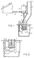
- Figure 1 is a side view and cross-section of one embodiment of a pellet durability tester suitable for performing the process of this invention.
- Figure 2 is a side view and cross-section of the test chamber of the pellet durability tester of Figure 1.
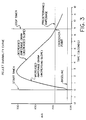
- Figure 3 is an illustrative pellet durability curve.
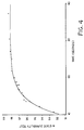
- Figure 4 is an illustrative curve showing the correlation between a durability measure of this invention (time) and the K-State Pellet Quality Test.
- an on-line pellet durability tester comprises an optional sample inlet chamber 10 attached to a test chamber 11 enclosed within a housing 12.
- Door 12a on housing 12 allows access to test chamber 11.
- the inlet chamber 10 has an entrance port 13 and an exit port 14, the latter of which is in open communication with test chamber 11.
- Port 14 is equipped with a gate 15 that when in the closed position, will retain a sample of pellets within inlet chamber 10 and when in the open position, will discharge the pellets from inlet chamber 10 into test chamber 11.
- Gate 15 can be positioned at any point along the length of inlet chamber 10 that is convenient to the operation of the pellet durability tester.
- Entrance port 13 can also be equipped with a gate (not shown) if desired to regulate the intake of pellets from a pellet mill or any other source to inlet chamber 10.
- Test chamber 11 is equipped with a floorgate 16 and a blade 17, the latter of which is connected to a rotor 18.
- Floorgate 16 in the closed position retains pellet samples within test chamber 11 and in the open position, discharges the contents of the test chamber, e.g. pellets, pellet fragments and pellet fines, into housing 12.
- the opening and closing of floorgate 16 is effected by movement of lever 19 which can be manually or automatically operated.
- Figure 2 illustrates floorgate 16 in both the open and closed positions.
- test chamber 11 can vary, as can the size, shape and materials of construction of blade 17, rotor 18, inlet chamber 10 and housing 12.
- test chamber 11 is a cylinder concentrically fitted within housing 12, which is also a cylinder, and attached to the top wall of housing 12.
- Housing 12 itself is optional and the position of the test chamber within the housing can also vary to convenience.
- test chamber 11 is constructed of a durable screen arterial, the size, shape and number of holes of which can vary.
- Floorgate 16 is constructed of similar material, while inlet chamber 10 and housing 12 are constructed of nonporous material.
- Rotor 18 is connected to an electric motor 20 which in turn is connected to a control panel 21 by cable 22 which is typically electric and typically includes signal, sensing, etc., means.
- cable 22 usually includes or is connected to means for sensing the amperage draw of motor 20 and for communicating this information back to control panel 21.
- Control panel 21 can be equipped with a variety of accessories, such as a timer or clock, and it can be either fixed to or an integral part of or located totally apart from housing 12. Its ultimate location with respect to the pellet durability tester is a function of convenience.
- the pellet durability tester of Figure 1 is situated in conjunction with a pelleting mill in such a manner that a sample of freshly milled pellets can be collected, either manually or automatically, directly into sample inlet chamber 10 through entrance port 13.
- the sample is held within inlet chamber 10 until it is ready to be transferred to test chamber 11.
- the sample is transferred by opening floorgate 15, which causes the pellets to drop into test chamber 11. Transfer is effected by gravity and while the sample is being disintegrated in chamber 11, a new sample can be collected into inlet chamber 10.
- the sample entry into test chamber 11 from sample inlet chamber 10 is preferably an all-at-once method of entry as opposed to a metered flow method of entry. The same method of entry is used for all samples tested.
- Pellet fines and fragments will be discharged from test chamber 11 through the holes of the mesh defining its volume and as this occurs, the main drive amperage will begin to gradually decrease (the decreasing slope of the durability curve).
- the dynamic amperage i.e. the amperage above the baseline, is continually checked against a predetermined setpoint amperage which is greater than the baseline amperage (i.e. the line above and parallel to the baseline in Figure 3).
- a predetermined setpoint amperage which is greater than the baseline amperage (i.e. the line above and parallel to the baseline in Figure 3).
- This crossover point can occur virtually anywhere along the decreasing slope of the durability curve, including the point at which it rejoins the baseline, but is typically chosen at or near a point along this part of the curve where the highest correlation with pellet durability is obtained (as experimentally determined).
- the decreasing slope is relatively gradual as compared to the increasing slope and as such, considerably more time is required for :he curve to return to the baseline than to reach its apex.
- Information derived from the tail of the decreasing slope of the curve is usually of marginal or no value relative to pellet durability and as such, can be disregarded.
- the time (or other measure of pellet disintegration) required to reduce the dynamic amperage to the same or less than the predetermined amperage can be used without modification as a durability measure of the pellets or it can be converted to an existing durability standard, such as the K-State Pellet Quality Test, through standard regression analysis techniques.
- a pellet durability tester of substantially the same configuration as that described in Figures 1 and 2 was positioned next to a pellet mill such that sample batches of pellets were diverted from the mill to the tester for durability analysis.
- the sample inlet chamber was constructed of 12 guage steel pipe with an internal diameter of 76,2mm (3 ⁇ ).
- the test chamber was housed in a cylindrical, steel container of 25,4cm (10 ⁇ ) diameter x 25,4cm (10 ⁇ ) height dimensions and fitted with a door of 14,2cm (5.6 ⁇ ) x 12,95cm (5.1 ⁇ ) dimensions which gave access to the test chamber.
- the test chamber was a 76,2mm (3 ⁇ ) internal diameter, 63,5mm (2-1/2 ⁇ ) deep steel screen basket with a steel screen floorgate, all screen size holes measuring 3,57mm (9/64 ⁇ ) in diameter.
- the electric motor that drove the rotor and blade was a 1/8 hp Dayton, 115 vac, 1.8 amp, 3600 rpm, counterclockwise rotation, Model 3M292A.
- the rotor was a 6,35mm (1/4 ⁇ ) driveshaft and the blade was a 6,35mm (1/4 ⁇ ) diameter, 69,85mm (2-3/4 ⁇ ) length, bar with rounded edges.
- a constant, continuous power supply was delivered to the motor through the use of a constant voltage transformer and a variable autotransformer.
- the motor was connected to a control panel equipped with microprocessor/electronic monitoring equipment that included transducers, capacitors and a processor with digital and analog IO capabilities.
- an unscreened sample of about 200 g of animal feed pellets was transferred from the pellet mill to the sample inlet chamber by way of the inlet chamber entrance port.
- the weight of the sample was recorded manually but this operation can be automated simply by attaching a weight sensor to the sample inlet chamber floor (e.g. gate 15) and connecting it to the microprocessor on the control panel.
- a baseline main drive amperage level was automatically recorded from the electric motor.
- the sample was then introduced into the test chamber by an "all-at-once" method of entry.
- the blade was rotating within the test chamber at about 3600 rpm in an unloaded condition.
- Introduction of the sample resulted in a decrease of rpm requiring an additional motor amperage draw in an attempt to maintain its preload rotation.
- a timer was automatically initiated.
- the sample within the test chamber was disintegrated by the action of the blade upon the pellets and the pellets upon themselves and against the chamber walls until the pellets were reduced to pellet fines and pellet fragments that could pass through the holes of the chamber wall and floor.
- the amperage to the main drive under load conditions i.e. the dynamic amperage
- This dynamic amperage was continually checked against a predetermined amperage greater than the baseline amperage, a value that is a function of the nature of the pellets and the test conditions and equipment. In this example, an average of about 70 milliamps above baseline amperage was desirable.
- the dynamic average equalled or was less than the predetermined amperage (i.e.
- the timer was terminated and the total elapsed time on the timer was recorded.
- the floorgate of the test chamber was opened to discharge the sample remains, the floorgate was subsequently closed, and the test chamber was then ready to proceed with the analysis of the next sample.
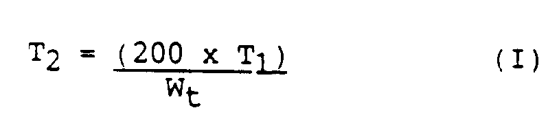
- the test time was then adjusted to a 200 g sample basis using the following equation: where T2 is the adjusted test time, T1 is the test time, and W t is the sample weight in grams.
- T2 is the adjusted test time
- T1 is the test time
- W t is the sample weight in grams.
- the adjusted test time (T2) was then converted to a desired conventional quality scale, here the K-State Pellet Durability Test.
- the equation describing the relationship between the adjusted test time (T2) and the K-State Pellet Durability Index (PDI) was where
Landscapes
- Immunology (AREA)
- Pathology (AREA)
- Life Sciences & Earth Sciences (AREA)
- Chemical & Material Sciences (AREA)
- Analytical Chemistry (AREA)
- Biochemistry (AREA)
- General Health & Medical Sciences (AREA)
- General Physics & Mathematics (AREA)
- Health & Medical Sciences (AREA)
- Physics & Mathematics (AREA)
- Sampling And Sample Adjustment (AREA)
- Investigating Strength Of Materials By Application Of Mechanical Stress (AREA)
- Processing And Handling Of Plastics And Other Materials For Molding In General (AREA)
- Encapsulation Of And Coatings For Semiconductor Or Solid State Devices (AREA)
- Die Bonding (AREA)
- Investigating Or Analysing Biological Materials (AREA)
- Solid-Sorbent Or Filter-Aiding Compositions (AREA)
Abstract
Description
- This invention relates to pellet durability testing. In one aspect, the invention relates to a device for testing the durability of pellets while in another aspect, the invention relates to a method of testing the durability of pellets, particularly uncured pellets.
- Pellets, here defined as an aglomeration (however formed, e.g. by pellet mill, extruder, etc.) of individual ingredients (typically ground ingredients), or a mixture of such ingredients or their equivalents, are a convenient form for a variety of products, e.g. animal feeds, pharmaceuticals, dietary supplements, water treatments, etc. Pellets offer ease of handling from manufacture through consumption, and allow considerable freedom in functional design, e.g. nutritional composition, size, shape, and the like.
- Because pellets are usually subjected to a considerable amount of jostling from the time of their manufacture to the time of their ultimate consumption or use, and because many end uses require or have a preference for pellets with good structural integrity, such as many dry animal feed products, durability is an important physical property of the pellet. Durability, i.e. the resistance of a pellet to significant deterioration over time, can be measured by a variety of different tests, the K-State Pellet Quality Test for animal feed products being representative. This test is described in detail at pages 528-9 of
Section 6 of Appendix F to Feed Manufacturing Technology, published by the Feed Production Council of the American Feed Manufacturers Association (1976). While this and similar tests provide a useful durability measure for a pellet, here an animal feed pellet, the principal disadvantage of these tests are that they are performed on cured pellets, i.e. pellets that have been collected, dried, cooled and/or screened. By the time these steps have been completed, a production run, often measured in tons of product, has been completed and if the pellet durability is poor, then the pellets of that production run must either be reprocessed or disposed as off-specification product. This is particularly true of extruded pellets where considerable time can elapse between pellet formation, usually at elevated temperature, pressure and water content (an uncured state), and the measurement of durability of a hard, dry pellet (finished product or cured state). - As such, the determination of pellet durability is most desirably made shortly after the pellet is formed such that if the durability of the pellet is found to be poor, then one or more process parameters, such as increasing or decreasing the amount of binder, steam, compaction pressure, etc., can be adjusted immediately to bring pellet durability into compliance with a desired specification. Such an on-line testing device should be able to perform the test quickly, efficiently and repeatedly over the course of a production run. In addition, the testing device should be readily adaptable to existing pellet manufacturing equipment and procedures.
- GB-A-2181559 discloses a pellet durability tester in which pellets to be tested enter a test chamber from the pellet production line via a chute and the test chamber and pellets are weighed. The pellets are then vigorously agitated by blower or compressed air and broken pellets pass through a sieve disc and out of the tester. The test chamber and pellets are re-weighed and the difference in weight before and after agitation is used to calculate the pellet durability.
- US 4633712 discloses an apparatus for determining the mechanical properties of particulate material. An inner cylindrical member rotates within an outer cylindrical member to pulverise particulate material (coal). A blade can be fitted to protrude into the pulverising chamber. Mechanical properties are determined by measuring the torque transmitted from one cylindrical member to the other, and by examining the wear characteristics of the blade.
- The present invention provides a process for measuring the durability of freshly formed, uncured pellets, which comprises introducing a sample of pellets by an all-at-once method of entry into a test chamber; characterised in that the test chamber is equipped with a rotating blade for breaking the pellets into pellet fines and pellet fragments, and that the process further comprises
- A. disintegrating at least a portion of the pellets within the test chamber by breaking at least a portion of the pellets through the action of said rotating blade upon the pellets, and
- B. measuring the durability of the pellets by :
- (1) measuring a power requirement to rotate the blade within the test chamber at a given rate of revolution per minute prior to the introduction of the sample of pellets,
- (2) measuring the amount of increase in the power requirement necessary to maintain the rotation of the blade at or near its rate of revolutions per minute in step (1) after the introduction of the sample of pellets into the test chamber, and
- (3) measuring the elapse of time from the first increase in power requirement required by the rotating blade after the introduction of the sample of pellets into the test chamber, to the time at which the increased power requirement has reduced to a predetermined level that is greater than or equal to the power level in step (1).
- Preferably the measured power requirement is an amperage draw on an electric motor which is attached to means for driving the rotating blade within the test chamber.
- The measurement of the pellet disintegration, whatever its nature and units, can be used without modification as the pellet durability measure, or it can be converted to an existing durability standard, such as the K-State Pellet Quality Test. Preferably the elapse of time measured in step (3) is the measure of the durability of the sample of pellets disintegrated within the chamber, and preferably this elapse of time is converted to an existing pellet durability index.
- The invention further provides a pellet durability tester suitable for use in a process according to the invention, which comprises
- A. A test chamber in which a sample of pellets can be disintegrated, the chamber equipped with :
- (1) a first port through which the sample of pellets can enter the chamber, and
- (2) a rotatable blade for disintegrating the pellets into pellet fines and pellet fragments
- B. drive means for operating the rotatable blade,
- C. means for measuring the power requirement of the drive means and
- D. a timer adapted to perform in use the function described in step (3) above.
- The process and pellet durability tester of this invention can provide quick, efficient and repeated durability measurements of pellets within moments of their manufacture. This in turn allows changes to be made to one or more of the manufacturing parameters while the process is still in progress. Accordingly the invention also provides a process for manufacturing pellets, in which freshly formed, uncured pellets are manufactured in a pellet mill; the durability of a sample of said pellets is measured by the measuring process according to the invention; and one or more manufacturing process parameters are adjusted immediately to bring pellet durability into compliance with a desired specification.
- Figure 1 is a side view and cross-section of one embodiment of a pellet durability tester suitable for performing the process of this invention.
- Figure 2 is a side view and cross-section of the test chamber of the pellet durability tester of Figure 1.
- Figure 3 is an illustrative pellet durability curve.
- Figure 4 is an illustrative curve showing the correlation between a durability measure of this invention (time) and the K-State Pellet Quality Test.
- Like numerals are employed to designate like parts throughout the drawings. Various items of equipment, such as electrical connections, fittings, and the like, have been omitted from the drawings so as to simplify the description of the pellet durability tester. However, those skilled in the art will realize that such conventional equipment can be employed as desired.
- In Figure 1, one embodiment of an on-line pellet durability tester is shown, and it comprises an optional
sample inlet chamber 10 attached to atest chamber 11 enclosed within ahousing 12. Door 12a onhousing 12 allows access totest chamber 11. Theinlet chamber 10 has anentrance port 13 and an exit port 14, the latter of which is in open communication withtest chamber 11. Port 14 is equipped with agate 15 that when in the closed position, will retain a sample of pellets withininlet chamber 10 and when in the open position, will discharge the pellets frominlet chamber 10 intotest chamber 11.Gate 15 can be positioned at any point along the length ofinlet chamber 10 that is convenient to the operation of the pellet durability tester.Entrance port 13 can also be equipped with a gate (not shown) if desired to regulate the intake of pellets from a pellet mill or any other source toinlet chamber 10. -
Test chamber 11 is equipped with afloorgate 16 and a blade 17, the latter of which is connected to arotor 18.Floorgate 16 in the closed position retains pellet samples withintest chamber 11 and in the open position, discharges the contents of the test chamber, e.g. pellets, pellet fragments and pellet fines, intohousing 12. The opening and closing offloorgate 16 is effected by movement oflever 19 which can be manually or automatically operated. Figure 2 illustratesfloorgate 16 in both the open and closed positions. - The size, shape and materials of construction of
test chamber 11 can vary, as can the size, shape and materials of construction of blade 17,rotor 18,inlet chamber 10 andhousing 12. In the embodiment of Figure 1,test chamber 11 is a cylinder concentrically fitted withinhousing 12, which is also a cylinder, and attached to the top wall ofhousing 12.Housing 12 itself is optional and the position of the test chamber within the housing can also vary to convenience. - In the embodiment of Figure 1,
test chamber 11 is constructed of a durable screen arterial, the size, shape and number of holes of which can vary.Floorgate 16 is constructed of similar material, whileinlet chamber 10 andhousing 12 are constructed of nonporous material. -
Rotor 18 is connected to anelectric motor 20 which in turn is connected to acontrol panel 21 bycable 22 which is typically electric and typically includes signal, sensing, etc., means. For example,cable 22 usually includes or is connected to means for sensing the amperage draw ofmotor 20 and for communicating this information back tocontrol panel 21.Control panel 21 can be equipped with a variety of accessories, such as a timer or clock, and it can be either fixed to or an integral part of or located totally apart fromhousing 12. Its ultimate location with respect to the pellet durability tester is a function of convenience. - In the operation of this particular embodiment, the pellet durability tester of Figure 1 is situated in conjunction with a pelleting mill in such a manner that a sample of freshly milled pellets can be collected, either manually or automatically, directly into
sample inlet chamber 10 throughentrance port 13. The sample is held withininlet chamber 10 until it is ready to be transferred to testchamber 11. The sample is transferred by openingfloorgate 15, which causes the pellets to drop intotest chamber 11. Transfer is effected by gravity and while the sample is being disintegrated inchamber 11, a new sample can be collected intoinlet chamber 10. The sample entry intotest chamber 11 fromsample inlet chamber 10 is preferably an all-at-once method of entry as opposed to a metered flow method of entry. The same method of entry is used for all samples tested. - Reference is now made to Figure 3. Prior to entry of the sample into
test chamber 11,electric motor 20 is turningrotor 18 and blade 17 at a constant rate. This is driven by a steady, regulated supply of power toelectric motor 20 and if necessary, this supply is regulated by a constant voltage transformer and/or a variable autotransformer (neither shown). Just prior to the sample enteringtest chamber 11, a baseline for the main drive amperage level is determined. The pellet sample is then introduced intotest chamber 11 which results in an increased amperage draw (the increasing slope of the durability curve) byelectric motor 20. When amperage increases above the baseline, a timer component ofcontrol panel 21 is initiated. As the sample is agitated by blade 17, the pellets will begin to disintegrate. Pellet fines and fragments will be discharged fromtest chamber 11 through the holes of the mesh defining its volume and as this occurs, the main drive amperage will begin to gradually decrease (the decreasing slope of the durability curve). The dynamic amperage, i.e. the amperage above the baseline, is continually checked against a predetermined setpoint amperage which is greater than the baseline amperage (i.e. the line above and parallel to the baseline in Figure 3). When the dynamic amperage equals or is less than the predetermined amperage (i.e. the crossover point on Figure 3), the timer is terminated and the test time recorded. This crossover point can occur virtually anywhere along the decreasing slope of the durability curve, including the point at which it rejoins the baseline, but is typically chosen at or near a point along this part of the curve where the highest correlation with pellet durability is obtained (as experimentally determined). As can be seen from Figure 3, the decreasing slope is relatively gradual as compared to the increasing slope and as such, considerably more time is required for :he curve to return to the baseline than to reach its apex. Information derived from the tail of the decreasing slope of the curve is usually of marginal or no value relative to pellet durability and as such, can be disregarded. Once the dynamic amperage is equal to or less than the predetermined amperage,Floorgate 16 oftest chamber 11 is opened and the remaining sample is discharged by any convenient means such as gravity, or by mechanical or pneumatic assist (neither shown).Floorgate 16 is then retracted into its closed position andtest chamber 11 is ready to receive its next sample of pellets. - The time (or other measure of pellet disintegration) required to reduce the dynamic amperage to the same or less than the predetermined amperage can be used without modification as a durability measure of the pellets or it can be converted to an existing durability standard, such as the K-State Pellet Quality Test, through standard regression analysis techniques.
- A pellet durability tester of substantially the same configuration as that described in Figures 1 and 2 was positioned next to a pellet mill such that sample batches of pellets were diverted from the mill to the tester for durability analysis. The sample inlet chamber was constructed of 12 guage steel pipe with an internal diameter of 76,2mm (3˝). The test chamber was housed in a cylindrical, steel container of 25,4cm (10˝) diameter x 25,4cm (10˝) height dimensions and fitted with a door of 14,2cm (5.6˝) x 12,95cm (5.1˝) dimensions which gave access to the test chamber. The test chamber was a 76,2mm (3˝) internal diameter, 63,5mm (2-1/2˝) deep steel screen basket with a steel screen floorgate, all screen size holes measuring 3,57mm (9/64˝) in diameter.
- The electric motor that drove the rotor and blade was a 1/8 hp Dayton, 115 vac, 1.8 amp, 3600 rpm, counterclockwise rotation, Model 3M292A. The rotor was a 6,35mm (1/4˝) driveshaft and the blade was a 6,35mm (1/4˝) diameter, 69,85mm (2-3/4˝) length, bar with rounded edges. A constant, continuous power supply was delivered to the motor through the use of a constant voltage transformer and a variable autotransformer. The motor was connected to a control panel equipped with microprocessor/electronic monitoring equipment that included transducers, capacitors and a processor with digital and analog IO capabilities.
- After power was supplied to the tester, an unscreened sample of about 200 g of animal feed pellets was transferred from the pellet mill to the sample inlet chamber by way of the inlet chamber entrance port. The weight of the sample was recorded manually but this operation can be automated simply by attaching a weight sensor to the sample inlet chamber floor (e.g. gate 15) and connecting it to the microprocessor on the control panel.
- Prior to the sample entering the test chamber, a baseline main drive amperage level was automatically recorded from the electric motor. The sample was then introduced into the test chamber by an "all-at-once" method of entry. The blade was rotating within the test chamber at about 3600 rpm in an unloaded condition. Introduction of the sample resulted in a decrease of rpm requiring an additional motor amperage draw in an attempt to maintain its preload rotation. Once more than about 5 additional milliamps (background noise level) above the baseline were required, a timer was automatically initiated.
- The sample within the test chamber was disintegrated by the action of the blade upon the pellets and the pellets upon themselves and against the chamber walls until the pellets were reduced to pellet fines and pellet fragments that could pass through the holes of the chamber wall and floor. As this occurred, the amperage to the main drive under load conditions (i.e. the dynamic amperage) began to gradually decrease. This dynamic amperage was continually checked against a predetermined amperage greater than the baseline amperage, a value that is a function of the nature of the pellets and the test conditions and equipment. In this example, an average of about 70 milliamps above baseline amperage was desirable. When the dynamic average equalled or was less than the predetermined amperage (i.e. below the crossover point), the timer was terminated and the total elapsed time on the timer was recorded. The floorgate of the test chamber was opened to discharge the sample remains, the floorgate was subsequently closed, and the test chamber was then ready to proceed with the analysis of the next sample.
- The test time was then adjusted to a 200 g sample basis using the following equation:
where
T₂ is the adjusted test time,
T₁ is the test time, and
Wt is the sample weight in grams.
The adjusted test time (T₂) was then converted to a desired conventional quality scale, here the K-State Pellet Durability Test. The equation describing the relationship between the adjusted test time (T₂) and the K-State Pellet Durability Index (PDI) was
where - PDI
- = the Pellet Quality Index (%),
- A
- is the quality plateau (a value determined experimentally when defining the relationship between the desired test scale and the pellet durability tester),
- B
- is the value describing the curve (also determined experimentally when defining the relationship between the desired test scale and the pellet durability tester), and
- C
- is the value describing the curve (also determined experimentally when defining the relationship between the desired test scale and the pellet durability tester).
- This procedure was used to analyze the durability of a variety of animal feed pellets. In all cases, the sample of pellets tested was divided into two batches, one batch (uncured, unscreened) tested in the pellet durability tester according to the above-described procedure, and the other batch (cured, secreened) tested by the K-State Pellet Quality Test. In all cases, an excellent correlation between the two was obtained, as illustrated by the curve in Figure 4 generated from the analysis of a sample of complete dairy feed pellets. In Figure 4, the curve itself was generated from that one half of the pellet samples which were tested by the K-State Pellet Quality Test. The "x's" marked along the curve are various data points generated from the pellets of the other one half sample which were tested in the pellet durability tester. Typically, a pellet sample that took longer than 11 seconds to reduce the dynamic amperage to a value the same or less than that of the predetermined amperage was found to have a durability index of at least about 93.2 on the PDI.
Claims (6)
- A process for measuring the durability of freshly formed, uncured pellets, which comprises introducing a sample of pellets by an all-at-once method of entry into a test chamber (11); characterised in that the test chamber (11) is equipped with a rotating blade (17) for breaking the pellets into pellet fines and pellet fragments, and that the process further comprisesA. disintegrating at least a portion of the pellets within the test chamber by breaking at least a portion of the pellets through the action of said rotating blade upon the pellets, andB. measuring the durability of the pellets by :(1) measuring a power requirement to rotate the blade (17) within the test chamber (11) at a given rate of revolution per minute prior to the introduction of the sample of pellets,(2) measuring the amount of increase in the power requirement necessary to maintain the rotation of the blade (17) at or near its rate of revolutions per minute in step (1) after the introduction of the sample of pellets into the test chamber (11), and(3) measuring the elapse of time from the first increase in power requirement required by the rotating blade (17) after the introduction of the sample of pellets into the test chamber (11), to the time at which the increased power requirement has reduced to a predetermined level that is greater than or equal to the power level in step (1).
- A process as claimed in claim 1, wherein the measured power requirement is an amperage draw on an electric motor (20) which is attached to means for driving the rotating blade (17) within the test chamber (11).
- A process as claimed in either claim 1 or claim 2, wherein the elapse of time measured in step (3) is the measure of the durability of the sample of pellets disintegrated within the chamber (11).
- A process as claimed in any one of claims 1 to 3, wherein the elapse of time measured in step (3) is converted to an existing pellet durability index.
- A pellet durability tester suitable for use in a process as claimed in any one of claims 1 to 4, which comprisesA. A test chamber (11) in which a sample of pellets can be disintegrated, the chamber (11) equipped with :(1) a first port (14) through which the sample of pellets can enter the chamber (11), and(2) a rotatable blade (17) for disintegrating the pellets into pellet fines and pellet fragmentsB. drive means (20) for operating the rotatable blade (17),C. means for measuring the power requirement of the drive means (20) andD. a timer adapted to perform in use the function described in step (3) of claim 1.
- A process for manufacturing pellets, in which freshly formed, uncured pellets are manufactured in a pellet mill; the durability of a sample of said pellets is measured by a process as claimed in any one of claims 1 to 4; and one or more manufacturing process parameters are adjusted immediately to bring pellet durability into compliance with a desired specification.
Applications Claiming Priority (2)
| Application Number | Priority Date | Filing Date | Title |
|---|---|---|---|
| US63091890A | 1990-12-20 | 1990-12-20 | |
| US630918 | 1990-12-20 |
Publications (3)
| Publication Number | Publication Date |
|---|---|
| EP0492967A2 EP0492967A2 (en) | 1992-07-01 |
| EP0492967A3 EP0492967A3 (en) | 1992-11-19 |
| EP0492967B1 true EP0492967B1 (en) | 1995-08-30 |
Family
ID=24529103
Family Applications (1)
| Application Number | Title | Priority Date | Filing Date |
|---|---|---|---|
| EP91311767A Expired - Lifetime EP0492967B1 (en) | 1990-12-20 | 1991-12-18 | On-line pellet durability tester |
Country Status (7)
| Country | Link |
|---|---|
| US (1) | US5285681A (en) |
| EP (1) | EP0492967B1 (en) |
| AT (1) | ATE127221T1 (en) |
| CA (1) | CA2057101A1 (en) |
| DE (1) | DE69112593T2 (en) |
| ES (1) | ES2075374T3 (en) |
| NO (1) | NO915034L (en) |
Families Citing this family (10)
| Publication number | Priority date | Publication date | Assignee | Title |
|---|---|---|---|---|
| US6336739B1 (en) * | 2001-03-02 | 2002-01-08 | Luke Lee | Air bath dissolution tester |
| US7640847B2 (en) * | 2003-12-31 | 2010-01-05 | Council Of Scientific And Industrial Research | Method and device for measuring the texture of cooked grains |
| US8137719B2 (en) * | 2004-08-27 | 2012-03-20 | Adm Alliance Nutrition, Inc. | High-fat animal feed pellets and method for making same |
| EP1791441A1 (en) * | 2004-09-20 | 2007-06-06 | Can Technologies, Inc. | Mineral feed supplement |
| GB2449700A (en) * | 2007-06-01 | 2008-12-03 | Uni For Miljoe Og Biovitenskap | Determining the Durability of Animal Feed Pellets |
| DE102009000175A1 (en) * | 2009-01-13 | 2010-07-15 | Evonik Degussa Gmbh | Quick abrasion test for granules |
| US20110206799A1 (en) * | 2010-02-19 | 2011-08-25 | Buhler Ag | Agglomerated Feed and Method for Production Thereof |
| CA2817969C (en) | 2010-11-16 | 2018-08-28 | Provimi North America, Inc. | Enteric-coated sodium metabisulfite livestock feed additive for vomitoxin detoxification |
| CN105934160A (en) | 2013-10-02 | 2016-09-07 | Can 科技公司 | Feed pellets and related systems and methods |
| CN116519519B (en) * | 2023-04-27 | 2025-08-19 | 龙佰四川钛业有限公司 | Low-cost titanium dioxide wear resistance detection method and device |
Family Cites Families (24)
| Publication number | Priority date | Publication date | Assignee | Title |
|---|---|---|---|---|
| GB461843A (en) * | 1935-02-15 | 1937-02-25 | Istvan Kuehn | Apparatus for measuring the resistance of substances to grinding |
| US3698647A (en) * | 1970-12-08 | 1972-10-17 | Ferrox Iron Ltd | Process for grinding particulate solids |
| US3766776A (en) * | 1972-03-31 | 1973-10-23 | Central Soya Co | Method for determining the durability of pellets and apparatus therefor |
| US3791222A (en) * | 1972-04-07 | 1974-02-12 | Warner Lambert Co | Dissolution testing device |
| SU513298A1 (en) * | 1972-12-26 | 1976-05-05 | Всесоюзный научно-исследовательский институт прудового рыбного хозяйства | Apparatus for determining the water resistance of granulated fish feeds |
| SE418807B (en) * | 1977-09-13 | 1981-06-29 | Boliden Ab | SET TO CONTROL A PAINTING AND PAINTING FOR PERFORMANCE OF THE SET |
| SU680700A1 (en) * | 1977-10-26 | 1979-08-25 | Chausovskij Grigorij A | Apparatus for the determination of water resistance of pelletized mixed feed for fish |
| JPS5590629A (en) * | 1978-12-26 | 1980-07-09 | Toray Industries | Production of electrically conductive staple fiber |
| FR2466338A1 (en) * | 1979-10-01 | 1981-04-10 | Sigoure Marius | Press for making granules of fertiliser, animal feed etc. - has rotary annular die head with external pressing roller |
| DK48080A (en) * | 1980-02-05 | 1981-08-06 | Soee Pedersen A | PILL PRESSURE AUTOMATIC CONTROL SYSTEM FOR PILL PRODUCTION |
| DK161438C (en) * | 1980-05-19 | 1993-09-27 | Buehler Ag Geb | PROCEDURE FOR MANAGING A FEEDING PRESSURE PLANT, DICE PRESSURE PLANT FOR EXERCISING THIS PROCEDURE, PROCEDURE FOR DISHING QUALITY MEASUREMENT, AND A DEVICE FOR EXERCISING THIS PROMOTION |
| EP0095168B1 (en) * | 1981-05-14 | 1987-10-28 | Bühler AG | Method of measuring pellet quality, and apparatus for measuring pellet quality |
| US4449670A (en) * | 1981-10-29 | 1984-05-22 | The Goodyear Tire & Rubber Company | Comminuting apparatus with improved feed system |
| DE3312942A1 (en) * | 1983-04-11 | 1984-10-11 | Amandus Kahl Nachf. (GmbH & Co), 2057 Reinbek | DEVICE FOR MEASURING THE QUALITY OF PELLETS |
| US4633712A (en) * | 1983-11-10 | 1987-01-06 | University Of Cape Town | Apparatus for, and method of, testing and pulverizing particulate material |
| WO1987001198A1 (en) * | 1985-08-19 | 1987-02-26 | Commonwealth Scientific And Industrial Research Or | Method and apparatus for the determination of viscosity |
| GB2181559B (en) * | 1985-08-29 | 1989-08-09 | Holmen Chemicals | Pellet durability tester |
| NL8502491A (en) * | 1985-09-11 | 1987-04-01 | Norvidan Eng Aps | Testing machine for pellets of animal foodstuffs - determines quality by measuring strength needed to shear through pellets |
| US4856909A (en) * | 1986-06-23 | 1989-08-15 | Rorer Pharmaceutical Corporation | Pharmacological dissolution method and apparatus |
| US4703647A (en) * | 1986-07-10 | 1987-11-03 | Kansas State University Research Foundation | Apparatus for measuring grain hardness |
| US4761990A (en) * | 1987-01-27 | 1988-08-09 | Atlantic Richfield Company | Method and apparatus for measurement of attrition rate of particulate material |
| SE456138B (en) * | 1987-09-10 | 1988-09-12 | Boliden Ab | PROCEDURE FOR REGULATING THE CROSS CROSS WIDTH IN A GYRATORIC CROSS |
| US5021940A (en) * | 1989-01-12 | 1991-06-04 | Automatic Control Electronics Company | Synergetic automatic control system for pellet mill |
| NL9002534A (en) * | 1990-11-20 | 1992-06-16 | V O F Datell | Pelleted material composition on=line tester - takes samples from prodn. stream for testing allowing intervention when product deviates from specification |
-
1991
- 1991-09-06 US US07/759,102 patent/US5285681A/en not_active Expired - Fee Related
- 1991-12-05 CA CA002057101A patent/CA2057101A1/en not_active Abandoned
- 1991-12-18 DE DE69112593T patent/DE69112593T2/en not_active Expired - Fee Related
- 1991-12-18 EP EP91311767A patent/EP0492967B1/en not_active Expired - Lifetime
- 1991-12-18 AT AT91311767T patent/ATE127221T1/en not_active IP Right Cessation
- 1991-12-18 ES ES91311767T patent/ES2075374T3/en not_active Expired - Lifetime
- 1991-12-19 NO NO91915034A patent/NO915034L/en unknown
Also Published As
| Publication number | Publication date |
|---|---|
| US5285681A (en) | 1994-02-15 |
| NO915034D0 (en) | 1991-12-19 |
| NO915034L (en) | 1992-06-22 |
| ATE127221T1 (en) | 1995-09-15 |
| EP0492967A3 (en) | 1992-11-19 |
| DE69112593D1 (en) | 1995-10-05 |
| ES2075374T3 (en) | 1995-10-01 |
| DE69112593T2 (en) | 1996-02-08 |
| CA2057101A1 (en) | 1992-06-21 |
| EP0492967A2 (en) | 1992-07-01 |
Similar Documents
| Publication | Publication Date | Title |
|---|---|---|
| US7981352B2 (en) | Method and apparatus for quality surveillance during the manufacture of tablets | |
| US5285681A (en) | On-line pellet durability tester | |
| CN102519815B (en) | Wheat hardness detector and method for detecting wheat hardness by using the apparatus | |
| WO1996024843A1 (en) | Method and plant for mixing and analyzing unhomogeneous flowable foodstuff, fodder or pharmaceutical material | |
| Basiouny et al. | Performance evaluation of two different hammer mills for grinding corn cobs | |
| DE69627987T2 (en) | SYSTEM FOR THE EXAMINATION OF FLOWABLE MATERIALS AND DEVICE FOR TRANSPORTING SAMPLES | |
| US20050214419A1 (en) | Method and apparatus for providing instantaneous, real-time data for extrusion process control | |
| EP1381850B1 (en) | Method and device for analysing cereals | |
| CN114636646B (en) | A system and detection device for automatically detecting and feeding back crushing particle size online | |
| US5005774A (en) | Rapid, single kernel grain characterization system | |
| DE19809625A1 (en) | Qualitative and quantitative testing of flow properties of bulk goods | |
| CN118624334A (en) | A detection method for raw grain samples | |
| CN206546311U (en) | A kind of pharmaceutical equipment that function is detected with On-line Product | |
| AU645572B2 (en) | Device for singulating particles including a rapid, single kernel grain characterization system | |
| CN223940591U (en) | On-line detection system for peeling and scraping rate of flour mill | |
| CN112198135B (en) | Online detection device and rapid end point judgment method for granulation process of vitamin C Yinqiao tablets based on near infrared spectrum technology | |
| KR100306019B1 (en) | automatic white rice recovery rate checker | |
| CN100422715C (en) | Wheat Hardness Tester | |
| CN224202898U (en) | Cement test block pressure testing machine | |
| CN112557118A (en) | Automatic continuous testing arrangement of pipe tobacco characteristic | |
| CN112710817A (en) | Test system and test method of sand moisture content for indoor construction sand | |
| Nwankwojike et al. | Mechanistic models for predicting specific energy consumption and throughput of palm nut–pulp separator | |
| CN223166422U (en) | A multi-sampling and subtraction sample preparation device | |
| Garba et al. | Effects of operating parameters of a screw press on soya bean oil yield | |
| US20030124231A1 (en) | Apparatus for determining the quality of cereals |
Legal Events
| Date | Code | Title | Description |
|---|---|---|---|
| PUAI | Public reference made under article 153(3) epc to a published international application that has entered the european phase |
Free format text: ORIGINAL CODE: 0009012 |
|
| AK | Designated contracting states |
Kind code of ref document: A2 Designated state(s): AT BE CH DE DK ES FR GB GR IT LI LU NL SE |
|
| PUAL | Search report despatched |
Free format text: ORIGINAL CODE: 0009013 |
|
| AK | Designated contracting states |
Kind code of ref document: A3 Designated state(s): AT BE CH DE DK ES FR GB GR IT LI LU NL SE |
|
| 17P | Request for examination filed |
Effective date: 19930503 |
|
| 17Q | First examination report despatched |
Effective date: 19940322 |
|
| GRAA | (expected) grant |
Free format text: ORIGINAL CODE: 0009210 |
|
| AK | Designated contracting states |
Kind code of ref document: B1 Designated state(s): AT BE CH DE DK ES FR GB GR IT LI LU NL SE |
|
| PG25 | Lapsed in a contracting state [announced via postgrant information from national office to epo] |
Ref country code: GR Free format text: LAPSE BECAUSE OF FAILURE TO SUBMIT A TRANSLATION OF THE DESCRIPTION OR TO PAY THE FEE WITHIN THE PRESCRIBED TIME-LIMIT Effective date: 19950830 Ref country code: DK Effective date: 19950830 Ref country code: BE Effective date: 19950830 Ref country code: AT Effective date: 19950830 |
|
| REF | Corresponds to: |
Ref document number: 127221 Country of ref document: AT Date of ref document: 19950915 Kind code of ref document: T |
|
| REG | Reference to a national code |
Ref country code: ES Ref legal event code: FG2A Ref document number: 2075374 Country of ref document: ES Kind code of ref document: T3 |
|
| REF | Corresponds to: |
Ref document number: 69112593 Country of ref document: DE Date of ref document: 19951005 |
|
| ET | Fr: translation filed | ||
| ITF | It: translation for a ep patent filed | ||
| REG | Reference to a national code |
Ref country code: CH Ref legal event code: PL |
|
| PG25 | Lapsed in a contracting state [announced via postgrant information from national office to epo] |
Ref country code: SE Effective date: 19951130 |
|
| PG25 | Lapsed in a contracting state [announced via postgrant information from national office to epo] |
Ref country code: LU Free format text: LAPSE BECAUSE OF NON-PAYMENT OF DUE FEES Effective date: 19951231 |
|
| PGFP | Annual fee paid to national office [announced via postgrant information from national office to epo] |
Ref country code: CH Payment date: 19951231 Year of fee payment: 5 |
|
| PGFP | Annual fee paid to national office [announced via postgrant information from national office to epo] |
Ref country code: NL Payment date: 19960123 Year of fee payment: 5 |
|
| PGFP | Annual fee paid to national office [announced via postgrant information from national office to epo] |
Ref country code: GB Payment date: 19960215 Year of fee payment: 5 |
|
| PGFP | Annual fee paid to national office [announced via postgrant information from national office to epo] |
Ref country code: DE Payment date: 19960221 Year of fee payment: 5 |
|
| PGFP | Annual fee paid to national office [announced via postgrant information from national office to epo] |
Ref country code: FR Payment date: 19960226 Year of fee payment: 5 |
|
| PGFP | Annual fee paid to national office [announced via postgrant information from national office to epo] |
Ref country code: ES Payment date: 19960228 Year of fee payment: 5 |
|
| PLBE | No opposition filed within time limit |
Free format text: ORIGINAL CODE: 0009261 |
|
| STAA | Information on the status of an ep patent application or granted ep patent |
Free format text: STATUS: NO OPPOSITION FILED WITHIN TIME LIMIT |
|
| 26N | No opposition filed | ||
| PG25 | Lapsed in a contracting state [announced via postgrant information from national office to epo] |
Ref country code: GB Effective date: 19961218 |
|
| PG25 | Lapsed in a contracting state [announced via postgrant information from national office to epo] |
Ref country code: ES Free format text: LAPSE BECAUSE OF THE APPLICANT RENOUNCES Effective date: 19961219 |
|
| PG25 | Lapsed in a contracting state [announced via postgrant information from national office to epo] |
Ref country code: LI Free format text: LAPSE BECAUSE OF FAILURE TO SUBMIT A TRANSLATION OF THE DESCRIPTION OR TO PAY THE FEE WITHIN THE PRESCRIBED TIME-LIMIT Effective date: 19961231 Ref country code: CH Free format text: LAPSE BECAUSE OF FAILURE TO SUBMIT A TRANSLATION OF THE DESCRIPTION OR TO PAY THE FEE WITHIN THE PRESCRIBED TIME-LIMIT Effective date: 19961231 |
|
| PG25 | Lapsed in a contracting state [announced via postgrant information from national office to epo] |
Ref country code: NL Effective date: 19970701 |
|
| GBPC | Gb: european patent ceased through non-payment of renewal fee |
Effective date: 19961218 |
|
| PG25 | Lapsed in a contracting state [announced via postgrant information from national office to epo] |
Ref country code: FR Effective date: 19970829 |
|
| NLV4 | Nl: lapsed or anulled due to non-payment of the annual fee |
Effective date: 19970701 |
|
| PG25 | Lapsed in a contracting state [announced via postgrant information from national office to epo] |
Ref country code: DE Effective date: 19970902 |
|
| REG | Reference to a national code |
Ref country code: FR Ref legal event code: ST |
|
| REG | Reference to a national code |
Ref country code: ES Ref legal event code: FD2A Effective date: 20010402 |
|
| PG25 | Lapsed in a contracting state [announced via postgrant information from national office to epo] |
Ref country code: IT Free format text: LAPSE BECAUSE OF NON-PAYMENT OF DUE FEES Effective date: 20051218 |