EP0492189B1 - Electric lamp with foil seal construction and method for its manufacture - Google Patents
Electric lamp with foil seal construction and method for its manufacture Download PDFInfo
- Publication number
- EP0492189B1 EP0492189B1 EP91120779A EP91120779A EP0492189B1 EP 0492189 B1 EP0492189 B1 EP 0492189B1 EP 91120779 A EP91120779 A EP 91120779A EP 91120779 A EP91120779 A EP 91120779A EP 0492189 B1 EP0492189 B1 EP 0492189B1
- Authority
- EP
- European Patent Office
- Prior art keywords
- sealing
- lead
- foil
- solution
- envelope
- Prior art date
- Legal status (The legal status is an assumption and is not a legal conclusion. Google has not performed a legal analysis and makes no representation as to the accuracy of the status listed.)
- Expired - Lifetime
Links
- 239000011888 foil Substances 0.000 title claims description 64
- 238000004519 manufacturing process Methods 0.000 title claims description 14
- 238000010276 construction Methods 0.000 title description 6
- 238000000034 method Methods 0.000 title description 5
- 238000007789 sealing Methods 0.000 claims description 62
- 239000000243 solution Substances 0.000 claims description 51
- ZOKXTWBITQBERF-UHFFFAOYSA-N Molybdenum Chemical compound [Mo] ZOKXTWBITQBERF-UHFFFAOYSA-N 0.000 claims description 37
- 229910052750 molybdenum Inorganic materials 0.000 claims description 37
- 239000011733 molybdenum Substances 0.000 claims description 37
- 229910000464 lead oxide Inorganic materials 0.000 claims description 22
- YEXPOXQUZXUXJW-UHFFFAOYSA-N oxolead Chemical compound [Pb]=O YEXPOXQUZXUXJW-UHFFFAOYSA-N 0.000 claims description 22
- RLJMLMKIBZAXJO-UHFFFAOYSA-N lead nitrate Chemical compound [O-][N+](=O)O[Pb]O[N+]([O-])=O RLJMLMKIBZAXJO-UHFFFAOYSA-N 0.000 claims description 14
- 150000001875 compounds Chemical class 0.000 claims description 12
- 239000003566 sealing material Substances 0.000 claims description 9
- 229940046892 lead acetate Drugs 0.000 claims description 8
- 239000007864 aqueous solution Substances 0.000 claims description 7
- 229910052783 alkali metal Inorganic materials 0.000 claims description 6
- -1 alkali metal salt Chemical class 0.000 claims description 6
- VGTPKLINSHNZRD-UHFFFAOYSA-N oxoborinic acid Chemical compound OB=O VGTPKLINSHNZRD-UHFFFAOYSA-N 0.000 claims description 4
- 238000005979 thermal decomposition reaction Methods 0.000 claims description 3
- PQMFVUNERGGBPG-UHFFFAOYSA-N (6-bromopyridin-2-yl)hydrazine Chemical compound NNC1=CC=CC(Br)=N1 PQMFVUNERGGBPG-UHFFFAOYSA-N 0.000 claims 1
- 239000000463 material Substances 0.000 description 15
- 230000003647 oxidation Effects 0.000 description 10
- 238000007254 oxidation reaction Methods 0.000 description 10
- 239000002585 base Substances 0.000 description 9
- 238000012360 testing method Methods 0.000 description 9
- 239000000470 constituent Substances 0.000 description 7
- 238000005336 cracking Methods 0.000 description 5
- 229910052736 halogen Inorganic materials 0.000 description 5
- XLYOFNOQVPJJNP-UHFFFAOYSA-N water Substances O XLYOFNOQVPJJNP-UHFFFAOYSA-N 0.000 description 5
- 150000002367 halogens Chemical class 0.000 description 4
- 238000002844 melting Methods 0.000 description 4
- 230000008018 melting Effects 0.000 description 4
- 239000002904 solvent Substances 0.000 description 4
- VYPSYNLAJGMNEJ-UHFFFAOYSA-N Silicium dioxide Chemical compound O=[Si]=O VYPSYNLAJGMNEJ-UHFFFAOYSA-N 0.000 description 3
- QVGXLLKOCUKJST-UHFFFAOYSA-N atomic oxygen Chemical compound [O] QVGXLLKOCUKJST-UHFFFAOYSA-N 0.000 description 3
- KGBXLFKZBHKPEV-UHFFFAOYSA-N boric acid Chemical compound OB(O)O KGBXLFKZBHKPEV-UHFFFAOYSA-N 0.000 description 3
- 239000004327 boric acid Substances 0.000 description 3
- 239000011248 coating agent Substances 0.000 description 3
- 238000000576 coating method Methods 0.000 description 3
- 230000000694 effects Effects 0.000 description 3
- 239000011521 glass Substances 0.000 description 3
- 238000005286 illumination Methods 0.000 description 3
- 229910052760 oxygen Inorganic materials 0.000 description 3
- 239000001301 oxygen Substances 0.000 description 3
- 240000001592 Amaranthus caudatus Species 0.000 description 2
- 229910052910 alkali metal silicate Inorganic materials 0.000 description 2
- 230000015572 biosynthetic process Effects 0.000 description 2
- 230000007812 deficiency Effects 0.000 description 2
- 238000010438 heat treatment Methods 0.000 description 2
- 238000002347 injection Methods 0.000 description 2
- 239000007924 injection Substances 0.000 description 2
- 235000009328 Amaranthus caudatus Nutrition 0.000 description 1
- BVKZGUZCCUSVTD-UHFFFAOYSA-L Carbonate Chemical compound [O-]C([O-])=O BVKZGUZCCUSVTD-UHFFFAOYSA-L 0.000 description 1
- VEXZGXHMUGYJMC-UHFFFAOYSA-M Chloride anion Chemical compound [Cl-] VEXZGXHMUGYJMC-UHFFFAOYSA-M 0.000 description 1
- LFQSCWFLJHTTHZ-UHFFFAOYSA-N Ethanol Chemical compound CCO LFQSCWFLJHTTHZ-UHFFFAOYSA-N 0.000 description 1
- DGAQECJNVWCQMB-PUAWFVPOSA-M Ilexoside XXIX Chemical compound C[C@@H]1CC[C@@]2(CC[C@@]3(C(=CC[C@H]4[C@]3(CC[C@@H]5[C@@]4(CC[C@@H](C5(C)C)OS(=O)(=O)[O-])C)C)[C@@H]2[C@]1(C)O)C)C(=O)O[C@H]6[C@@H]([C@H]([C@@H]([C@H](O6)CO)O)O)O.[Na+] DGAQECJNVWCQMB-PUAWFVPOSA-M 0.000 description 1
- WHXSMMKQMYFTQS-UHFFFAOYSA-N Lithium Chemical compound [Li] WHXSMMKQMYFTQS-UHFFFAOYSA-N 0.000 description 1
- 229910002651 NO3 Inorganic materials 0.000 description 1
- NHNBFGGVMKEFGY-UHFFFAOYSA-N Nitrate Chemical compound [O-][N+]([O-])=O NHNBFGGVMKEFGY-UHFFFAOYSA-N 0.000 description 1
- ZLMJMSJWJFRBEC-UHFFFAOYSA-N Potassium Chemical compound [K] ZLMJMSJWJFRBEC-UHFFFAOYSA-N 0.000 description 1
- 150000001340 alkali metals Chemical class 0.000 description 1
- 235000012735 amaranth Nutrition 0.000 description 1
- 239000004178 amaranth Substances 0.000 description 1
- 239000004020 conductor Substances 0.000 description 1
- 230000007797 corrosion Effects 0.000 description 1
- 238000005260 corrosion Methods 0.000 description 1
- 238000005530 etching Methods 0.000 description 1
- 238000011049 filling Methods 0.000 description 1
- 239000012530 fluid Substances 0.000 description 1
- XLYOFNOQVPJJNP-UHFFFAOYSA-M hydroxide Chemical compound [OH-] XLYOFNOQVPJJNP-UHFFFAOYSA-M 0.000 description 1
- KHLVKKOJDHCJMG-QDBORUFSSA-L indigo carmine Chemical compound [Na+].[Na+].N/1C2=CC=C(S([O-])(=O)=O)C=C2C(=O)C\1=C1/NC2=CC=C(S(=O)(=O)[O-])C=C2C1=O KHLVKKOJDHCJMG-QDBORUFSSA-L 0.000 description 1
- 229960003988 indigo carmine Drugs 0.000 description 1
- 235000012738 indigotine Nutrition 0.000 description 1
- 239000004179 indigotine Substances 0.000 description 1
- 239000007788 liquid Substances 0.000 description 1
- 229910052744 lithium Inorganic materials 0.000 description 1
- 239000000155 melt Substances 0.000 description 1
- 229910052751 metal Inorganic materials 0.000 description 1
- 239000002184 metal Substances 0.000 description 1
- 239000000203 mixture Substances 0.000 description 1
- 229910052700 potassium Inorganic materials 0.000 description 1
- 239000011591 potassium Substances 0.000 description 1
- 239000000843 powder Substances 0.000 description 1
- 230000002028 premature Effects 0.000 description 1
- 238000002360 preparation method Methods 0.000 description 1
- 230000002265 prevention Effects 0.000 description 1
- 150000003839 salts Chemical class 0.000 description 1
- 229920006395 saturated elastomer Polymers 0.000 description 1
- 229910052708 sodium Inorganic materials 0.000 description 1
- 239000011734 sodium Substances 0.000 description 1
- AXMCIYLNKNGNOT-UHFFFAOYSA-M sodium;3-[[4-[(4-dimethylazaniumylidenecyclohexa-2,5-dien-1-ylidene)-[4-[ethyl-[(3-sulfonatophenyl)methyl]amino]phenyl]methyl]-n-ethylanilino]methyl]benzenesulfonate Chemical compound [Na+].C=1C=C(C(=C2C=CC(C=C2)=[N+](C)C)C=2C=CC(=CC=2)N(CC)CC=2C=C(C=CC=2)S([O-])(=O)=O)C=CC=1N(CC)CC1=CC=CC(S([O-])(=O)=O)=C1 AXMCIYLNKNGNOT-UHFFFAOYSA-M 0.000 description 1
- RLQWHDODQVOVKU-UHFFFAOYSA-N tetrapotassium;silicate Chemical compound [K+].[K+].[K+].[K+].[O-][Si]([O-])([O-])[O-] RLQWHDODQVOVKU-UHFFFAOYSA-N 0.000 description 1
- 229910052721 tungsten Inorganic materials 0.000 description 1
- 239000010937 tungsten Substances 0.000 description 1
Images

Classifications
-
- H—ELECTRICITY
- H01—ELECTRIC ELEMENTS
- H01J—ELECTRIC DISCHARGE TUBES OR DISCHARGE LAMPS
- H01J61/00—Gas-discharge or vapour-discharge lamps
- H01J61/02—Details
- H01J61/36—Seals between parts of vessels; Seals for leading-in conductors; Leading-in conductors
-
- H—ELECTRICITY
- H01—ELECTRIC ELEMENTS
- H01K—ELECTRIC INCANDESCENT LAMPS
- H01K1/00—Details
- H01K1/40—Leading-in conductors
-
- H—ELECTRICITY
- H01—ELECTRIC ELEMENTS
- H01K—ELECTRIC INCANDESCENT LAMPS
- H01K1/00—Details
- H01K1/38—Seals for leading-in conductors
Definitions
- the invention relates to an electric lamp with a hermetically closed sealing region incorporating a molybdenum foil and to a method for its manufacture.
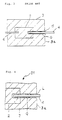
- Fig. 1 shows a tungsten halogen lamp.
- Molybdenum foils 2 are inserted in the sealed pinched base regions 3, which are formed at both ends of the lamp 10.
- a cap pin 4 To each of the outside edges of the molybdenum foils 2 is soldered a cap pin 4 as an outer lead which extends outward from the cap or end face 3a of the base region 3.
- a filament 5 In an envelope 1 is located a filament 5, whose two ends are connected by means of inner leads 6 to the inner edges of the molybdenum foils 2.
- Fig. 2 is a larger-scale view of one of the sealed base regions 3 of the lamp 10. From the outer end or face 3a of the sealed base region 3 to the outer edge or end of the molybdenum foil 2, a microscopically small cavity G extends around the cap pin 4. This cavity is formed, in any event, as a result of the different thermal expansion coefficients between the quartz glass from which the envelope 1 is made and the material of the cap pin 4. Therefore, it is not possible to prevent the formation of such cavity G.
- the cavity extends from the outer end 3a of the sealed base region 3 to the outer end of the molybdenum foil 2.
- Oxygen speeds up the oxidation of the molybdenum foil 2. This oxidation leads to premature cracking of the molybdenum foil 2, which shortens the life of the lamp 10.
- Such oxidation in particular becomes a problem, if the sealed base region temperature rises above 350 °C.
- Fig. 3 Illustrated in Fig. 3 is a hitherto adopted solution for eliminating the aforementioned deficiency.
- the cap pin 4 at the outer end 3a in the sealed base region 3 is smeared with a tacky, vitreous material 15.
- This tacky, material 15 is formed by glass powder having a low melting point.
- a solution is e.g. described in US-A- 4 522 925.
- US patent 4,835,439 describes an arrangement of a sealed base region, in which a solution of alkali metal silicate is injected into the cavity G in order to eliminate the aforementioned deficiency.
- the vitreous material melts, and then solidifies when switching the lamp off.
- the melting and resolidification of the vitreous material leads to the formation of numerous small cracks, which, when the lamp is switched off, allow the air to penetrate into the cavity G.
- the hitherto provided vitreous material has not been sufficiently effective for sealing the cavity G, and consequently, a long lamp life does not result therefrom. It is also difficult, due to the tackiness of the vitreous material 15, to automate the smearing process.
- the alkali metal silicate solution described in US patent 4,835,439 can be relatively easily injected into the cavity G, due to its good flow behavior. However, if the temperature rises above 350 °C, as stated, the oxidation prevention obtained is not adequate. Another disadvantage is that it takes a relatively long time for the filled solution to dry and harden.
- the present invention has been based on the aforementioned facts.
- the first object of the invention is to provide a lamp with a foil seal arrangement, which has in the sealed area an incorporated molybdenum foil, and which is characterized by a long life.
- a further object of the invention is to provide a simple method for the manufacture of an electric lamp with the novel foil seal arrangement.
- an electric lamp comprising a filament or an electrode and an envelope:
- the ends of the envelope are sealed with a foil seal arrangement.
- a molybdenum foil is incorporated into the sealed region and is connected to an outer lead.
- the surface of the molybdenum foil, in the sealed region is coated with lead oxide or with a sealing material whose main constituent is lead oxide.
- the sealed region will have a microscopically small cavity, which extends from the outer end face of the sealed region along the outer lead to the outer end or edge of the molybdenum foil.
- this object is achieved by the step of inserting a molybdenum foil in the sealed region of the envelope, connecting to an outer lead, and injecting a sealing solution, resulting from the dissolving of a sealing compound or composition into the microscopically small cavity extending along the outer lead up to the outer end of the molybdenum foil.
- the sealing compound is lead oxide or a material, whose main constituent is lead oxide, or a material from which lead oxide is produced by the thermal decomposition of the sealing material or compound.
- the electric lamp with the foil seal arrangement is characterized by a surface coating of the molybdenum foil, which is exposed to the cavity along the outer lead in the sealed region, and thus this surface coating essentially of lead oxide prevents oxidation of the molybdenum foil.
- the sealing solution used in the present invention can easily be introduced into the cavity extending along the outer lead, conductor, wire or terminal in the sealed region due to its high fluidity, i.e. low viscosity, which simplifies the manufacture of an electric lamp with a foil seal arrangement and results in ready attainment of the desired rating.
- FIG. 4 An example of the electric lamp according to the invention is shown in Fig. 4 and comprises a quartz glass envelope 21 with sealed regions 3.
- a molybdenum foil 2 to which is connected an outer lead 4.
- the surface of the molybdenum foil 2, which is exposed to a cavity G extending along the outer lead 4 is covered with lead oxide or a sealing material, whose main constituent is lead oxide.
- the above-described electric lamp with the novel foil seal arrangement is manufactured in the following way.
- a sealing solution By dissolving a preselected sealing compound in a suitable solvent, a sealing solution is obtained, which upon heating will thermally decompose to generate lead oxide or a sealing material whose main constituent is lead oxide.
- a small amount of the sealing solution L is injected into cavity G by means of a suitable syringe.
- the sealing solution enters cavity G at the outer face or end 3a along the outer lead 4. Due to its highly liquid nature, low viscosity, the sealing solution L flows extremely smoothly into the cavity G, which, without the aid of a special means or appliance, other than the syringe, will be completely filled with the sealing solution L.
- the sealed region 3 is heated to 500 °C for example, or such other appropriate temperature to decompose the sealing compound and produce a lead oxide coating of foil 2 and lead 4 by thermal decomposition of the sealing compound.
- the sealing material S whose main constituent is lead oxide covers the surface of the molybdenum foil 2 and lead 4 which are exposed in the cavity G, as shown in Fig. 5.
- Suitable examples of the sealing compound are lead nitrate and lead acetate. Due to the high solubility of these sealing compounds in water, the water can be used, and is preferred, as the solvent for the sealing solution. Other solvents for lead nitrate and lead acetate may also be used. If water is used as the solvent, the water can e.g. contain a little alcohol, which further improves the flow behavior of the sealing solution. If as the sealing solution L, use is made of an aqueous solution of lead nitrate or lead acetate, the desired concentration is ⁇ 0.2 mole/liter. With a concentration lower than 0.2 mole/l of the aqueous solution, the lead oxide covering is, in many cases, not thick enough to effectively prevent oxidation. The aqueous solution can also be saturated.
- Alkali metal salt or/and boric acid or/and a metaboric acid can also be added as an addition in the above-described sealing solution L when it is an aqueous solution of lead nitrate or lead acetate.
- This additional material easily dissolves in the aqueous lead nitrate or lead acetate solution without increasing the viscosity, so that the sealing solution L can be uniformly and easily introduced into the cavity G of the sealed region.
- the sealing material S formed of lead oxide, generated from the aqueous solution of the lead nitrate or lead acetate, contains as a residual trace the constituent alkali metal salt or boric acid or metaboric acid, so that the effect of covering the molybdenum foil exposed in the cavity G is increased.
- alkali metal salt water-soluble salt like nitrate, hydroxide, chloride or carbonate of alkali metal e.g. lithium, sodium or potassium, can be used.
- the desired ratio between the addition of the aforementioned additional material to the sealing solution in the present invention is 1 mole of lead (Pb) contained in the sealing solution to ⁇ 0.12 mole of alkali metal salt or ⁇ 0.02 mole of boric acid or metaboric acid. If the additional material proportion in the sealing solution is excessive, there is a risk of etching of the molybdenum foil.
- Dye can also be dissolved in the aforementioned inventive sealing solution.
- the sealing solution comprising the aqueous solution of lead nitrate or lead acetate
- a water-soluble dye e.g. amaranth (red), indigo carmine (blue), acid violet 6 B (violet) or rodamine B (light red).
- the sealing solution with a dye can be visually detected through the color, which makes it possible to easily identify visually the cavity filling level resulting from the injection of the aforementioned sealing solution and to inspect the integrity.
- the solution can easily be injected into the cavity with a syringe or introduced by a glass rod.
- the lamp to which the aforementioned embodiments refer is an incandescent lamp provided with an envelope having a sealed region at both ends.
- the present invention can also be used in the case of a lamp with a different construction, provided that it has a sealed region in which is incorporated a molybdenum foil.
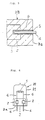
- the invention can be used in the case of a lamp 20, which comprises an envelope 21, which is provided at one end with a sealed region 3 in which are incorporated two or more molybdenum foils 2.
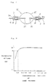
- the invention can also be used with a discharge lamp 30, which has a spherical envelope 31, which comprises two outer leads 4 connected to the opposite outer ends of the molybdenum foils 2 and a discharge electrode 25, as well as a discharge electrode 26.
- the filament is 5 and the inner lead is 6.
- sealing solutions 1 to 6 were prepared from the following materials in each case dissolved in water, and incorporating the red, water-soluble dye amaranth:
- Incandescent lamp types having one or more sealed regions each incorporating a molybdenum foil were assembled by conventional and known manufacturing steps.
- the aforementioned sealing solutions 1 to 6 were injected with a syringe around the outer lead in each sealed region. It was confirmed visually that the injected sealing solution flowed smoothly into the cavity and filled the entire cavity area. Subsequently, the aforementioned sealed regions containing the sealing solutions were dried and heated and the sealing materials thermally decomposed in a furnace at 500 °C. The water-soluble dye decomposed and the color of the sealing solutions disappeared.
- the lamps 1 to 6 of each type underwent a series of durability or life tests under different conditions.
- One-sided in this case means a lamp having a bulb, which is provided at one end with a sealed region in which are incorporated two molybdenum foils.
- Tewo-sided means a lamp having a bulb containing at both ends in each case one sealed region, in which is incorporated a molybdenum foil.
- Aqueous lead nitrate solutions were prepared with different concentrations. Each individual solution was used in the same way as in test A of example 1 for treating the sealed region of a lamp with a foil seal arrangement (lamp type DYS) for obstruction purposes. Tests were carried out under the operating condition I. The ratio to be determined by the aforementioned test between the lead nitrate concentration in the sealing solution used and the life of the lamp is shown by the course of the curve in Fig. 8. On the ordinate axis is plotted in percentage form the quotient of the projected desired life of the filament as the denominator and the lighting time as the numerator until the particular lamp could no longer be used due to foil cracking. 100% e.g.
- Fig. 8 shows that the weaker the lead nitrate concentration the earlier cracking occurs in the foil. As mentioned above, the reason for this is that in the case of a weak concentration the thickness of the lead oxide covering is thin and then not adequate to effectively prevent oxidation. It follows from Fig. 8 that a sufficiently long lamp life is obtained if the lead nitrate concentration in the sealing solution is ⁇ 0.2 mole/l.
- the exposed foil and lead are covered with lead oxide or with a sealing amterial whose main constituent is lead oxide.
- a sealing amterial whose main constituent is lead oxide.
- the present invention provides an electric lamp with a foil seal arrangement, which has a long life. Due to its low viscosity, the inventively used sealing solution easily penetrates into the cavity along the outer lead in the sealed region, which facilitates sealing solution injection and adequately supports the automation of the operation.
- the present invention provides a simple manufacturing method for an electric lamp with a foil seal arrangement, which has a long life.
Landscapes
- Vessels And Coating Films For Discharge Lamps (AREA)
- Manufacture Of Electron Tubes, Discharge Lamp Vessels, Lead-In Wires, And The Like (AREA)
Description
- The invention relates to an electric lamp with a hermetically closed sealing region incorporating a molybdenum foil and to a method for its manufacture.
- For the hermetic sealing of the quartz glass bulb of an incandescent lamp or a discharge lamp, it is generally known to use a metal foil seal.
- For example, Fig. 1 shows a tungsten halogen lamp. Molybdenum
foils 2 are inserted in the sealed pinchedbase regions 3, which are formed at both ends of thelamp 10. To each of the outside edges of themolybdenum foils 2 is soldered acap pin 4 as an outer lead which extends outward from the cap or end face 3a of thebase region 3. In anenvelope 1 is located afilament 5, whose two ends are connected by means ofinner leads 6 to the inner edges of themolybdenum foils 2. - Fig. 2 is a larger-scale view of one of the sealed
base regions 3 of thelamp 10. From the outer end or face 3a of the sealedbase region 3 to the outer edge or end of themolybdenum foil 2, a microscopically small cavity G extends around thecap pin 4. This cavity is formed, in any event, as a result of the different thermal expansion coefficients between the quartz glass from which theenvelope 1 is made and the material of thecap pin 4. Therefore, it is not possible to prevent the formation of such cavity G. - Air, including oxygen, passes into the aforementioned cavity G around the
cap pin 4. As noted, the cavity extends from the outer end 3a of the sealedbase region 3 to the outer end of themolybdenum foil 2. Oxygen speeds up the oxidation of themolybdenum foil 2. This oxidation leads to premature cracking of themolybdenum foil 2, which shortens the life of thelamp 10. Such oxidation in particular becomes a problem, if the sealed base region temperature rises above 350 °C. - Illustrated in Fig. 3 is a hitherto adopted solution for eliminating the aforementioned deficiency. The
cap pin 4 at the outer end 3a in the sealedbase region 3 is smeared with a tacky,vitreous material 15. This tacky,material 15 is formed by glass powder having a low melting point. Thevitreous material 15, which is subsequently melted by heating, seals the opening of the cavity G. Such a solution is e.g. described in US-A- 4 522 925. - US patent 4,835,439 describes an arrangement of a sealed base region, in which a solution of alkali metal silicate is injected into the cavity G in order to eliminate the aforementioned deficiency.
- In the previously described arrangement of the sealed base region, in which the opening of the cavity G is sealed with the low melting point
vitreous material 15, it would appear to be disadvantageous that when switching on the lamp, the vitreous material melts, and then solidifies when switching the lamp off. The melting and resolidification of the vitreous material leads to the formation of numerous small cracks, which, when the lamp is switched off, allow the air to penetrate into the cavity G. Thus, the hitherto provided vitreous material has not been sufficiently effective for sealing the cavity G, and consequently, a long lamp life does not result therefrom. It is also difficult, due to the tackiness of thevitreous material 15, to automate the smearing process. - The alkali metal silicate solution described in US patent 4,835,439 can be relatively easily injected into the cavity G, due to its good flow behavior. However, if the temperature rises above 350 °C, as stated, the oxidation prevention obtained is not adequate. Another disadvantage is that it takes a relatively long time for the filled solution to dry and harden.
- The present invention has been based on the aforementioned facts. The first object of the invention is to provide a lamp with a foil seal arrangement, which has in the sealed area an incorporated molybdenum foil, and which is characterized by a long life.
- A further object of the invention is to provide a simple method for the manufacture of an electric lamp with the novel foil seal arrangement.
- According to the invention this object is achieved by providing an electric lamp comprising a filament or an electrode and an envelope: The ends of the envelope are sealed with a foil seal arrangement. A molybdenum foil is incorporated into the sealed region and is connected to an outer lead. The surface of the molybdenum foil, in the sealed region, is coated with lead oxide or with a sealing material whose main constituent is lead oxide. As noted, the sealed region will have a microscopically small cavity, which extends from the outer end face of the sealed region along the outer lead to the outer end or edge of the molybdenum foil.
- With respect to the manufacturing method for the electric lamp with the foil seal arrangement, according to the invention this object is achieved by the step of inserting a molybdenum foil in the sealed region of the envelope, connecting to an outer lead, and injecting a sealing solution, resulting from the dissolving of a sealing compound or composition into the microscopically small cavity extending along the outer lead up to the outer end of the molybdenum foil. The sealing compound is lead oxide or a material, whose main constituent is lead oxide, or a material from which lead oxide is produced by the thermal decomposition of the sealing material or compound.
- The effect of the invention is that the electric lamp with the foil seal arrangement is characterized by a surface coating of the molybdenum foil, which is exposed to the cavity along the outer lead in the sealed region, and thus this surface coating essentially of lead oxide prevents oxidation of the molybdenum foil.
- The sealing solution used in the present invention can easily be introduced into the cavity extending along the outer lead, conductor, wire or terminal in the sealed region due to its high fluidity, i.e. low viscosity, which simplifies the manufacture of an electric lamp with a foil seal arrangement and results in ready attainment of the desired rating.
-
- Fig. 1
- Diagrammatically shows a view of an incandescent halogen lamp, according to the prior art.
- Fig. 2
- Diagrammatically shows on a larger scale, a cross-section through a sealed region of the incandescent halogen lamp according to Fig. 1.
- Fig. 3
- Diagrammatically shows a cross-section through a sealed region of an incandescent halogen lamp with a conventional seal according to the prior art.
- Fig. 4
- Diagrammatically shows on a larger scale a cross-sectional view of the sealed region on the end of an incandescent halogen lamp illustrating the manufacturing method according to the present invention.
- Fig. 5
- Diagrammatically shows on a larger scale a cross-sectional view of the covered foil and outer lead according to the present invention.
- Fig. 6
- Shows a diagrammatic view of another type of lamp incorporating the present invention.
- Fig. 7
- Diagrammatically shows a view of a discharge lamp using the present invention.
- Fig. 8
- Graphically shows the relationship between the lead nitrate concentration of a sealing solution and the life of an electric lamp with a foil seal arrangement having lead oxide derived from the lead nitrate sealing solution.
- The invention will now be specifically described with reference to preferred embodiments.
- An example of the electric lamp according to the invention is shown in Fig. 4 and comprises a
quartz glass envelope 21 with sealedregions 3. In each sealedregion 3 is incorporated amolybdenum foil 2 to which is connected anouter lead 4. The surface of themolybdenum foil 2, which is exposed to a cavity G extending along theouter lead 4 is covered with lead oxide or a sealing material, whose main constituent is lead oxide. The above-described electric lamp with the novel foil seal arrangement is manufactured in the following way. - By dissolving a preselected sealing compound in a suitable solvent, a sealing solution is obtained, which upon heating will thermally decompose to generate lead oxide or a sealing material whose main constituent is lead oxide. As shown in Fig. 4, a small amount of the sealing solution L is injected into cavity G by means of a suitable syringe. The sealing solution enters cavity G at the outer face or end 3a along the
outer lead 4. Due to its highly liquid nature, low viscosity, the sealing solution L flows extremely smoothly into the cavity G, which, without the aid of a special means or appliance, other than the syringe, will be completely filled with the sealing solution L. - After the sealing solution has been injected in this way into the cavity G of the sealed
region 3 and has dried, the sealedregion 3 is heated to 500 °C for example, or such other appropriate temperature to decompose the sealing compound and produce a lead oxide coating offoil 2 and lead 4 by thermal decomposition of the sealing compound. - The sealing material S, whose main constituent is lead oxide covers the surface of the
molybdenum foil 2 and lead 4 which are exposed in the cavity G, as shown in Fig. 5. - Suitable examples of the sealing compound are lead nitrate and lead acetate. Due to the high solubility of these sealing compounds in water, the water can be used, and is preferred, as the solvent for the sealing solution. Other solvents for lead nitrate and lead acetate may also be used. If water is used as the solvent, the water can e.g. contain a little alcohol, which further improves the flow behavior of the sealing solution. If as the sealing solution L, use is made of an aqueous solution of lead nitrate or lead acetate, the desired concentration is ≧ 0.2 mole/liter. With a concentration lower than 0.2 mole/l of the aqueous solution, the lead oxide covering is, in many cases, not thick enough to effectively prevent oxidation. The aqueous solution can also be saturated.
- Alkali metal salt or/and boric acid or/and a metaboric acid can also be added as an addition in the above-described sealing solution L when it is an aqueous solution of lead nitrate or lead acetate. This additional material easily dissolves in the aqueous lead nitrate or lead acetate solution without increasing the viscosity, so that the sealing solution L can be uniformly and easily introduced into the cavity G of the sealed region. The sealing material S formed of lead oxide, generated from the aqueous solution of the lead nitrate or lead acetate, contains as a residual trace the constituent alkali metal salt or boric acid or metaboric acid, so that the effect of covering the molybdenum foil exposed in the cavity G is increased.
- As a suitable alkali metal salt, water-soluble salt like nitrate, hydroxide, chloride or carbonate of alkali metal e.g. lithium, sodium or potassium, can be used. The desired ratio between the addition of the aforementioned additional material to the sealing solution in the present invention is 1 mole of lead (Pb) contained in the sealing solution to ≦ 0.12 mole of alkali metal salt or ≦ 0.02 mole of boric acid or metaboric acid. If the additional material proportion in the sealing solution is excessive, there is a risk of etching of the molybdenum foil.
- Dye can also be dissolved in the aforementioned inventive sealing solution. In the sealing solution, comprising the aqueous solution of lead nitrate or lead acetate, one can use a water-soluble dye, e.g. amaranth (red), indigo carmine (blue), acid violet 6 B (violet) or rodamine B (light red). The sealing solution with a dye can be visually detected through the color, which makes it possible to easily identify visually the cavity filling level resulting from the injection of the aforementioned sealing solution and to inspect the integrity.
- Due to the highly fluid nature of the aforementioned sealing solution, the solution can easily be injected into the cavity with a syringe or introduced by a glass rod.
- The lamp to which the aforementioned embodiments refer is an incandescent lamp provided with an envelope having a sealed region at both ends. However, the present invention can also be used in the case of a lamp with a different construction, provided that it has a sealed region in which is incorporated a molybdenum foil. As shown in Fig. 6, the invention can be used in the case of a lamp 20, which comprises an
envelope 21, which is provided at one end with a sealedregion 3 in which are incorporated two or more molybdenum foils 2. However, as shown in Fig. 7, the invention can also be used with adischarge lamp 30, which has aspherical envelope 31, which comprises twoouter leads 4 connected to the opposite outer ends of the molybdenum foils 2 and adischarge electrode 25, as well as a discharge electrode 26. In Fig. 6, the filament is 5 and the inner lead is 6. - Embodiments of the invention are further illustrated hereinafter.
- The following
sealing solutions 1 to 6 were prepared from the following materials in each case dissolved in water, and incorporating the red, water-soluble dye amaranth:
- Incandescent lamp types having one or more sealed regions each incorporating a molybdenum foil were assembled by conventional and known manufacturing steps. The
aforementioned sealing solutions 1 to 6 were injected with a syringe around the outer lead in each sealed region. It was confirmed visually that the injected sealing solution flowed smoothly into the cavity and filled the entire cavity area. Subsequently, the aforementioned sealed regions containing the sealing solutions were dried and heated and the sealing materials thermally decomposed in a furnace at 500 °C. The water-soluble dye decomposed and the color of the sealing solutions disappeared. - The
lamps 1 to 6 of each type (cf. table 1) treated in the aforementioned manner with thesealing solutions 1 to 6 underwent a series of durability or life tests under different conditions. For comparison purposes use was also made of lamps, in which the openings of the cavity in the sealed region were not obstructed (filled), lamps using as the sealing compound low melting point glass; and lamps in which the sealing compound was constituted by an aqueous potassium silicate solution. All lamps underwent the same tests. - The details of the lamp types used for the burning period tests and the conditions under which lighting took place are as follows:
-
- DYS:
- a lamp of the same construction as Ushio ordering code JCD 120 V/600 WC, one-sided cap, circular bulb and rated consumption 600 W.
- DXW:
- a lamp of the same construction as Ushio ordering code JPD 230 V/1000 WC₅, two-sided cap, rod-like tubular bulb and rated
consumption 1 kW. - FCR:
- a lamp of the same construction as Ushio ordering code JC 12 V-100 W. One-sided cap, rod-like tubular bulb and rated consumption 100 W.
- H3:
- a lamp of the same construction as Ushio ordering code JA 12 V-55 W, particularly developed for cars, one-sided cap, rod-like tubular bulb and rated consumption 55 W.
- "One-sided" in this case means a lamp having a bulb, which is provided at one end with a sealed region in which are incorporated two molybdenum foils. "Two-sided" means a lamp having a bulb containing at both ends in each case one sealed region, in which is incorporated a molybdenum foil.
-
- I. Lamp operated for one hour, then switched off, followed by a 30 minute pause. This process is repeated in a lamp house.
- II. Uninterrupted testing at 600 °C in an electric furnace.
- III. Uninterrupted testing at 500 °C in an electric furnace.
- The results are given in table 1 on the last page of this detailed description.
- The figures in the table mean the time up to which the foil cracked due to oxidation. "180 or more", "220 or more" and "440 or more" mean that the molybdenum foil of the particular lamp did not suffer cracking by oxidation after an illuminated period of 180, 220 and 440 hours, respectively, but the lamp was unusable for some other reason. It follows from table 1 that under illumination conditions I, II and III the invention is superior to the prior art, with conditions II and III revealing a marked superiority.
- Aqueous lead nitrate solutions were prepared with different concentrations. Each individual solution was used in the same way as in test A of example 1 for treating the sealed region of a lamp with a foil seal arrangement (lamp type DYS) for obstruction purposes. Tests were carried out under the operating condition I. The ratio to be determined by the aforementioned test between the lead nitrate concentration in the sealing solution used and the life of the lamp is shown by the course of the curve in Fig. 8. On the ordinate axis is plotted in percentage form the quotient of the projected desired life of the filament as the denominator and the lighting time as the numerator until the particular lamp could no longer be used due to foil cracking. 100% e.g. means that during the illuminations the foil did not crack by the time the desired filament life was reached. 50% e.g. means that during the illumination cracking occurred on the foil after only half the desired filament life was reached. Fig. 8 shows that the weaker the lead nitrate concentration the earlier cracking occurs in the foil. As mentioned above, the reason for this is that in the case of a weak concentration the thickness of the lead oxide covering is thin and then not adequate to effectively prevent oxidation. It follows from Fig. 8 that a sufficiently long lamp life is obtained if the lead nitrate concentration in the sealing solution is ≧ 0.2 mole/l.
- In the present invention, the exposed foil and lead are covered with lead oxide or with a sealing amterial whose main constituent is lead oxide. This increases the corrosion resistance of the molybdenum foil, and consequently, adequately prevents the foil from oxidation by oxygen in the air. Thus, the present invention provides an electric lamp with a foil seal arrangement, which has a long life. Due to its low viscosity, the inventively used sealing solution easily penetrates into the cavity along the outer lead in the sealed region, which facilitates sealing solution injection and adequately supports the automation of the operation. Thus, the present invention provides a simple manufacturing method for an electric lamp with a foil seal arrangement, which has a long life.

Claims (7)
- Electric lamp (20) having an envelope (21), a filament (5) supported in the envelope (21), sealing means sealing said envelope (21) and incorporating a molybdenum foil (2) attached to said filament (5), an outer lead (4) connected to the foil (2) and projecting out of said sealing means, a microscopically small cavity (G) extending from the outer end (3a) of the sealing region along the outer lead (4) up to the outer end of the molybdenum foil (2), characterized in that a sealing material (S) is composed of lead oxide covering said outer end of the molybdenum foil (2).
- Manufacturing method for an electric lamp (20; 30) having an envelope (21; 31) with a foil seal arrangement incorporating a molybdenum foil (2) and to which is connected an outer lead (4) and which is characterized by a microscopically small cavity (G) surrounding the outer lead (4) and the area of connection between the outer lead (4) and foil (2), characterized in the steps of injecting a sealing solution (L) containing a sealing compound from which lead oxide can be obtained by thermal decomposition into the microscopically small cavity (G), and thermally decomposing the sealing compound to coat lead oxide on the outer end of the molybdenum foil (2).
- Manufacturing method according to claim 2, wherein the sealing solution (L) is an aqueous solution of lead nitrate or lead acetate, with a concentration ≧ 0.2 mole/l.
- Manufacturing method according to claim 3, wherein the sealing solution (L) contains alkali metal salt, in a molar ratio ≦ 12% to the lead content of the solution.
- Manufacturing method according to claim 3 or 4, wherein the sealing solution (L) contains boric or metaboric acid, in a molar ratio of ≦ 2% to the lead content of the solution.
- Manufacturing method according to one of the claims 3 to 5, wherein the sealing solution (L) contains a dye.
- Electric lamp (30) having an envelope (31), at least one electrode (25, 26) supported in the envelope (31), sealing means sealing said envelope (31) and incorporating a molybdenum foil (2) attached to said electrode (25, 26), an outer lead (4) connected to the foil (2) and projecting out of said sealing means, a microscopically small cavity (G) extending from the outer end (3a) of the sealing region along the outer lead (4) up to the outer end of the molybdenum foil (2), characterized in that a sealing material (S) is composed of lead oxide covering said outer end of the molybdenum foil (2).
Applications Claiming Priority (2)
| Application Number | Priority Date | Filing Date | Title |
|---|---|---|---|
| JP2412943A JPH0654657B2 (en) | 1990-12-25 | 1990-12-25 | Foil seal lamp and manufacturing method thereof |
| JP412943/90 | 1990-12-25 |
Publications (3)
| Publication Number | Publication Date |
|---|---|
| EP0492189A2 EP0492189A2 (en) | 1992-07-01 |
| EP0492189A3 EP0492189A3 (en) | 1992-12-02 |
| EP0492189B1 true EP0492189B1 (en) | 1995-02-22 |
Family
ID=18521683
Family Applications (1)
| Application Number | Title | Priority Date | Filing Date |
|---|---|---|---|
| EP91120779A Expired - Lifetime EP0492189B1 (en) | 1990-12-25 | 1991-12-03 | Electric lamp with foil seal construction and method for its manufacture |
Country Status (5)
| Country | Link |
|---|---|
| US (1) | US5310374A (en) |
| EP (1) | EP0492189B1 (en) |
| JP (1) | JPH0654657B2 (en) |
| KR (1) | KR940011727B1 (en) |
| DE (1) | DE69107595T2 (en) |
Families Citing this family (17)
| Publication number | Priority date | Publication date | Assignee | Title |
|---|---|---|---|---|
| KR100382059B1 (en) * | 1995-12-18 | 2003-07-18 | 삼성에스디아이 주식회사 | Metal halide lamp manufacturing method |
| US5877590A (en) * | 1996-07-12 | 1999-03-02 | Koito Manufacturing Co., Ltd. | Discharge lamp arc tube and method of producing the same |
| JP3424516B2 (en) | 1997-07-30 | 2003-07-07 | 松下電器産業株式会社 | Halogen bulb and method of manufacturing the same |
| JP4388699B2 (en) * | 1998-08-13 | 2009-12-24 | コーニンクレッカ フィリップス エレクトロニクス エヌ ヴィ | Electric lamp with coated outer current conductor |
| DE19961551A1 (en) * | 1999-12-20 | 2001-06-21 | Patent Treuhand Ges Fuer Elektrische Gluehlampen Mbh | Melting film and associated lamp with this film |
| JP3908520B2 (en) * | 2001-11-29 | 2007-04-25 | 富士通株式会社 | Semiconductor integrated circuit and test method for semiconductor integrated circuit |
| JP4200823B2 (en) * | 2002-08-22 | 2008-12-24 | ウシオ電機株式会社 | Foil seal lamp |
| US7153179B2 (en) * | 2002-11-07 | 2006-12-26 | Advanced Lighting Technologies, Inc. | Oxidation-protected metallic foil and method |
| US8277274B2 (en) * | 2002-11-07 | 2012-10-02 | Advanced Lighting Technologies, Inc. | Apparatus and methods for use of refractory abhesives in protection of metallic foils and leads |
| WO2004090935A2 (en) * | 2003-04-10 | 2004-10-21 | Koninklijke Philips Electronics N.V. | Lamp assembly |
| JP4055633B2 (en) * | 2003-04-14 | 2008-03-05 | ウシオ電機株式会社 | Foil seal lamp |
| WO2004097892A2 (en) * | 2003-05-01 | 2004-11-11 | Koninklijke Philips Electronics N.V. | Method of manufacturing a lamp having an oxidation-protected lead wire |
| US7759871B2 (en) * | 2005-12-16 | 2010-07-20 | General Electric Company | High temperature seal for electric lamp |
| WO2008145173A1 (en) * | 2007-05-25 | 2008-12-04 | Osram Gesellschaft mit beschränkter Haftung | Electric lamp with a light bulb and method for the production of an electric lamp |
| US20090039785A1 (en) * | 2007-08-08 | 2009-02-12 | Ushio Denki Kabushiki Kaisha | Discharge lamp |
| JP4539705B2 (en) * | 2007-10-22 | 2010-09-08 | ウシオ電機株式会社 | Foil seal lamp and method for manufacturing foil seal lamp |
| JP5338557B2 (en) * | 2009-08-19 | 2013-11-13 | ウシオ電機株式会社 | Lamp with base |
Family Cites Families (6)
| Publication number | Priority date | Publication date | Assignee | Title |
|---|---|---|---|---|
| FR1317782A (en) * | 1961-03-16 | 1963-05-08 | ||
| US3973975A (en) * | 1972-04-21 | 1976-08-10 | Owens-Illinois, Inc. | PbO-containing sealing glass with higher oxide of a cation to avoid PbO reduction |
| GB2120006B (en) * | 1982-05-07 | 1985-10-09 | Gen Electric Plc | Diversion of heat and light from ribbon seals in high-power electric lamps |
| US4522925A (en) * | 1983-09-01 | 1985-06-11 | Owens-Illinois, Inc. | Sealing glass and method of making a Willemite filler therefor |
| DE3615944A1 (en) * | 1986-05-12 | 1987-11-19 | Patent Treuhand Ges Fuer Elektrische Gluehlampen Mbh | ELECTRIC LAMP |
| US4835439A (en) * | 1987-09-29 | 1989-05-30 | General Electric Company | Increasing the oxidation resistance of molybdenum and its use for lamp seals |
-
1990
- 1990-12-25 JP JP2412943A patent/JPH0654657B2/en not_active Expired - Lifetime
-
1991
- 1991-08-19 KR KR1019910014280A patent/KR940011727B1/en not_active Expired - Fee Related
- 1991-12-03 EP EP91120779A patent/EP0492189B1/en not_active Expired - Lifetime
- 1991-12-03 DE DE69107595T patent/DE69107595T2/en not_active Expired - Lifetime
-
1993
- 1993-08-25 US US08/111,761 patent/US5310374A/en not_active Expired - Lifetime
Also Published As
| Publication number | Publication date |
|---|---|
| KR940011727B1 (en) | 1994-12-23 |
| EP0492189A3 (en) | 1992-12-02 |
| KR920013587A (en) | 1992-07-29 |
| JPH04272645A (en) | 1992-09-29 |
| DE69107595D1 (en) | 1995-03-30 |
| EP0492189A2 (en) | 1992-07-01 |
| DE69107595T2 (en) | 1995-07-20 |
| JPH0654657B2 (en) | 1994-07-20 |
| US5310374A (en) | 1994-05-10 |
Similar Documents
| Publication | Publication Date | Title |
|---|---|---|
| US5310374A (en) | Electric lamp with foil seal construction and method of producing the same | |
| US4835439A (en) | Increasing the oxidation resistance of molybdenum and its use for lamp seals | |
| US4766346A (en) | Lamp with low-toxicity, molybdenum-compatible sealing glass | |
| DE2512436A1 (en) | ELECTRIC DISCHARGE LAMP WITH A BOTTOM IN CHEMICAL POLISHED POLYCRYSTALLINE ALUMINUM OXYDE | |
| KR20030019167A (en) | High pressure discharge lamp and method for producing the same | |
| HU199195B (en) | Electric lamp with improved current lead-in | |
| US4199704A (en) | Alumina, calcia, baria, strontia sealing composition and article of manufacture | |
| US7019462B2 (en) | Sealing agent for a foil sealed lamp | |
| CN100481310C (en) | Metal foil seal lamp | |
| CN1269910A (en) | Long-life halogen cycle incandescent lamp and glass envelope composition | |
| US3721852A (en) | Refractory metal phosphate and phosphide coatings for refractory metal leads | |
| US4918353A (en) | Reflector and lamp combination | |
| US3785019A (en) | Process for producing lamps | |
| US3798058A (en) | Refractory metal phosphate and phosphide coatings for refractory metal leads and process for producing metal phosphides | |
| US3723792A (en) | Electric incandescent lamps having refractory metal phosphate and phosphide coatings for refractory metal leads | |
| EP0662704A1 (en) | Lamp and lighting apparatus utilizing same | |
| US6674001B2 (en) | Solder glass and electrical device employing same | |
| CA1227223A (en) | Solder glass and electrical device employing same | |
| JP3075506B2 (en) | Low melting point glass and lamp seal using the same | |
| RU2436741C9 (en) | Method to produce glassy composition and container for its thermal treatment | |
| US3919578A (en) | Tungsten-halogen cycle electric incandescent lamp and method of manufacturing | |
| JP2782609B2 (en) | How to make a light bulb | |
| US20060273728A1 (en) | High-pressure gas discharge lamp | |
| KR200357222Y1 (en) | Cold Cathode Fluorescent Lamp | |
| CN100351194C (en) | Long life halogen cycle incandescent lamp and glass envelope composition |
Legal Events
| Date | Code | Title | Description |
|---|---|---|---|
| PUAI | Public reference made under article 153(3) epc to a published international application that has entered the european phase |
Free format text: ORIGINAL CODE: 0009012 |
|
| AK | Designated contracting states |
Kind code of ref document: A2 Designated state(s): DE GB NL |
|
| PUAL | Search report despatched |
Free format text: ORIGINAL CODE: 0009013 |
|
| AK | Designated contracting states |
Kind code of ref document: A3 Designated state(s): DE GB NL |
|
| 17P | Request for examination filed |
Effective date: 19930108 |
|
| 17Q | First examination report despatched |
Effective date: 19940725 |
|
| GRAA | (expected) grant |
Free format text: ORIGINAL CODE: 0009210 |
|
| AK | Designated contracting states |
Kind code of ref document: B1 Designated state(s): DE GB NL |
|
| REF | Corresponds to: |
Ref document number: 69107595 Country of ref document: DE Date of ref document: 19950330 |
|
| PLBE | No opposition filed within time limit |
Free format text: ORIGINAL CODE: 0009261 |
|
| STAA | Information on the status of an ep patent application or granted ep patent |
Free format text: STATUS: NO OPPOSITION FILED WITHIN TIME LIMIT |
|
| 26N | No opposition filed | ||
| REG | Reference to a national code |
Ref country code: GB Ref legal event code: IF02 |
|
| PGFP | Annual fee paid to national office [announced via postgrant information from national office to epo] |
Ref country code: NL Payment date: 20101220 Year of fee payment: 20 Ref country code: GB Payment date: 20101201 Year of fee payment: 20 |
|
| PGFP | Annual fee paid to national office [announced via postgrant information from national office to epo] |
Ref country code: DE Payment date: 20101130 Year of fee payment: 20 |
|
| REG | Reference to a national code |
Ref country code: DE Ref legal event code: R071 Ref document number: 69107595 Country of ref document: DE |
|
| REG | Reference to a national code |
Ref country code: DE Ref legal event code: R071 Ref document number: 69107595 Country of ref document: DE |
|
| REG | Reference to a national code |
Ref country code: NL Ref legal event code: V4 Effective date: 20111203 |
|
| REG | Reference to a national code |
Ref country code: GB Ref legal event code: PE20 Expiry date: 20111202 |
|
| PG25 | Lapsed in a contracting state [announced via postgrant information from national office to epo] |
Ref country code: NL Free format text: LAPSE BECAUSE OF EXPIRATION OF PROTECTION Effective date: 20111203 |
|
| PG25 | Lapsed in a contracting state [announced via postgrant information from national office to epo] |
Ref country code: GB Free format text: LAPSE BECAUSE OF EXPIRATION OF PROTECTION Effective date: 20111202 |
|
| PG25 | Lapsed in a contracting state [announced via postgrant information from national office to epo] |
Ref country code: DE Free format text: LAPSE BECAUSE OF EXPIRATION OF PROTECTION Effective date: 20111204 |