EP0491788B1 - A flywheel magneto arrangement - Google Patents
A flywheel magneto arrangement Download PDFInfo
- Publication number
- EP0491788B1 EP0491788B1 EP90913742A EP90913742A EP0491788B1 EP 0491788 B1 EP0491788 B1 EP 0491788B1 EP 90913742 A EP90913742 A EP 90913742A EP 90913742 A EP90913742 A EP 90913742A EP 0491788 B1 EP0491788 B1 EP 0491788B1
- Authority
- EP
- European Patent Office
- Prior art keywords
- core
- windings
- flywheel
- magneto
- groups
- Prior art date
- Legal status (The legal status is an assumption and is not a legal conclusion. Google has not performed a legal analysis and makes no representation as to the accuracy of the status listed.)
- Expired - Lifetime
Links
- 238000004804 winding Methods 0.000 claims abstract description 33
- 239000011295 pitch Substances 0.000 claims abstract description 21
- 238000002485 combustion reaction Methods 0.000 claims abstract description 7
- 238000010079 rubber tapping Methods 0.000 claims description 24
- 239000003990 capacitor Substances 0.000 claims description 2
- 230000005540 biological transmission Effects 0.000 claims 1
- 230000002401 inhibitory effect Effects 0.000 claims 1
- 239000004020 conductor Substances 0.000 abstract 1
- 230000006698 induction Effects 0.000 description 8
- 230000004907 flux Effects 0.000 description 7
- 238000000034 method Methods 0.000 description 6
- 230000000694 effects Effects 0.000 description 3
- 230000001419 dependent effect Effects 0.000 description 1
- 238000010586 diagram Methods 0.000 description 1
- 238000006073 displacement reaction Methods 0.000 description 1
- 230000001939 inductive effect Effects 0.000 description 1
Images




Classifications
-
- F—MECHANICAL ENGINEERING; LIGHTING; HEATING; WEAPONS; BLASTING
- F02—COMBUSTION ENGINES; HOT-GAS OR COMBUSTION-PRODUCT ENGINE PLANTS
- F02P—IGNITION, OTHER THAN COMPRESSION IGNITION, FOR INTERNAL-COMBUSTION ENGINES; TESTING OF IGNITION TIMING IN COMPRESSION-IGNITION ENGINES
- F02P1/00—Installations having electric ignition energy generated by magneto- or dynamo- electric generators without subsequent storage
- F02P1/02—Installations having electric ignition energy generated by magneto- or dynamo- electric generators without subsequent storage the generator rotor being characterised by forming part of the engine flywheel
-
- F—MECHANICAL ENGINEERING; LIGHTING; HEATING; WEAPONS; BLASTING
- F02—COMBUSTION ENGINES; HOT-GAS OR COMBUSTION-PRODUCT ENGINE PLANTS
- F02B—INTERNAL-COMBUSTION PISTON ENGINES; COMBUSTION ENGINES IN GENERAL
- F02B75/00—Other engines
- F02B75/02—Engines characterised by their cycles, e.g. six-stroke
- F02B2075/022—Engines characterised by their cycles, e.g. six-stroke having less than six strokes per cycle
- F02B2075/027—Engines characterised by their cycles, e.g. six-stroke having less than six strokes per cycle four
Definitions
- the invention relates to a flywheel magneto arrangement according to the first part of claim 1.
- the present invention relates to a solution of the problem mentioned above.
- the invention is based on a process of generating a trigger releasing pulse by using asymmetric magnetic field induction.
- the invention thus relates to an arrangement in fly-wheel magnetos for multiple cylinder combustion engines, said arrangement including a magnet core, which is divided into several like parts and carries windings, and magnet poles moveable in relation to the magnet core.
- the novelty of the invention resides essentially according to claim 1 in the feature that the number of core parts or divisions forms an integer and that half the number of parts forms an odd number.
- the magnet poles are arranged in groups with their polarity alternating, the pole pitch within the groups coinciding with the core pitch. Adjacent core parts, thus spaced one pitch, carry each its control windning connected to a circuit for sensing voltage polarity in order to produce distributed trigger signals for the respective engine cylinder.
- Fig. 1 shows diagrammatically the structure of a generator part of an arrangement according to the invention.
- Fig. 2 shows a circuit diagram for the ignition circuits of the cylinders in an associated combustion engine.
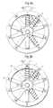
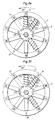
- Fig. 3 is divided into ten subfigures a-j which illustrate diagrammatically various conditions of induction during one revolution of the magneto flywheel.
- the generator part shown in Fig. 1 of the flywheel magneto comprises a flywheel 1 with eight permanent magnets forming poles 2-9 having different polarities indicated by N and S, that is, north and south. Said poles are so distributed that they are able to cooperate symmetrically with a core 10 having radially extending core legs 11-20. As can be seen the spacing or pitching is such that the number of core legs forms an even number, in this case ten, which divided into halves givs five, i.e. an odd number. As shown in the figure the magnet poles 2, 3, 4 and 5 form a group, in the illustrated case cooperating with the core legs 12, 13, 14 and 15. Poles 6, 7, 8 and 9 form a second group cooperating with core legs 17, 18, 19 and 20. Hence, with respect to spacing there is a gap between poles 2 and 9 and between poles 5 and 6.
- the core leg 11 carries a trigger winding 21 and the core leg 12 carries a trigger winding 22, the windings being connected such in the present case that they are in opposition with respect to induction.
- the trigger winding 21 has a tapping point 23 and the trigger winding 22 has a tapping point 24. Between the two windings there is a tapping point 25.
- a generator winding 26 for generating a charging voltage for the associated capacitor ignition system.
- winding 26 can be interconnected with other windings on legs 13-20 for generating the necessary voltage, but this is of secondary importance when it comes to explaining the present invention.
- Said last mentioned winding 26 has two tapping points 27 and 28.
- the flywheel is assumed to rotate about a central axis 29 in a direction of rotation indicated by the arrow 30.
- an indication 31 of rotation has been made on flywheel 1, said indication being located opposite the core leg 16 in Fig. 1.
- Fig. 2 the tapping points 23, 24 and 25 of windings 21 and 22 are shown connectable, as indicated by associated arrows 32, to inputs 33, 34 and 35 of a discriminator circuit 36.
- Said circuit has two outputs 37, 38 for control pulses to the respective trigger input of two ignition circuits 39, 40.
- a sparkplug 41, 42 is connected to the high voltage end of the respective ignition circuit.
- Fig. 3a the flywheel 1 assumes the same position as in Fig. 1. This means, considering the area about windings 21 and 22, that a magnetic flux path is established from pole 2, through leg 12, over to and through leg 13 to the south pole 3. This means in turn that when the said position is reached during rotation in the arrow 30 direction, it is assumed that a positive voltage half-wave is induced in winding 22, so that tapping point 24 shows a positive polarity in relation to tapping point 25. If the magneto flywheel is now rotated one pole pitch in the arrow 30 direction, i.e. so that indication 31 will arrive opposite core leg 20, see Fig. 3b, a magnetic flux path is created in the core legs 11 and 12 to the effect that voltages are induced in the related windings 21 and 22.
- pole 5 will arrive opposite the core leg 11, which means that a flux path including pole 4 will be created through legs 11 and 20. This means in turn that a negative voltage half-wave will be induced at tapping point 23 whereas winding 22 becomes dead, as no magnet pole cooperates with leg 12. This rotational position is an important position as will be disclosed in greater detail below.
- magnets 8 and 9 cause induction of a voltage in winding 21 such that a positive polarity appears on tapping point 23. Winding 22 will then be dead, as there is no pole opposite core leg 12. It is to be noted that indication 31 is now at a point which is displaced 180° in relationship to the point previously mentioned, see Fig. 3e viz., when the indication was opposite core leg 17. In the first mentioned position a positive half-wave was generated in winding 21, whereas a negative half-wave is created in the position now defined.
- tapping point 23 in relation to tapping point 25
- this voltage is fed to the discriminator circuit 36 on its inputs 33 and 35, respectively.
- a positive voltage wave appears on tapping point 23.
- magnet poles coact with the two core legs 11 and 12 the same voltage polarities appear on tapping points 23 and 24.
- circuit 36 has to be such that when tapping point 24 exhibits the same voltage as point 23 the circuit 36 will not react. If, however, there is no voltage on tapping point 24 the voltage induced in 21 has to be utilized by the circuit. On the other hand, if the circuit is such that when a positive induction appears on tapping point 23, i.e. as in the position latest described, the pulse is conducted to output 37 in order to initiate the ignition circuit 39 to ignite its sparkplug 41. When, however, the situation according to Fig. 3j occurs, a negative voltage appears on on tapping point 23 whereas tapping point 24 is dead.
- a negative pulse at input 33 means to the discriminator circuit 36 that a control pulse emerges on line 38, to the effect that the second cylinder ignition circuit 40 comes into action and a spark is tripped on its sparkplug 42.
- the arrangement disclosed makes it possible to attain a highly precise distribution of the ignition processes of two different cylinders.
- more cylinders than two can be supplied in the manner under consideration with pulses for controlling ignition processes, and the arrangement is useful to two-stroke as well as four-stroke engines.
- the essential point is that the number of core pitches or divisions has to be even, but half this number has always to be an odd number. Thus in the present case it is the question of ten core pitches, the half thus being five, i.e. an odd number, as stated. If the number of pitches is fourteen, half the number will be seven, and if the number of pitches is eighteen half the number will be nine etc.
- Such embodiments may of course be conceived wherein a plurality of gaps occur between the poles, that is, symmetrically not merely between poles 2 and 9 & 5 and 6 but also between other poles in structures having several, i.e. closely pitched core legs.
- the discriminator circuit 36 could, for example, be a micro computor, should such a solution be found appropriate.
Landscapes
- Engineering & Computer Science (AREA)
- Chemical & Material Sciences (AREA)
- Combustion & Propulsion (AREA)
- Mechanical Engineering (AREA)
- General Engineering & Computer Science (AREA)
- Ignition Installations For Internal Combustion Engines (AREA)
- Electronic Switches (AREA)
- Magnetic Bearings And Hydrostatic Bearings (AREA)
- Magnetic Resonance Imaging Apparatus (AREA)
Abstract
Description
- The invention relates to a flywheel magneto arrangement according to the first part of
claim 1. - In multiple cylinder combustion engines it is common practice to use, for distributing sparks to the various sparkplugs, a so called distributor, i.e. an arm synchronously coupled to the engine and having a contact function. In e.g. small two cylinder engines it could be structurally complicated as well as expensive to provide, in association with the flywheel magneto often used in such types of engines, also a distributor. There are possibilities nowadays to conduct the igniting processes by means of electronic control circuits so that igniting occurs at the proper time in the proper cylinder. However, also such solutions are comparatively expensive.
- The present invention relates to a solution of the problem mentioned above. The invention is based on a process of generating a trigger releasing pulse by using asymmetric magnetic field induction. The invention thus relates to an arrangement in fly-wheel magnetos for multiple cylinder combustion engines, said arrangement including a magnet core, which is divided into several like parts and carries windings, and magnet poles moveable in relation to the magnet core. The novelty of the invention resides essentially according to
claim 1 in the feature that the number of core parts or divisions forms an integer and that half the number of parts forms an odd number. Moreover, the magnet poles are arranged in groups with their polarity alternating, the pole pitch within the groups coinciding with the core pitch. Adjacent core parts, thus spaced one pitch, carry each its control windning connected to a circuit for sensing voltage polarity in order to produce distributed trigger signals for the respective engine cylinder. - The features characterizing the features of particular embodiments of the invention will appear from the accompanying dependent claims.
- The invention will be described in greater detail with reference to the accompanying drawings which illustrate embodiments of the invention.
- Fig. 1 shows diagrammatically the structure of a generator part of an arrangement according to the invention.
- Fig. 2 shows a circuit diagram for the ignition circuits of the cylinders in an associated combustion engine.
- Fig. 3 is divided into ten subfigures a-j which illustrate diagrammatically various conditions of induction during one revolution of the magneto flywheel.
- The generator part shown in Fig. 1 of the flywheel magneto comprises a
flywheel 1 with eight permanent magnets forming poles 2-9 having different polarities indicated by N and S, that is, north and south. Said poles are so distributed that they are able to cooperate symmetrically with acore 10 having radially extending core legs 11-20. As can be seen the spacing or pitching is such that the number of core legs forms an even number, in this case ten, which divided into halves givs five, i.e. an odd number. As shown in the figure themagnet poles core legs Poles core legs poles poles - The
core leg 11 carries a trigger winding 21 and thecore leg 12 carries a trigger winding 22, the windings being connected such in the present case that they are in opposition with respect to induction. The trigger winding 21 has atapping point 23 and the trigger winding 22 has atapping point 24. Between the two windings there is atapping point 25. As indicated by dashed lines there is on core leg 15 a generator winding 26 for generating a charging voltage for the associated capacitor ignition system. As a matter of course winding 26 can be interconnected with other windings on legs 13-20 for generating the necessary voltage, but this is of secondary importance when it comes to explaining the present invention. Said last mentioned winding 26 has twotapping points - The flywheel is assumed to rotate about a
central axis 29 in a direction of rotation indicated by thearrow 30. In order to explain in the following the various processes of induction, in particular in connection with Fig. 3, anindication 31 of rotation has been made onflywheel 1, said indication being located opposite thecore leg 16 in Fig. 1. - In Fig. 2 the
tapping points windings arrows 32, toinputs discriminator circuit 36. Said circuit has twooutputs ignition circuits sparkplug - In Fig. 3a the
flywheel 1 assumes the same position as in Fig. 1. This means, considering the area aboutwindings pole 2, throughleg 12, over to and throughleg 13 to thesouth pole 3. This means in turn that when the said position is reached during rotation in thearrow 30 direction, it is assumed that a positive voltage half-wave is induced in winding 22, so thattapping point 24 shows a positive polarity in relation totapping point 25. If the magneto flywheel is now rotated one pole pitch in thearrow 30 direction, i.e. so thatindication 31 will arrive oppositecore leg 20, see Fig. 3b, a magnetic flux path is created in thecore legs related windings tapping points indication 31 lands oppositecore leg 19, see Fig. 3c, also here a flux path arises, throughlegs tapping points flywheel 1 is rotated a further pole pitch, see Fig. 3d, i.e. so thatindication 31 will lie oppositecore leg 18,magnet poles legs tapping points pole 5 will arrive opposite thecore leg 11, which means that a fluxpath including pole 4 will be created throughlegs tapping point 23 whereas winding 22 becomes dead, as no magnet pole cooperates withleg 12. This rotational position is an important position as will be disclosed in greater detail below. - If the magneto flywheel is rotated one pole pitch further, see Fig. 3f,
indication 31 will land oppositecore leg 16, in doing whichpole 6 will be located oppositecore leg 12 andpole 7opposite core leg 13. Consequently a magnetic flux will arise in these core legs, said flux inducing a negative voltage attapping point 24. Rotating now one further pole pitch, see Fig. 3g, as in previous equivalent cases a flux will arise simultaneously throughlegs tapping points indication 31 isopposite core leg 12, see Fig. 3j,magnets tapping point 23. Winding 22 will then be dead, as there is no pole oppositecore leg 12. It is to be noted thatindication 31 is now at a point which is displaced 180° in relationship to the point previously mentioned, see Fig. 3e viz., when the indication was oppositecore leg 17. In the first mentioned position a positive half-wave was generated in winding 21, whereas a negative half-wave is created in the position now defined. - The condition now described can be utilized in a simple manner to control the ignition process in two cylinders of an combustion engine having a crank shaft displacement of 180°. It is assumed that when a positive voltage appears on tapping
point 23 in relation to tappingpoint 25, this voltage is fed to thediscriminator circuit 36 on itsinputs point 23. But it is necessary to sort out those voltage inductions of this polarity which occur during the revolution from that voltage induction which is to form the control pulse for an ignition trigging operation. It is to be noted that when magnet poles coact with the twocore legs points circuit 36 has to be such that when tappingpoint 24 exhibits the same voltage aspoint 23 thecircuit 36 will not react. If, however, there is no voltage on tappingpoint 24 the voltage induced in 21 has to be utilized by the circuit. On the other hand, if the circuit is such that when a positive induction appears on tappingpoint 23, i.e. as in the position latest described, the pulse is conducted tooutput 37 in order to initiate theignition circuit 39 to ignite itssparkplug 41. When, however, the situation according to Fig. 3j occurs, a negative voltage appears on on tappingpoint 23 whereas tappingpoint 24 is dead. A negative pulse atinput 33 means to thediscriminator circuit 36 that a control pulse emerges online 38, to the effect that the secondcylinder ignition circuit 40 comes into action and a spark is tripped on itssparkplug 42. - As shown, the arrangement disclosed makes it possible to attain a highly precise distribution of the ignition processes of two different cylinders. Of course more cylinders than two can be supplied in the manner under consideration with pulses for controlling ignition processes, and the arrangement is useful to two-stroke as well as four-stroke engines. The essential point is that the number of core pitches or divisions has to be even, but half this number has always to be an odd number. Thus in the present case it is the question of ten core pitches, the half thus being five, i.e. an odd number, as stated. If the number of pitches is fourteen, half the number will be seven, and if the number of pitches is eighteen half the number will be nine etc.
- Within the scope of the claims such embodiments may of course be conceived wherein a plurality of gaps occur between the poles, that is, symmetrically not merely between
poles discriminator circuit 36 could, for example, be a micro computor, should such a solution be found appropriate.
Claims (5)
- Flywheel magneto arrangement, in particular for multiple cylinder combustion engines, wherein the magneto flywheel cooperates with a multi-pitched magnet core carrying windings, characterized in that the number of core pitches (11-20) forms an integer and half said number forms an odd number, that the magnet poles having alternating polarity, are arranged in groups that the pole pitching within the groups coincides with said core pitching, that adjacent core portions, one pitch apart, carries each its control winding connected to a circuit for sensing voltage polarity order, to create distributed trigger signals for the respective engine cylinder.
- An arrangement according to claim 1, characterized in that said magnet pole groups (2, 3, 4, 5 - 6, 7, 8, 9) on the flywheel (1) are spaced two core pitches.
- An arrangement according to claim 1 or 2, characterized in that the tapping points (23, 24, 25) of said control windings (21, 22) are connected to a discriminator circuit, micro computor or the like, which is such that the polarity of the voltage momentarily induced in one (21) of the windings will control the distribution of trigger signals to the ignition circuit (39, 40) of the respective cylinder, whereas voltages induced in the other winding (22) form, during the moments operational voltages are generated in said last mention winding, voltages inhibiting transmission of distributed trigger signals.
- An arrangement according to any of the preceding claims, characterized in that one pair of control windings are provided for each pair of associated combustion engine cylinders.
- An arrangement according to any of the preceding claims, characterized in that core pitches (13-20) which are not used for control windings accomodate generator windings (26), preferably series connected, or series connected section-wise, in order to produce bias voltage to associated electronic circuits, micro computors and the like, as well as to capacitors included in the ignition circuits (39, 40) for igniting power.
Applications Claiming Priority (3)
| Application Number | Priority Date | Filing Date | Title |
|---|---|---|---|
| SE8902977 | 1989-09-11 | ||
| SE8902977A SE464588B (en) | 1989-09-11 | 1989-09-11 | DEVICE FOR FLY-WHEEL MAGNETS, SPECIFICALLY FOR MULTI-CYCLE-INJURED COMBUSTION ENGINES |
| PCT/SE1990/000561 WO1991003644A1 (en) | 1989-09-11 | 1990-09-03 | A flywheel magneto arrangement |
Publications (2)
| Publication Number | Publication Date |
|---|---|
| EP0491788A1 EP0491788A1 (en) | 1992-07-01 |
| EP0491788B1 true EP0491788B1 (en) | 1995-08-09 |
Family
ID=20376842
Family Applications (1)
| Application Number | Title | Priority Date | Filing Date |
|---|---|---|---|
| EP90913742A Expired - Lifetime EP0491788B1 (en) | 1989-09-11 | 1990-09-03 | A flywheel magneto arrangement |
Country Status (9)
| Country | Link |
|---|---|
| US (1) | US5313918A (en) |
| EP (1) | EP0491788B1 (en) |
| JP (1) | JPH05500698A (en) |
| KR (1) | KR0154874B1 (en) |
| AT (1) | ATE126324T1 (en) |
| AU (1) | AU6400290A (en) |
| DE (1) | DE69021576T2 (en) |
| SE (1) | SE464588B (en) |
| WO (1) | WO1991003644A1 (en) |
Families Citing this family (6)
| Publication number | Priority date | Publication date | Assignee | Title |
|---|---|---|---|---|
| RU2456469C2 (en) * | 2008-03-17 | 2012-07-20 | Хускварна Аб | Fuel feed station |
| CN101978152B (en) * | 2008-03-17 | 2013-07-03 | 胡斯华纳有限公司 | Fuel supply unit |
| US9488150B2 (en) | 2011-10-28 | 2016-11-08 | Briggs & Stratton Corporation | Ignition system for internal combustion engine |
| US10634041B2 (en) | 2011-10-28 | 2020-04-28 | Briggs & Stratton Corporation | Ignition system for internal combustion engine |
| DE202016102734U1 (en) * | 2016-05-23 | 2017-08-31 | Makita Corporation | Ignition system for an internal combustion engine, in particular internal combustion engine for a hand-held small working device |
| SE542749C2 (en) | 2018-12-04 | 2020-07-07 | Sem Ab | Crankshaft driven flywheel magneto generator with circular winding for power supply in handheld batteryless combustion engines |
Family Cites Families (11)
| Publication number | Priority date | Publication date | Assignee | Title |
|---|---|---|---|---|
| US3495579A (en) * | 1967-06-12 | 1970-02-17 | Espanola Magnetos Fab | Electronic ignition system with lighting |
| SE367897B (en) * | 1971-09-01 | 1974-06-10 | Svenska Electromagneter | |
| US4019485A (en) * | 1971-12-03 | 1977-04-26 | Aktiebolaget Svenska Electromagneter | Flywheel magneto having capacitive ignition system |
| DE2255396C3 (en) * | 1972-11-11 | 1978-07-27 | Robert Bosch Gmbh, 7000 Stuttgart | Ignition device for internal combustion engines |
| US3942501A (en) * | 1974-11-14 | 1976-03-09 | Motorola, Inc. | Timing circuit for flywheel ignition system |
| JPS55110682A (en) * | 1979-02-20 | 1980-08-26 | Mitsui Eng & Shipbuild Co Ltd | Half-submerged vessel |
| US4628891A (en) * | 1984-02-15 | 1986-12-16 | Nippondenso Co., Ltd. | Magneto-generator for internal combustion engine |
| SE448111B (en) * | 1986-06-05 | 1987-01-19 | Ni I Exi Avtom | COMBINED TENDER AND ELECTRICAL SUPPLY ENGINE FOR COMBUSTION ENGINES |
| US4901704A (en) * | 1988-05-09 | 1990-02-20 | F & B Mfg. Co. | Hall effect device ignition and charging system |
| SE462230B (en) * | 1988-09-20 | 1990-05-21 | Svenska Electromagneter | DEVICE FOR GENERATORS FOR LIGHTING SYSTEM FOR ASTA ACCESS OF DIFFERENT VOLTAGE LEVELS |
| US4915068A (en) * | 1989-03-22 | 1990-04-10 | Briggs & Stratton Corporation | Internal combustion engine with integral stator and regulator |
-
1989
- 1989-09-11 SE SE8902977A patent/SE464588B/en not_active IP Right Cessation
-
1990
- 1990-09-03 US US07/838,405 patent/US5313918A/en not_active Expired - Fee Related
- 1990-09-03 KR KR1019920700406A patent/KR0154874B1/en not_active Expired - Fee Related
- 1990-09-03 EP EP90913742A patent/EP0491788B1/en not_active Expired - Lifetime
- 1990-09-03 AT AT90913742T patent/ATE126324T1/en not_active IP Right Cessation
- 1990-09-03 AU AU64002/90A patent/AU6400290A/en not_active Abandoned
- 1990-09-03 WO PCT/SE1990/000561 patent/WO1991003644A1/en not_active Ceased
- 1990-09-03 DE DE69021576T patent/DE69021576T2/en not_active Expired - Fee Related
- 1990-09-03 JP JP2512951A patent/JPH05500698A/en active Pending
Also Published As
| Publication number | Publication date |
|---|---|
| SE464588B (en) | 1991-05-13 |
| SE8902977L (en) | 1991-03-12 |
| US5313918A (en) | 1994-05-24 |
| JPH05500698A (en) | 1993-02-12 |
| EP0491788A1 (en) | 1992-07-01 |
| DE69021576D1 (en) | 1995-09-14 |
| WO1991003644A1 (en) | 1991-03-21 |
| AU6400290A (en) | 1991-04-08 |
| KR0154874B1 (en) | 1998-11-16 |
| ATE126324T1 (en) | 1995-08-15 |
| DE69021576T2 (en) | 1996-04-18 |
Similar Documents
| Publication | Publication Date | Title |
|---|---|---|
| US5072714A (en) | Arrangement for generator windings, especially in ignition systems | |
| US4015564A (en) | Ignition system for internal-combustion engines having timing stabilizing means | |
| US5313918A (en) | Flywheel magneto arrangement | |
| EP0242839A3 (en) | Electronically-controlled plasma ignition device for internal combustion engines | |
| US4213436A (en) | Capacitor discharge ignition and alternator auxiliary power system | |
| US3577971A (en) | Contactless and distributorless ignition system | |
| GB2172116A (en) | Ignition analysers | |
| US4262647A (en) | Contactless ignition system for internal combustion engines | |
| US4203404A (en) | Distributorless ignition method and system for a multicylinder internal combustion engine | |
| US2811672A (en) | Electronic ignition system or the like | |
| US3942501A (en) | Timing circuit for flywheel ignition system | |
| US4381757A (en) | Continuous type ignition device for an internal combustion engine | |
| US3759237A (en) | Igniter for two-cycle multi-cylinder engine | |
| US3896780A (en) | Breakerless ignition system for a multicylinder internal combustion engine | |
| US3213840A (en) | Internal combustion engine ignition systems | |
| US2761996A (en) | Ignition apparatus | |
| US3753429A (en) | Internal combustion engine ignition system | |
| US2604499A (en) | Electrical apparatus | |
| US2450404A (en) | Ignition system | |
| US2412690A (en) | Ignition apparatus for internal | |
| US1299592A (en) | Method and apparatus for igniting the charge in internal-combustion engines. | |
| US4407257A (en) | Method and apparatus for controlling an ignition system | |
| JPH06249120A (en) | Ignition device for multicylinder internal combustion engine | |
| JPS6176053A (en) | Magneto-generator for internal-combustion engine | |
| SU1035271A1 (en) | Combined ignition-and-electric-supply device for ic engine |
Legal Events
| Date | Code | Title | Description |
|---|---|---|---|
| PUAI | Public reference made under article 153(3) epc to a published international application that has entered the european phase |
Free format text: ORIGINAL CODE: 0009012 |
|
| 17P | Request for examination filed |
Effective date: 19920205 |
|
| AK | Designated contracting states |
Kind code of ref document: A1 Designated state(s): AT DE IT |
|
| 17Q | First examination report despatched |
Effective date: 19941011 |
|
| ITF | It: translation for a ep patent filed | ||
| GRAA | (expected) grant |
Free format text: ORIGINAL CODE: 0009210 |
|
| AK | Designated contracting states |
Kind code of ref document: B1 Designated state(s): AT DE IT |
|
| REF | Corresponds to: |
Ref document number: 126324 Country of ref document: AT Date of ref document: 19950815 Kind code of ref document: T |
|
| REF | Corresponds to: |
Ref document number: 69021576 Country of ref document: DE Date of ref document: 19950914 |
|
| PLBE | No opposition filed within time limit |
Free format text: ORIGINAL CODE: 0009261 |
|
| STAA | Information on the status of an ep patent application or granted ep patent |
Free format text: STATUS: NO OPPOSITION FILED WITHIN TIME LIMIT |
|
| 26N | No opposition filed | ||
| PGFP | Annual fee paid to national office [announced via postgrant information from national office to epo] |
Ref country code: DE Payment date: 20000914 Year of fee payment: 11 |
|
| PGFP | Annual fee paid to national office [announced via postgrant information from national office to epo] |
Ref country code: AT Payment date: 20000922 Year of fee payment: 11 |
|
| PG25 | Lapsed in a contracting state [announced via postgrant information from national office to epo] |
Ref country code: AT Free format text: LAPSE BECAUSE OF NON-PAYMENT OF DUE FEES Effective date: 20010903 |
|
| PG25 | Lapsed in a contracting state [announced via postgrant information from national office to epo] |
Ref country code: DE Free format text: LAPSE BECAUSE OF NON-PAYMENT OF DUE FEES Effective date: 20020501 |
|
| PG25 | Lapsed in a contracting state [announced via postgrant information from national office to epo] |
Ref country code: IT Free format text: LAPSE BECAUSE OF NON-PAYMENT OF DUE FEES;WARNING: LAPSES OF ITALIAN PATENTS WITH EFFECTIVE DATE BEFORE 2007 MAY HAVE OCCURRED AT ANY TIME BEFORE 2007. THE CORRECT EFFECTIVE DATE MAY BE DIFFERENT FROM THE ONE RECORDED. Effective date: 20050903 |