EP0491337B1 - Magneto-optical recording medium - Google Patents
Magneto-optical recording medium Download PDFInfo
- Publication number
- EP0491337B1 EP0491337B1 EP91121557A EP91121557A EP0491337B1 EP 0491337 B1 EP0491337 B1 EP 0491337B1 EP 91121557 A EP91121557 A EP 91121557A EP 91121557 A EP91121557 A EP 91121557A EP 0491337 B1 EP0491337 B1 EP 0491337B1
- Authority
- EP
- European Patent Office
- Prior art keywords
- thin film
- magnetic thin
- magnetic
- magneto
- recording medium
- Prior art date
- Legal status (The legal status is an assumption and is not a legal conclusion. Google has not performed a legal analysis and makes no representation as to the accuracy of the status listed.)
- Expired - Lifetime
Links
Images


Classifications
-
- G—PHYSICS
- G11—INFORMATION STORAGE
- G11B—INFORMATION STORAGE BASED ON RELATIVE MOVEMENT BETWEEN RECORD CARRIER AND TRANSDUCER
- G11B11/00—Recording on or reproducing from the same record carrier wherein for these two operations the methods are covered by different main groups of groups G11B3/00 - G11B7/00 or by different subgroups of group G11B9/00; Record carriers therefor
- G11B11/10—Recording on or reproducing from the same record carrier wherein for these two operations the methods are covered by different main groups of groups G11B3/00 - G11B7/00 or by different subgroups of group G11B9/00; Record carriers therefor using recording by magnetic means or other means for magnetisation or demagnetisation of a record carrier, e.g. light induced spin magnetisation; Demagnetisation by thermal or stress means in the presence or not of an orienting magnetic field
- G11B11/105—Recording on or reproducing from the same record carrier wherein for these two operations the methods are covered by different main groups of groups G11B3/00 - G11B7/00 or by different subgroups of group G11B9/00; Record carriers therefor using recording by magnetic means or other means for magnetisation or demagnetisation of a record carrier, e.g. light induced spin magnetisation; Demagnetisation by thermal or stress means in the presence or not of an orienting magnetic field using a beam of light or a magnetic field for recording by change of magnetisation and a beam of light for reproducing, i.e. magneto-optical, e.g. light-induced thermomagnetic recording, spin magnetisation recording, Kerr or Faraday effect reproducing
- G11B11/10582—Record carriers characterised by the selection of the material or by the structure or form
- G11B11/10586—Record carriers characterised by the selection of the material or by the structure or form characterised by the selection of the material
-
- G—PHYSICS
- G11—INFORMATION STORAGE
- G11B—INFORMATION STORAGE BASED ON RELATIVE MOVEMENT BETWEEN RECORD CARRIER AND TRANSDUCER
- G11B11/00—Recording on or reproducing from the same record carrier wherein for these two operations the methods are covered by different main groups of groups G11B3/00 - G11B7/00 or by different subgroups of group G11B9/00; Record carriers therefor
- G11B11/10—Recording on or reproducing from the same record carrier wherein for these two operations the methods are covered by different main groups of groups G11B3/00 - G11B7/00 or by different subgroups of group G11B9/00; Record carriers therefor using recording by magnetic means or other means for magnetisation or demagnetisation of a record carrier, e.g. light induced spin magnetisation; Demagnetisation by thermal or stress means in the presence or not of an orienting magnetic field
- G11B11/105—Recording on or reproducing from the same record carrier wherein for these two operations the methods are covered by different main groups of groups G11B3/00 - G11B7/00 or by different subgroups of group G11B9/00; Record carriers therefor using recording by magnetic means or other means for magnetisation or demagnetisation of a record carrier, e.g. light induced spin magnetisation; Demagnetisation by thermal or stress means in the presence or not of an orienting magnetic field using a beam of light or a magnetic field for recording by change of magnetisation and a beam of light for reproducing, i.e. magneto-optical, e.g. light-induced thermomagnetic recording, spin magnetisation recording, Kerr or Faraday effect reproducing
- G11B11/10582—Record carriers characterised by the selection of the material or by the structure or form
- G11B11/10584—Record carriers characterised by the selection of the material or by the structure or form characterised by the form, e.g. comprising mechanical protection elements
Definitions
- This invention relates to a magneto-optical recording medium and more particularly, to a magneto-optical recording medium of the overwriting type wherein information signals can be recorded by a so-called photo intensity modulation system.
- the overwriteable photo intensity modulation system is one which is attained by the use of an exchange-interacted magnetic double-layer film or an exchange-interacted magnetic three-layer film.
- the fundamental working principle of this system has been already proposed in Japanese Laid-open Patent Application No. 63-52354, assigned to the present applicant, and incorporated herein.
- the photo intensity modulation system is briefly described.
- a magneto-optical recording medium which includes a built-up structure of first and second rare earth/transition metal magnetic thin films.
- T 1 which is not lower than the Curie point T c1 of the first magnetic thin film, but at which the magnetization of sublattices of the second magnetic thin film is not inverted.
- T c1 the Curie point of the first magnetic thin film
- T c1 the medium is heated to a second temperature which is higher than T c1 and at which the sublattice magnetization of the second magnetic thin film is inverted.
- the direction of the sublattice magnetization of the first magnetic thin film is aligned with the direction of the sublattice magnetization of the second magnetic thin film by the exchange interaction force between the first and second magnetic thin films, thereby forming a recorded bit (magnetic domain), for example of "0" or "1" in the first magnetic thin film.
- a second external magnetic field or by proper selection of a composition of the second magnetic thin film such that the compensation temperature of the second magnetic thin film is in the range of from room temperature to the second temperature T 2 , the sublattice magnetization of the second magnetic thin film is inverted by the action of the first external magnetic field at room temperature, thus ensuring an overwriteable condition.
- the photo intensity modulation system has several advantages including that a specific procedure (time) is not required for erasure and a high transfer rate can be achieved.
- a specific procedure time
- a high transfer rate can be achieved.
- ⁇ w is an interfacial magnetic wall energy
- M s1 is a saturation magnetization of a first magnetic thin film
- M s2 is a saturation magnetization of a second magnetic thin film
- h 1 is a thickness of the first magnetic thin film
- h 2 is a thickness of the second magnetic thin film
- H c1 is a coercive force of the first magnetic thin film
- H c2 is a coercive force of the second magnetic thin film
- H ex is an external magnetic field (recording magnetic field).
- the first magnetic thin film undergoes transfer from the second magnetic thin film by which erasure is performed.
- magneto-optical recording mediums which satisfy the above conditions, there are some mediums which cannot have a great CN ratio, or wherein the transfer starts to take place in the vicinity of reproduction power.
- a magneto-optical recording medium of the type which comprises, on a transparent substrate, a built-up layer having a first magnetic thin film and a second magnetic thin film magnetically coupled with each other.
- Information signals are rewriteable by control of a heating temperature.
- the first magnetic thin film is defined to have a Curie point T c1 , a coercive force H c1 , a saturation magnetization M c1 , and a thickness h 1
- the second magnetic thin film is defined to have a Curie point T c2 , a coercive force H c2 , a saturation magnetization M s2 , and a thickness h 2
- a magnetic wall energy is ⁇ w
- an external magnetic field applied at the time of recording is H ex
- an external sub-magnetic field is H sub
- the temperature T o at which - ⁇ w /2M s1 h 1 + H c1 0, and the minimum value ⁇ H max of - ⁇ w /2M s1 h 1 + H c1 respectively correspond simply to the power at which the transfer between the exchange-interacted first magnetic thin film and second magnetic thin film commences and an external magnetic field for recording at which the transfer operation proceeds in stable fashion.
- the selection of these values guarantees the reliability at the time of reproduction, and guarantees the characteristics, such as a CN ratio.
- a magneto-optical recording medium M which includes a transparent substrate 1 such as a glass substrate, a polycarbonate substrate or the like, and a magnetic double-layered film 5 which consists of a first magnetic thin film 3 and a second magnetic thin film 4, and which is formed on one main surface (lower surface as viewed in the figure) of the substrate 1 through a transparent dielectric layer 2 functioning as a protective film or interference film.
- a transparent substrate 1 such as a glass substrate, a polycarbonate substrate or the like
- a magnetic double-layered film 5 which consists of a first magnetic thin film 3 and a second magnetic thin film 4, and which is formed on one main surface (lower surface as viewed in the figure) of the substrate 1 through a transparent dielectric layer 2 functioning as a protective film or interference film.
- the protective film 6 may not be used.
- the transparent dielectric film 2 may be omitted.
- the magnetic double-layered film 5 may be sandwiched between transparent dielectric films, and a reflection film such as a metallic film may be provided on an opposite side of the transparent substrate 1, thereby enhancing magneto-optical characteristics including, for example, the Kerr angle of rotation.
- Both the first magnetic thin film 3 and the second magnetic thin film 4 exhibit vertical magnetic anisotropy. These films are each formed of an amorphous alloy material consisting of at least one of the rare earth (RE) metals such as Tb, Gd and the like, and at least one of the transition metals (TM) such as Fe, Co, Ni and the like.
- the content of the rare earth element is generally in the range of 10 to 40 atomic %
- the content of the transition metal is in the range of 60 to 90 atomic %.
- Elements other than the rare earth element and the transition metal may be added in small amounts, if necessary, provided that the Curie point T c1 of the first magnetic thin film 3 should be set to be higher than the Curie point T c2 of the second magnetic thin film 4.
- the magnetic moment of the rare earth element except for Nd or Sm, and the magnetic moment of the transition metal are interacted in an antiparallel fashion.
- the ferrimagnetism is developed and the net magnetization is a difference between the sublattice magnetizations of the rare earth element and the transition metal.
- the net magnetization is the sum of the respective sublattice magnetizations.
- Nd or Sm is used as the rare earth element, the magnetic moment of the rare earth element and the magnetic moment of the transition metal are coupled parallel, thereby exhibiting so-called ferromagnetism.
- the net magnetization is the sum of the sublattice magnetizations of the rare earth element and the transition metal.
- the magneto-optical recording medium of the invention has a fundamental arrangement wherein an exchange-interacted magnetic double-layer film is used as a recording layer.
- the recording layer may be in the form of a three-layer structure wherein a third magnetic thin film is provided between the magnetic thin films 3 and 4.
- This third magnetic thin film should have an in-plane magnetic anisotropy or a small vertical magnetic anisotropy.
- the anisotropy should preferably be significantly smaller than the vertical magnetic anisotropies of the first and second magnetic thin films 3 and 4 (e.g.
- the interfacial magnetic wall can be present in stable fashion, thereby permitting the designing margin for characteristics of the magnetic thin films 3, 4 to be enlarged and the interfacial magnetic wall energy to be lowered, with the possibility that an external sub-magnetic field can be reduced.
- the intensity and the irradiation time of the laser beam are controlled by modulation in correspondence with recording signals in such a way that the heating temperature from the laser beam is a temperature (first heating temperature T 1 ) within a range of substantially not lower than the Curie point T c1 of the first magnetic thin film, but at which the magnetization of the second magnetic thin film 4 is not inverted.
- the heating temperature from the laser beam is a temperature (first heating temperature T 1 ) within a range of substantially not lower than the Curie point T c1 of the first magnetic thin film, but at which the magnetization of the second magnetic thin film 4 is not inverted.
- the first magnetic thin film is turned into a state (state C) where the magnetization is lost.
- the heating temperature is changed to a temperature (i.e. a second heating temperature, T 2 ) which is not lower than the first heating temperature T 1 , and at which the magnetization of the second magnetic thin film 4 is inverted by application of an external magnetic field H ex , the first magnetic thin film loses its magnetization.
- the second magnetic thin film 4 is converted into state D where its magnetization is inverted.
- Figure 2 illustrates the principle using a transition metal sublattice-rich (TM-rich) composition at room temperature.
- TM-rich transition metal sublattice-rich
- RE-rich rare earth element sublattice-rich
- the direction of the total magnetization is changed from an upward direction ( ⁇ ) in the figure to a downward direction ( ⁇ ) during the course of transfer, for example from state C to state D.
- the direction of the external magnetic field H ex has to be changed to an upward direction ( ⁇ ) as viewed in the figure.
- the rare earth element sublattice-rich (RE-rich) composition the external magnetic field H ex , and the external sub-magnetic field H sub , have to be the same with respect to the direction.
- an exchange energy works at the interface of the built-up layer of the first magnetic thin film 3 and the second magnetic thin film 4, by which the magnetic wall 7 is established in state B.
- the interfacial magnetic wall energy ⁇ w is expressed according to the equation ⁇ w ⁇ 2 ( A 1 K 1 + A 2 K 2 ) wherein A 1 and A 2 are, respectively, exchange constants of the first magnetic thin film 3 and the second magnetic thin film 4, and K 1 and K 2 are, respectively, vertical magnetic anisotropy constants of the first magnetic thin film 3 and the second magnetic thin film 4.
- a first necessary condition for overwriting is not to cause the transfer from state B to state A at room temperatures ranging from -20°C to 60°C.
- a second necessary condition is not to cause the transfer from state B to state E.
- H w1 and H w2 are, respectively, a member of an exchange force from the other layer and are, respectively, those values defined in the equations (4) and (5).
- H c1 is a coercive force
- M s1 is a saturation magnetization
- h 1 is a thickness of the first magnetic thin film.
- H c2 is a coercive force
- M s2 is a saturation magnetization
- h 2 is a thickness of the second magnetic thin film.
- ⁇ w2 is an interfacial magnetic wall energy
- H ex is an external magnetic field which is applied at the time of recording
- H sub is an external sub-magnetic field applied in a direction opposite to the external magnetic field.
- the magneto-optical recording medium should satisfy the above necessary conditions. Further, whether smooth overwriting proceeds or not depends on whether the transfer operation is effected in stable fashion.
- the transfer operation means that when the direction of the sublattice magnetization of, for example, Fe in the first magnetic thin film 3 is antiparallel with that of the second magnetic thin film 4, the direction of the magnetization of the first magnetic thin film 3 is inverted to conform with the direction of the magnetization of the second magnetic thin film. This inversion should not be influenced with the direction of a magnetic field which is externally applied.
- Another parameter is a minimum value of H c1 , - H w1 , which is taken as ⁇ H max . It will be noted that this value is handled as a negative value when the value of H w1 - H c1 appears at the same side where H w1 + H c1 appears (relative to a zero magnetic field).
- Electric signal characteristics of a magneto-optical recording medium are checked using the temperature T o , and the minimum value ⁇ H max as the parameters. Electrical characteristics which are considered to correspond to these parameters are a maximum value of readout power Pr max , and a minimum value of an external magnetic field for recording H max , under which the transfer operation proceeds in stable fashion.
- the former value especially indicates a limit of laser power at the time of readout. If the laser power is increased to exceed such a value, recorded information will be lost.
- Figure 4 shows the interrelation between the temperature T o , and the maximum readout power value Pr max
- Figure 5 shows the interrelation between the minimum value ⁇ H max of the H c1 - H w1 value and the maximum external magnetic field for recording H max .
- these interrelations are substantially linear, from which it will be understood that the measurements of the temperature T o , and the minimum value ⁇ H max , which are the characteristics of the magnetic thin films of the magneto-optical recording medium, ensure supposition of the maximum readout power value Pr max , which is an electric signal characteristic, and the maximum value of the external magnetic field for recording H max .
- the maximum value of the readout power Pr max has a lower limit, and if Pr max is too low, transfer (erasure) takes place at low temperatures, with an attendant problem of the reliability at the time of reproduction. Accordingly, the temperature T o should preferably be 100°C at the lowest. When the temperature T o is set at a level of not lower than 100°C, very stable readout becomes possible, provided that information is reproduced at a readout or reproduction power level of not higher than 2.0 mW. If the temperature rise in a drive apparatus is 60°C, reproduction to a level of 1.0 mW becomes possible.
- the upper limit is within a range of not exceeding the Curie point T c1 of the first magnetic thin film 3. In order to make a wide margin, a temperature of T c1 -30°C is preferred.
- the maximum external magnetic field value H max does not directly take part in the transfer operation, but recording characteristics and particularly C/N are varied depending on the maximum value H max . A higher value is better.
- the C/N characteristic is varied.
- the C/N characteristic becomes maximum at a point indicated by arrow Y for 300 angstroms, and at a point indicated by arrow X for 400 angstroms.
- the point indicated by arrow X or Y is the maximum value H max of the external magnetic field. Over the point, the transfer does not proceed in stable fashion, with C/N being gradually degraded.
- the C/N value should be at least 47 to 48 dB
- the lowest external magnetic field necessary for recording is 370 oersteds based on judgment from the C/N value.
- the maximum value H max of the external magnetic field should be not smaller than 370 oersteds.
- Magneto-optical disks were made to inspect the relationships stated earlier.
- Magneto-optical disks A to E were fabricated and each had a three-layer structure having an intermediate layer.
- the first magnetic thin film and the second magnetic thin film had, respectively, common compositions and thicknesses. More particularly, the first magnetic thin film has a composition of Tb 20 (Fe 91 Co 5 Cr 4 ) 80 , a coercive force of not lower than 25 KOe at room temperature, a Curie point of 170°C, and a thickness of 300 angstroms.
- the second magnetic thin film had a composition of (Gd 75 Tb 25 ) 26 (Fe 66 CO 30 Cr 6 ) 74 , a coercive force of not lower than 3 KOe at room temperature, a compensating temperature of 200°C, a Curie point of not lower than 300°C, and a thickness of 800 angstroms.
- composition and thickness of the intermediate layer in the respective magneto-optical disks are shown in the Table below: Table Intermediate Layer Composition Thickness (angstroms) Disk A Gd 45 (Fe 91 Co 5 Cr 4 ) 55 200 Disk B Gd 40 (Fe 91 CO 5 Cr 4 ) 60 100 Disk C Gd 32 (Fe 91 Co 5 Cr 4 ) 68 100 Disk D Gd 32 (Fe 91 Co 5 Cr 4 ) 68 40 Disk E Gd 28 (Fe 91 Co 5 Cr 4 ) 72 50
- T o and ⁇ H max of the respective magneto-optical disks Attention is now paid to T o and ⁇ H max of the respective magneto-optical disks.
- the ⁇ H max is about -3000 Oe for the disk E, about -2000 Oe for the disks C and D, about -1000 Oe for the disk B, and about -200 Oe for the disk A.
- the value of T o is about 170°C for the disks A and B, about 160°C for the disk C, about 100°C for the disk D, and about 60°C for the disk E.
- the magneto-optical disks were set in a recording and reproducing apparatus to check overwriting characteristics.
- the checked characteristics include laser power Pr max at which a transfer operation (erasing operation) starts, and a maximum value H max of an external magnetic field at which the transfer can be normally performed. These characteristics are indices as to whether or not the transfer, which is the most important operation during overwriting, proceeds smoothly.
- Pr max is not less than 4 mW for the disks B and C and about 2 mW for the disk D, within which information was not lost when reproduced. In contrast, Pr max was not held for the disk E by which recorded data were erased by the action of the reproduction power.
- H max at which the transfer is normally operated its value is not less than 800 Oe for the disks C and D.
- the disk B With the disk B, a value of 500 Oe is ensured.
- record signals with a good C/N value can be obtained.
- a good C/N value could not be obtained.
- H c1 - H w1 - ⁇ w /2M s1 h 1 + H c1
Description
- This invention relates to a magneto-optical recording medium and more particularly, to a magneto-optical recording medium of the overwriting type wherein information signals can be recorded by a so-called photo intensity modulation system.
- The overwriteable photo intensity modulation system is one which is attained by the use of an exchange-interacted magnetic double-layer film or an exchange-interacted magnetic three-layer film. The fundamental working principle of this system has been already proposed in Japanese Laid-open Patent Application No. 63-52354, assigned to the present applicant, and incorporated herein.
- The photo intensity modulation system is briefly described. In the photo intensity modulation system, there is used a magneto-optical recording medium which includes a built-up structure of first and second rare earth/transition metal magnetic thin films. In a first heating condition, while applying a first given external magnetic field the medium is heated to a first temperature T1, which is not lower than the Curie point Tc1 of the first magnetic thin film, but at which the magnetization of sublattices of the second magnetic thin film is not inverted. In a second heating condition the medium is heated to a second temperature which is higher than Tc1 and at which the sublattice magnetization of the second magnetic thin film is inverted. These heating conditions are modulated by switching, depending on information to be recorded, e.g. "0" or "1". During the course of a cooling step, the direction of the sublattice magnetization of the first magnetic thin film is aligned with the direction of the sublattice magnetization of the second magnetic thin film by the exchange interaction force between the first and second magnetic thin films, thereby forming a recorded bit (magnetic domain), for example of "0" or "1" in the first magnetic thin film. At the same time, by application of a second external magnetic field or by proper selection of a composition of the second magnetic thin film such that the compensation temperature of the second magnetic thin film is in the range of from room temperature to the second temperature T2, the sublattice magnetization of the second magnetic thin film is inverted by the action of the first external magnetic field at room temperature, thus ensuring an overwriteable condition.
- The photo intensity modulation system has several advantages including that a specific procedure (time) is not required for erasure and a high transfer rate can be achieved. However, we extensively made further investigations and, as a result, found that when magneto-optical recording mediums for use in this system are fabricated, some types of mediums have non-practical characteristics, although they satisfy conditions regarding overwriting operations.
- For example, among overwriting operations, the transfer conditions for realizing the erasing operation are given below:

- When the equations (1) and (2) are satisfied in the vicinity of the Curie point of the first magnetic thin film, the first magnetic thin film undergoes transfer from the second magnetic thin film by which erasure is performed.
- In the magneto-optical recording medium of EP-A-0352548 conditions necessary for overwriting in a photo intensity modulation system are to satisfy both the following relationships at room temperature:





- Among magneto-optical recording mediums which satisfy the above conditions, there are some mediums which cannot have a great CN ratio, or wherein the transfer starts to take place in the vicinity of reproduction power.
- Accordingly, there is a great possibility that even though overwriting in a test drive machine proceeds satisfactorily, such a medium is not usable in a mass-produced drive system. More particularly, to give consideration only to overwriting conditions may make it difficult to allow a satisfactory margin for the mass production.
- It is accordingly an object of the invention to provide a magneto-optical recording medium which ensures stable overwriting operations and stable read-out operations.
- It is another object of the invention to provide a magneto-optical recording medium which exhibits a satisfactory C/N ratio.
- It is a further object of the invention to provide a magneto-optical recording medium which comprises an exchange-interacted, magnetic double-layer or three-layer structure as a recording layer wherein the compositions and thicknesses of the respective layers are properly selected to control the change in temperature characteristic of an inversional magnetic field of the respective layers whereby the medium is imparted with practically satisfactory overwriting characteristics.
- According to the invention, there is provided a magneto-optical recording medium of the type which comprises, on a transparent substrate, a built-up layer having a first magnetic thin film and a second magnetic thin film magnetically coupled with each other. Information signals are rewriteable by control of a heating temperature. When the first magnetic thin film is defined to have a Curie point Tc1, a coercive force Hc1, a saturation magnetization Mc1, and a thickness h1, the second magnetic thin film is defined to have a Curie point Tc2, a coercive force Hc2, a saturation magnetization Ms2, and a thickness h2, and a magnetic wall energy is σw, an external magnetic field applied at the time of recording is Hex, and an external sub-magnetic field is Hsub, then the following relationships are satisfied at room temperature:


- The temperature To at which - σw/2Ms1h1 + Hc1 = 0, and the minimum value ΔHmax of - σw/2Ms1h1 + Hc1 respectively correspond simply to the power at which the transfer between the exchange-interacted first magnetic thin film and second magnetic thin film commences and an external magnetic field for recording at which the transfer operation proceeds in stable fashion. The selection of these values guarantees the reliability at the time of reproduction, and guarantees the characteristics, such as a CN ratio.
-
- Figure 1 is an enlarged, sectional view of an essential part of a magneto-optical recording medium according to the invention;
- Figure 2 is a schematic view illustrating magnetized states of the magnetic double-layer film in a photo intensity modulation recording system;
- Figure 3 is a characteristic view showing the relationship between the value of Hc1 - Hw1 and the temperature;
- Figure 4 is a graph showing the relationship between the temperature To at which Hc1 - Hw1 = 0 and the maximum readout power value Prmax;
- Figure 5 is a graph showing the relationship between the minimum value Δ Hmax, of the Hc1 - Hw1 value, and the maximum value Hmax of an external magnetic field for recording;
- Figure 6 is a graph showing the relationship between the maximum value Hmax of the external magnetic field for recording and the C/N value; and
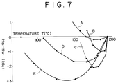
- Figure 7 is a graph showing the temperature characteristic of the value of Hc1 - Hw1 for different types of magneto-optical disks fabricated in a test of the invention.
- Reference is now made to the accompanying drawings and particularly, to Figure 1.
- In Figure 1, there is shown a magneto-optical recording medium M which includes a transparent substrate 1 such as a glass substrate, a polycarbonate substrate or the like, and a magnetic double-
layered film 5 which consists of a first magneticthin film 3 and a second magneticthin film 4, and which is formed on one main surface (lower surface as viewed in the figure) of the substrate 1 through a transparentdielectric layer 2 functioning as a protective film or interference film. In this instance, although the magnetic double-layeredfilm 5 is covered on the surface thereof with a protective film 6, the protective film 6 may not be used. Likewise, the transparentdielectric film 2 may be omitted. In some cases, the magnetic double-layered film 5 may be sandwiched between transparent dielectric films, and a reflection film such as a metallic film may be provided on an opposite side of the transparent substrate 1, thereby enhancing magneto-optical characteristics including, for example, the Kerr angle of rotation. - Both the first magnetic
thin film 3 and the second magneticthin film 4 exhibit vertical magnetic anisotropy. These films are each formed of an amorphous alloy material consisting of at least one of the rare earth (RE) metals such as Tb, Gd and the like, and at least one of the transition metals (TM) such as Fe, Co, Ni and the like. In both cases, the content of the rare earth element is generally in the range of 10 to 40 atomic %, and the content of the transition metal is in the range of 60 to 90 atomic %. Elements other than the rare earth element and the transition metal may be added in small amounts, if necessary, provided that the Curie point Tc1 of the first magneticthin film 3 should be set to be higher than the Curie point Tc2 of the second magneticthin film 4. - In the rare earth element-transition metal amorphous alloy magnetic materials, the magnetic moment of the rare earth element except for Nd or Sm, and the magnetic moment of the transition metal are interacted in an antiparallel fashion. As a result, the ferrimagnetism is developed and the net magnetization is a difference between the sublattice magnetizations of the rare earth element and the transition metal. For example, if the positive and negative values corresponding to the directions of the magnetization are taken into account, the net magnetization is the sum of the respective sublattice magnetizations. In contrast, if Nd or Sm is used as the rare earth element, the magnetic moment of the rare earth element and the magnetic moment of the transition metal are coupled parallel, thereby exhibiting so-called ferromagnetism. In this case, the net magnetization is the sum of the sublattice magnetizations of the rare earth element and the transition metal.
- As stated above, the magneto-optical recording medium of the invention has a fundamental arrangement wherein an exchange-interacted magnetic double-layer film is used as a recording layer. For the purpose of controlling an interfacial magnetic wall energy between the first magnetic
thin film 3 and the second magneticthin film 4, the recording layer may be in the form of a three-layer structure wherein a third magnetic thin film is provided between the magneticthin films thin films 3 and 4 (e.g. not larger than 1 x 10⁻⁶ erg/cm3). By the existence of the third magnetic thin film, the interfacial magnetic wall can be present in stable fashion, thereby permitting the designing margin for characteristics of the magneticthin films - The necessary conditions for performing photo intensity modulation recording in a photo intensity modulation recording system and the magneto-optical recording medium are now described.
- In the photo intensity modulation recording system, as schematically shown in Figure 2 wherein the respective states of magnetization in the first magnetic
thin film 3 and the second magneticthin film 4 are indicated by arrows as corresponding to the temperature T, information is recorded as "0" or "1" corresponding to a state (state A) wherein the directions of magnetization of both magneticthin films - These states are recorded by two-stage heating steps, including application of an external magnetic field Hex, and a laser beam irradiation. The procedure is as described below.
- Initially, while a laser beam is irradiated on a portion, for example, in state A, the intensity and the irradiation time of the laser beam are controlled by modulation in correspondence with recording signals in such a way that the heating temperature from the laser beam is a temperature (first heating temperature T1) within a range of substantially not lower than the Curie point Tc1 of the first magnetic thin film, but at which the magnetization of the second magnetic
thin film 4 is not inverted. By the heating, the first magnetic thin film is turned into a state (state C) where the magnetization is lost. When the temperature of the first magneticthin film 3 and the second magneticthin film 4 is lowered down to the Curie point Tc1 of the first magneticthin film 3 after completion of the heating, magnetization is developed in the first magneticthin film 3. At this time, when the exchange-interacting force with the second magneticthin film 4 is set as predominant, the direction of the magnetization of the first magneticthin film 3 is in conformity with and the same as the direction of the magnetization of the second magneticthin film 4. Accordingly, the magnetic double-layer film 5 results in state A and, for example, the information "0" is recorded. - Then, when the heating temperature is changed to a temperature (i.e. a second heating temperature, T2) which is not lower than the first heating temperature T1, and at which the magnetization of the second magnetic
thin film 4 is inverted by application of an external magnetic field Hex, the first magnetic thin film loses its magnetization. At the same time, the second magneticthin film 4 is converted into state D where its magnetization is inverted. After completion of the heating, when the temperature of the first and second magneticthin films thin film 3, the first magneticthin film 3 is in a state (state E) where the magnetization of thefilm 3 is arranged in a direction opposite to that of state A by the exchange-interaction force with the second magneticthin film 4. At this stage, when the direction of the magnetization of the second magnetic thin film is inverted in the vicinity of room temperature TR by application of an external sub-magnetic field Hsub, which is in a direction opposite to that of the external magnetic field Hex, there appears a magnetized state where amagnetic wall 7 is produced between the first magneticthin film 3 and the second magneticthin film 4, or a state where only the direction of the magnetization of the first magnetic thin film is opposite to that of state A. By this, the magnetic double-layer film 5 is in state B and, for example, the information "1" is recorded. - It will be noted that Figure 2 illustrates the principle using a transition metal sublattice-rich (TM-rich) composition at room temperature. With the case using a rare earth element sublattice-rich (RE-rich) composition at room temperature, because of the compensating point, the direction of the total magnetization is changed from an upward direction (↑) in the figure to a downward direction (↓) during the course of transfer, for example from state C to state D. Accordingly, the direction of the external magnetic field Hex has to be changed to an upward direction (↑) as viewed in the figure. More particularly, with the rare earth element sublattice-rich (RE-rich) composition, the external magnetic field Hex, and the external sub-magnetic field Hsub, have to be the same with respect to the direction.
- In the photo intensity modulation recording system, information is recorded as "0" or "1", corresponding to state A or B respectively. Moreover, overwriting on the information is possible irrespective of the states A and B. More particularly, when the medium is heated to the first heating temperature T1, or the second heating temperature T2, in either state A or state B, state C invariably results. Accordingly, selection of the heating temperature T1 or T2 makes it possible to rewrite state A or B through the above-described procedure, irrespective of the original state being in state A or B.
- For ensuring overwriting in the photo intensity modulation recording system, various characteristic requirements for the first and second magnetic
thin films thin films - In the magneto-optical recording medium of the photo intensity modulation recording system, an exchange energy works at the interface of the built-up layer of the first magnetic
thin film 3 and the second magneticthin film 4, by which themagnetic wall 7 is established in state B. The interfacial magnetic wall energy σw is expressed according to the equation
thin film 3 and the second magneticthin film 4, and K1 and K2 are, respectively, vertical magnetic anisotropy constants of the first magneticthin film 3 and the second magneticthin film 4. - A first necessary condition for overwriting is not to cause the transfer from state B to state A at room temperatures ranging from -20°C to 60°C. This condition at room temperature is expressed as follows:

- A second necessary condition is not to cause the transfer from state B to state E. This condition at room temperature is expressed as follows:

- In addition, in state E, the first magnetic thin film has not to be inverted by the external sub-magnetic field Hsub. This is a third necessary condition. For this purpose, the following inequality (6) has to be satisfied at room temperature:

- The symbols "+" and "-" in the left side of the inequality (6) are intended to mean that when the first magnetic
thin film 3 is a rare earth element-rich film and the second magneticthin film 4 is a transition metal-rich film, "+" is used, and when the first and second magnetic thin films are both a transition metal-rich film, "-" is used. - In order to cause the transfer from state E to state B, the following inequality has to be satisfied at room temperature:

- To cause the transfer from state C to state A when the heating temperature is in the vicinity of the Curie point, Tc1, of the first magnetic
thin film 3 or to permit the direction of magnetization of the first magneticthin film 3 in alignment with the direction of magnetization of the second magnetic thin film, the following condition in the vicinity of the Curie point, Tc1, should be satisfied:
- In order not to cause the transfer of from state C to state E, the following condition has to be satisfied in the vicinity of the Curie point Tc1:

- In the above inequalities, Hw1 and Hw2 are, respectively, a member of an exchange force from the other layer and are, respectively, those values defined in the equations (4) and (5). Hc1 is a coercive force, Ms1 is a saturation magnetization, and h1 is a thickness of the first magnetic thin film. Hc2 is a coercive force, Ms2 is a saturation magnetization, and h2 is a thickness of the second magnetic thin film. σw2 is an interfacial magnetic wall energy, Hex is an external magnetic field which is applied at the time of recording, and Hsub is an external sub-magnetic field applied in a direction opposite to the external magnetic field.
- In the photo intensity modulation recording system, the magneto-optical recording medium should satisfy the above necessary conditions. Further, whether smooth overwriting proceeds or not depends on whether the transfer operation is effected in stable fashion. The transfer operation means that when the direction of the sublattice magnetization of, for example, Fe in the first magnetic
thin film 3 is antiparallel with that of the second magneticthin film 4, the direction of the magnetization of the first magneticthin film 3 is inverted to conform with the direction of the magnetization of the second magnetic thin film. This inversion should not be influenced with the direction of a magnetic field which is externally applied. - Assuming this operation with regard to a static inversional magnetic field characteristic, there is obtained a graph shown in Figure 3. In this figure, there is shown a temperature change of the inversional magnetic field of the first magnetic
thin film 3, expressing the sum (Hc1 - Hw1) of the coercive force Hc1 inherent to the first magnetic thin film and a component of the exchange force, and Hw1 from the other magnetic thin film. - As will be apparent from Figure 3, the value of Hc1 - Hw1 is lowered as the temperature rises. Over a certain temperature, the value is changed to a minus side. The conditions for realizing the transfer are as shown in the inequality (8), which is satisfied for the first time when the value of Hc1 - Hw1 in Figure 3 is changed to the minus side.
- Accordingly, importance is considered to be placed on the shape of a portion projecting toward the minus side of the curve of the Hc1 - Hw1 values. Two parameters which are considered to determine such a shape are defined for evaluation of a magneto-optical recording medium.
- One of the defined parameters is a temperature at which Hc1 - Hw1 = 0. This temperature is taken as T0. Another parameter is a minimum value of Hc1, - Hw1, which is taken as ΔHmax. It will be noted that this value is handled as a negative value when the value of Hw1 - Hc1 appears at the same side where Hw1 + Hc1 appears (relative to a zero magnetic field).
- Electric signal characteristics of a magneto-optical recording medium are checked using the temperature To, and the minimum value ΔHmax as the parameters. Electrical characteristics which are considered to correspond to these parameters are a maximum value of readout power Prmax, and a minimum value of an external magnetic field for recording Hmax, under which the transfer operation proceeds in stable fashion. The former value especially indicates a limit of laser power at the time of readout. If the laser power is increased to exceed such a value, recorded information will be lost.
- Figure 4 shows the interrelation between the temperature To, and the maximum readout power value Prmax, and Figure 5 shows the interrelation between the minimum value ΔHmax of the Hc1 - Hw1 value and the maximum external magnetic field for recording Hmax.
- As will be apparent from these figures, these interrelations are substantially linear, from which it will be understood that the measurements of the temperature To, and the minimum value ΔHmax, which are the characteristics of the magnetic thin films of the magneto-optical recording medium, ensure supposition of the maximum readout power value Prmax, which is an electric signal characteristic, and the maximum value of the external magnetic field for recording Hmax.
- The maximum value of the readout power Prmax has a lower limit, and if Prmax is too low, transfer (erasure) takes place at low temperatures, with an attendant problem of the reliability at the time of reproduction. Accordingly, the temperature To should preferably be 100°C at the lowest. When the temperature To is set at a level of not lower than 100°C, very stable readout becomes possible, provided that information is reproduced at a readout or reproduction power level of not higher than 2.0 mW. If the temperature rise in a drive apparatus is 60°C, reproduction to a level of 1.0 mW becomes possible. The upper limit is within a range of not exceeding the Curie point Tc1 of the first magnetic
thin film 3. In order to make a wide margin, a temperature of Tc1 -30°C is preferred. - The maximum external magnetic field value Hmax does not directly take part in the transfer operation, but recording characteristics and particularly C/N are varied depending on the maximum value Hmax. A higher value is better.
- For instance, as shown in Figure 6, when the first magnetic thin film is changed to different thicknesses of 200 angstroms (solid line), 300 angstroms (broken line) and 400 angstroms (dot-and-dash line), the C/N characteristic is varied. The C/N characteristic becomes maximum at a point indicated by arrow Y for 300 angstroms, and at a point indicated by arrow X for 400 angstroms. The point indicated by arrow X or Y is the maximum value Hmax of the external magnetic field. Over the point, the transfer does not proceed in stable fashion, with C/N being gradually degraded.
- Assuming that the C/N value should be at least 47 to 48 dB, the lowest external magnetic field necessary for recording is 370 oersteds based on judgment from the C/N value. Thus, the maximum value Hmax of the external magnetic field should be not smaller than 370 oersteds. In order to attain this level of the maximum value Hmax of not smaller than 370 oersteds, it will be seen from Figure 5 to make the minimum value of ΔHmax of Hc1 - Hw1 at a level of not larger than -500 oersteds (i.e. an absolute value of not lower than 500 oersteds).
- Thus, proper selection of the temperature To at which Hc1 -Hw1 = 0 and the minimum value ΔHmax of Hc1 - Hw1 ensures formation of a magneto-optical recording medium which has good electric signal characteristics.
- The temperature To at which Hc1 - Hw1 = 0 and the minimum value ΔHmax of Hc1 - Hw1 can be respectively set within the ranges defined before by controlling the compositions and the thicknesses of the first magnetic
thin film 3, the second magneticthin film 4 and, optionally, the third magnetic thin film provided as an intermediate layer. - Magneto-optical disks were made to inspect the relationships stated earlier.
- Magneto-optical disks A to E were fabricated and each had a three-layer structure having an intermediate layer. In these magneto-optical disks, the first magnetic thin film and the second magnetic thin film had, respectively, common compositions and thicknesses. More particularly, the first magnetic thin film has a composition of Tb20(Fe91Co5Cr4)80, a coercive force of not lower than 25 KOe at room temperature, a Curie point of 170°C, and a thickness of 300 angstroms. On the other hand, the second magnetic thin film had a composition of (Gd75Tb25)26(Fe66CO30Cr6)74, a coercive force of not lower than 3 KOe at room temperature, a compensating temperature of 200°C, a Curie point of not lower than 300°C, and a thickness of 800 angstroms.
- In these magneto-optical disks, the composition and thickness of the intermediate layer (third magnetic thin film) were changed to vary the temperature To at which Hc1 - Hw1 = 0 and the minimum value ΔHmax of Hc1 - Hw1. The composition and thickness of the intermediate layer in the respective magneto-optical disks are shown in the Table below:
Table Intermediate Layer Composition Thickness (angstroms) Disk A Gd45(Fe91Co5Cr4)55 200 Disk B Gd40(Fe91CO5Cr4)60 100 Disk C Gd32(Fe91Co5Cr4)68 100 Disk D Gd32(Fe91Co5Cr4)68 40 Disk E Gd28(Fe91Co5Cr4)72 50 - In Figure 7, there is shown the temperature change of Hc1 -Hw1 of the respective magneto-optical disks.
- Attention is now paid to To and ΔHmax of the respective magneto-optical disks. The ΔHmax is about -3000 Oe for the disk E, about -2000 Oe for the disks C and D, about -1000 Oe for the disk B, and about -200 Oe for the disk A. The value of To is about 170°C for the disks A and B, about 160°C for the disk C, about 100°C for the disk D, and about 60°C for the disk E.
- These magneto-optical disks were set in a recording and reproducing apparatus to check overwriting characteristics. The checked characteristics include laser power Prmax at which a transfer operation (erasing operation) starts, and a maximum value Hmax of an external magnetic field at which the transfer can be normally performed. These characteristics are indices as to whether or not the transfer, which is the most important operation during overwriting, proceeds smoothly.
- From this point of view, Prmax is not less than 4 mW for the disks B and C and about 2 mW for the disk D, within which information was not lost when reproduced. In contrast, Prmax was not held for the disk E by which recorded data were erased by the action of the reproduction power.
- With regard to the maximum external magnetic field value Hmax at which the transfer is normally operated, its value is not less than 800 Oe for the disks C and D. With the disk B, a value of 500 Oe is ensured. Thus, record signals with a good C/N value can be obtained. In contrast, with the disk A, a good C/N value could not be obtained.
- As will be apparent from the foregoing description, the magneto-optical recording medium of the invention not only satisfies the necessary conditions for carrying out the photo intensity modulation recording system, but also optimizes the shape of a portion projecting toward the minus side of a curve which is drawn with the values of Hc1 - Hw1 (= - σw/2Ms1h1 + Hc1). Thus, very stable readout and transfer operations are possible with a satisfactory C/N value.
- Although various minor changes and modifications might be proposed by those skilled in the art, it will be understood that we wish to include within the claims of the patent warranted hereon all such changes and modifications as reasonably come within our contribution to the art.
Claims (7)
- A magneto-optical recording medium of the type which comprises, on a transparent substrate, a first magnetic thin film and a second magnetic thin film magnetically coupled with each other to form a built-up layer, and wherein information signals are rewriteable by control of a heating temperature, wherein when the first magnetic thin film has a Curie point Tc1, a coercive force Hc1, a saturation magnetization Ms1, and a thickness h1, the second magnetic thin film has a Curie point Tc2, a coercive force Hc2, a saturation magnetization Ms2, and a thickness h2, and wherein a magnetic wall energy is σw, an external magnetic field applied at the time of recording is Hex, and an external sub-magnetic field is Hsub, the following relationships are satisfied at room temperature





characterized by
a temperature To at which - σw/2Ms1h1 + Hc1 = 0 being within a range of 100°C ≤ To < Tc1 and a minimum value ΔHmax of - σw/2Ms1h1 + Hc1 being not larger than -500 oersteds. - A magneto-optical recording medium according to claim 1 wherein said first magnetic thin film and said second magnetic thin film are respectively made of amorphous alloys of from 10 to 40 atomic percent of at least one rare earth element and from 60 to 90 atomic percent of at least one transition metal, provided that the Curie point Tc2 of said second magnetic thin film is higher than the Curie point Tc1 of said first magnetic thin film .
- A magneto-optical recording medium according to claim 1 further comprising a third magnetic thin film provided between said first magnetic thin film and said second magnetic thin film.
- A magneto-optical recording medium according to claim 3 wherein said third magnetic thin film has an in-plane magnetic anisotropy.
- A magneto-optical recording medium according to claim 3 wherein said third magnetic thin film has a vertical magnetic anisotropy which is smaller than vertical magnetic anisotropies of said first magnetic thin film and said second magnetic thin film.
- A magneto-optical recording medium according to claim 5 wherein the vertical magnetic anisotropy of said third magnetic thin film is not larger than 1 x 10⁻⁶ erg/cm3.
- A magneto-optical recording medium according to claim 1 further comprising a transparent dielectric film provided between said transparent substrate and said first magnetic thin film, and a protective layer formed on said second magnetic thin film.
Applications Claiming Priority (4)
| Application Number | Priority Date | Filing Date | Title |
|---|---|---|---|
| JP411664/90 | 1990-12-19 | ||
| JP41166490 | 1990-12-19 | ||
| JP72199/91 | 1991-03-13 | ||
| JP3072199A JP2910287B2 (en) | 1990-12-19 | 1991-03-13 | Magneto-optical recording medium |
Publications (2)
| Publication Number | Publication Date |
|---|---|
| EP0491337A1 EP0491337A1 (en) | 1992-06-24 |
| EP0491337B1 true EP0491337B1 (en) | 1996-11-20 |
Family
ID=26413328
Family Applications (1)
| Application Number | Title | Priority Date | Filing Date |
|---|---|---|---|
| EP91121557A Expired - Lifetime EP0491337B1 (en) | 1990-12-19 | 1991-12-16 | Magneto-optical recording medium |
Country Status (3)
| Country | Link |
|---|---|
| EP (1) | EP0491337B1 (en) |
| JP (1) | JP2910287B2 (en) |
| DE (1) | DE69123225T2 (en) |
Families Citing this family (1)
| Publication number | Priority date | Publication date | Assignee | Title |
|---|---|---|---|---|
| US5903526A (en) * | 1996-09-20 | 1999-05-11 | Victor Company Of Japan, Ltd. | Magneto-optical recording medium having multiple magnetic layers |
Citations (2)
| Publication number | Priority date | Publication date | Assignee | Title |
|---|---|---|---|---|
| EP0257530A2 (en) * | 1986-08-20 | 1988-03-02 | Sony Corporation | Thermo-magnetic recording method applying power modulated laser on magnetically coupled double layer structure of perpendicular anisotropy film |
| EP0352548A2 (en) * | 1988-07-13 | 1990-01-31 | Sony Corporation | Thermo-magnetic recording method |
Family Cites Families (2)
| Publication number | Priority date | Publication date | Assignee | Title |
|---|---|---|---|---|
| JP2830018B2 (en) * | 1989-03-01 | 1998-12-02 | 株式会社ニコン | Magneto-optical recording medium |
| JPH02265058A (en) * | 1989-04-06 | 1990-10-29 | Mitsui Petrochem Ind Ltd | Magneto-optical recording medium and its initializing method |
-
1991
- 1991-03-13 JP JP3072199A patent/JP2910287B2/en not_active Expired - Fee Related
- 1991-12-16 EP EP91121557A patent/EP0491337B1/en not_active Expired - Lifetime
- 1991-12-16 DE DE1991623225 patent/DE69123225T2/en not_active Expired - Fee Related
Patent Citations (2)
| Publication number | Priority date | Publication date | Assignee | Title |
|---|---|---|---|---|
| EP0257530A2 (en) * | 1986-08-20 | 1988-03-02 | Sony Corporation | Thermo-magnetic recording method applying power modulated laser on magnetically coupled double layer structure of perpendicular anisotropy film |
| EP0352548A2 (en) * | 1988-07-13 | 1990-01-31 | Sony Corporation | Thermo-magnetic recording method |
Non-Patent Citations (1)
| Title |
|---|
| Patent abstracts of Japan, unexamined applications, P field, vol. 12, no. 271, July 28, 1988 page 21 P 736 * |
Also Published As
| Publication number | Publication date |
|---|---|
| JPH06215426A (en) | 1994-08-05 |
| DE69123225T2 (en) | 1997-06-12 |
| DE69123225D1 (en) | 1997-01-02 |
| JP2910287B2 (en) | 1999-06-23 |
| EP0491337A1 (en) | 1992-06-24 |
Similar Documents
| Publication | Publication Date | Title |
|---|---|---|
| EP0352548B1 (en) | Thermo-magnetic recording method | |
| EP0257530B2 (en) | Thermo-magnetic recording method applying power modulated laser on magnetically coupled double layer structure of perpendicular anisotropy film | |
| EP0258978B1 (en) | Magnetooptical recording medium allowing overwriting with two or more magnetic layers and recording method utilizing the same | |
| JP2910250B2 (en) | Magneto-optical recording medium | |
| JPS60177455A (en) | magneto-optical recording medium | |
| JP2579631B2 (en) | Magneto-optical recording method | |
| US5783300A (en) | Magnetooptical recording medium allowing overwriting with two or more magnetic layers and recording method utilizing the same | |
| EP0491337A1 (en) | Magneto-optical recording medium | |
| JP2829970B2 (en) | Thermomagnetic recording medium | |
| JP3208275B2 (en) | Magneto-optical recording medium | |
| US6028824A (en) | Magnetooptical recording medium allowing overwriting with two or more magnetic layers | |
| JP2680586B2 (en) | Magneto-optical storage medium | |
| US5903526A (en) | Magneto-optical recording medium having multiple magnetic layers | |
| EP0428946B1 (en) | Magneto-optic recording medium | |
| US6660404B2 (en) | Magnetooptical recording medium including a connection layer that is non-magnetic by itself at room temperature but can be induced to exhibit magnetism when in contact with a magnetic layer | |
| JP2805070B2 (en) | Thermomagnetic recording method | |
| JP3381960B2 (en) | Magneto-optical recording medium | |
| JP2903729B2 (en) | Magneto-optical recording medium | |
| JPH0612711A (en) | Magneto-optical recording medium | |
| EP0780841A2 (en) | Magnetooptical recording medium using a magnetic phase transformation material and a recording method using the medium | |
| JP3490138B2 (en) | Magneto-optical recording medium | |
| JP3395189B2 (en) | Magneto-optical recording method | |
| JPH06309710A (en) | Magneto-optical recording medium | |
| JPH05234163A (en) | Magneto-optical recording medium | |
| JP2000339788A (en) | Magneto-optical recording medium and reproducing method thereof |
Legal Events
| Date | Code | Title | Description |
|---|---|---|---|
| PUAI | Public reference made under article 153(3) epc to a published international application that has entered the european phase |
Free format text: ORIGINAL CODE: 0009012 |
|
| AK | Designated contracting states |
Kind code of ref document: A1 Designated state(s): DE FR GB |
|
| 17P | Request for examination filed |
Effective date: 19921130 |
|
| 17Q | First examination report despatched |
Effective date: 19950210 |
|
| GRAG | Despatch of communication of intention to grant |
Free format text: ORIGINAL CODE: EPIDOS AGRA |
|
| GRAG | Despatch of communication of intention to grant |
Free format text: ORIGINAL CODE: EPIDOS AGRA |
|
| GRAG | Despatch of communication of intention to grant |
Free format text: ORIGINAL CODE: EPIDOS AGRA |
|
| GRAH | Despatch of communication of intention to grant a patent |
Free format text: ORIGINAL CODE: EPIDOS IGRA |
|
| GRAH | Despatch of communication of intention to grant a patent |
Free format text: ORIGINAL CODE: EPIDOS IGRA |
|
| GRAA | (expected) grant |
Free format text: ORIGINAL CODE: 0009210 |
|
| AK | Designated contracting states |
Kind code of ref document: B1 Designated state(s): DE FR GB |
|
| REF | Corresponds to: |
Ref document number: 69123225 Country of ref document: DE Date of ref document: 19970102 |
|
| ET | Fr: translation filed | ||
| PLBE | No opposition filed within time limit |
Free format text: ORIGINAL CODE: 0009261 |
|
| STAA | Information on the status of an ep patent application or granted ep patent |
Free format text: STATUS: NO OPPOSITION FILED WITHIN TIME LIMIT |
|
| 26N | No opposition filed | ||
| PGFP | Annual fee paid to national office [announced via postgrant information from national office to epo] |
Ref country code: FR Payment date: 20011212 Year of fee payment: 11 |
|
| PGFP | Annual fee paid to national office [announced via postgrant information from national office to epo] |
Ref country code: GB Payment date: 20011219 Year of fee payment: 11 |
|
| REG | Reference to a national code |
Ref country code: GB Ref legal event code: IF02 |
|
| PGFP | Annual fee paid to national office [announced via postgrant information from national office to epo] |
Ref country code: DE Payment date: 20020109 Year of fee payment: 11 |
|
| PG25 | Lapsed in a contracting state [announced via postgrant information from national office to epo] |
Ref country code: GB Free format text: LAPSE BECAUSE OF NON-PAYMENT OF DUE FEES Effective date: 20021216 |
|
| PG25 | Lapsed in a contracting state [announced via postgrant information from national office to epo] |
Ref country code: DE Free format text: LAPSE BECAUSE OF NON-PAYMENT OF DUE FEES Effective date: 20030701 |
|
| GBPC | Gb: european patent ceased through non-payment of renewal fee |
Effective date: 20021216 |
|
| PG25 | Lapsed in a contracting state [announced via postgrant information from national office to epo] |
Ref country code: FR Free format text: LAPSE BECAUSE OF NON-PAYMENT OF DUE FEES Effective date: 20030901 |
|
| REG | Reference to a national code |
Ref country code: FR Ref legal event code: ST |