EP0490847B1 - Tunnel boring machine - Google Patents
Tunnel boring machine Download PDFInfo
- Publication number
- EP0490847B1 EP0490847B1 EP91850286A EP91850286A EP0490847B1 EP 0490847 B1 EP0490847 B1 EP 0490847B1 EP 91850286 A EP91850286 A EP 91850286A EP 91850286 A EP91850286 A EP 91850286A EP 0490847 B1 EP0490847 B1 EP 0490847B1
- Authority
- EP
- European Patent Office
- Prior art keywords
- shaft
- tunnel
- boring head
- shell
- boring
- Prior art date
- Legal status (The legal status is an assumption and is not a legal conclusion. Google has not performed a legal analysis and makes no representation as to the accuracy of the status listed.)
- Expired - Lifetime
Links
- 239000012530 fluid Substances 0.000 claims description 3
- 239000002360 explosive Substances 0.000 description 1
Images
Classifications
-
- E—FIXED CONSTRUCTIONS
- E21—EARTH OR ROCK DRILLING; MINING
- E21D—SHAFTS; TUNNELS; GALLERIES; LARGE UNDERGROUND CHAMBERS
- E21D9/00—Tunnels or galleries, with or without linings; Methods or apparatus for making thereof; Layout of tunnels or galleries
- E21D9/10—Making by using boring or cutting machines
- E21D9/1093—Devices for supporting, advancing or orientating the machine or the tool-carrier
-
- F—MECHANICAL ENGINEERING; LIGHTING; HEATING; WEAPONS; BLASTING
- F16—ENGINEERING ELEMENTS AND UNITS; GENERAL MEASURES FOR PRODUCING AND MAINTAINING EFFECTIVE FUNCTIONING OF MACHINES OR INSTALLATIONS; THERMAL INSULATION IN GENERAL
- F16C—SHAFTS; FLEXIBLE SHAFTS; ELEMENTS OR CRANKSHAFT MECHANISMS; ROTARY BODIES OTHER THAN GEARING ELEMENTS; BEARINGS
- F16C2300/00—Application independent of particular apparatuses
- F16C2300/10—Application independent of particular apparatuses related to size
- F16C2300/14—Large applications, e.g. bearings having an inner diameter exceeding 500 mm
Definitions
- the present invention relates to a tunnel boring machine, i.e. a machine by means of which a tunnel is bored to full area without using explosives.
- the present invention which is defined in the subsequent claim, aims at achieving a tunnel boring machine which admits the mounting of boring heads with comparatively different diameters on the same driving shaft. This is achieved by, contrary to prior art, journalling the driving shaft for the boring head adjacent to the boring head only in a bearing which is only intended for radial forces. Through this a substantial diameter reduction of the design is obtained directly behind the boring head. The axial forces are transferred from the machine housing via bearings at the rear end of the machine to the rotational shaft for the boring head and from there to the boring head.
- the tunnel boring machine shown in the drawing comprises a machine housing 1 which by means of hydraulic cylinders 15 and clamping shoes 16 is clampable in a tunnel 2.
- a shell 3 is movable to-and-fro in the machine housing and prevented from rotation about its longitudinal axis by the machine housing.
- a shaft 4 is rotatably journalled.
- Shaft 4 carries at its front end 5 a boring head 6 which is provided with a number of cutters 7, one shown, for the working of a tunnel front 11.
- Shaft 4 is at its front end journalled, by means of a bearing 12, in the shown example a spherical roller bearing, which is only intended for the taking up of radial forces, in shell 3.
- Shell 3 is supported adjacent to bearing 12 by a not shown support foot.
- the drawing shows the tunnel boring machine from above making the support foot obscured.
- Shell 3 is at its end 7 far from the boring head provided with a gear box 8 on which a number of driving motors 9 are arranged.
- Shaft 4 is by means of bearings 13,14, in the shown example conical roller bearings,journalled in the gear box 8. These bearings are intended for the taking up of both radial and axial forces.
- the outgoing shafts of the driving motors transfer torque via the gear wheel 18 to shaft 4.
- gear box 8 is provided with two hydraulic cylinders 19 which carry not shown support feet.
- boring head 6 In order to adjust the machine to different tunnel diameters boring head 6 can be exchanged, driving motors 9 can be exchanged or the number of driving motors can be changed. Furthermore, the number of clamping shoes 16 can be adjusted to the transferred torque.
Landscapes
- Engineering & Computer Science (AREA)
- Mining & Mineral Resources (AREA)
- Environmental & Geological Engineering (AREA)
- Life Sciences & Earth Sciences (AREA)
- General Life Sciences & Earth Sciences (AREA)
- Geochemistry & Mineralogy (AREA)
- Geology (AREA)
- Earth Drilling (AREA)
- Excavating Of Shafts Or Tunnels (AREA)
Abstract
Description
- The present invention relates to a tunnel boring machine, i.e. a machine by means of which a tunnel is bored to full area without using explosives.
- In a prior art tunnel boring machine, see GB-A-1 295 152, the driving shaft for the boring head is journalled in both radial and thrust bearings at its front end. In order to handle the large thrusts the thrust bearing must have a comparatively large diameter.
- It has long been a desire to be able to construct machines of the above mentioned kind for different tunnel diameters and thereby use module designs which are the same for the different tunnel diameters. Machines designed according to these ideas would be substantially cheaper because fewer parts need be specially designed for individual machines. Machines which comply with the above mentioned desire must have a driving shaft for the boring head which can stand the torque which the biggest machine requires. This gives a large diameter. At the same time the bearing adjacent to the boring head must admit passage, for instance for exchange of boring tools, in the smallest contemplated tunnel diameter.
- The present invention, which is defined in the subsequent claim, aims at achieving a tunnel boring machine which admits the mounting of boring heads with comparatively different diameters on the same driving shaft. This is achieved by, contrary to prior art, journalling the driving shaft for the boring head adjacent to the boring head only in a bearing which is only intended for radial forces. Through this a substantial diameter reduction of the design is obtained directly behind the boring head. The axial forces are transferred from the machine housing via bearings at the rear end of the machine to the rotational shaft for the boring head and from there to the boring head.
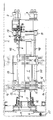
- An embodiment of the invention is described below with reference to the accompnying drawing which schematically shows a section through a tunnel boring machine according to the invention.
- The tunnel boring machine shown in the drawing comprises a
machine housing 1 which by means ofhydraulic cylinders 15 andclamping shoes 16 is clampable in atunnel 2. Ashell 3 is movable to-and-fro in the machine housing and prevented from rotation about its longitudinal axis by the machine housing. In shell 3 ashaft 4 is rotatably journalled. Shaft 4 carries at its front end 5 aboring head 6 which is provided with a number ofcutters 7, one shown, for the working of a tunnel front 11.Shaft 4 is at its front end journalled, by means of abearing 12, in the shown example a spherical roller bearing, which is only intended for the taking up of radial forces, inshell 3.Shell 3 is supported adjacent to bearing 12 by a not shown support foot. The drawing shows the tunnel boring machine from above making the support foot obscured. Shell 3 is at itsend 7 far from the boring head provided with agear box 8 on which a number ofdriving motors 9 are arranged.Shaft 4 is by means ofbearings gear box 8. These bearings are intended for the taking up of both radial and axial forces. The outgoing shafts of the driving motors transfer torque via thegear wheel 18 toshaft 4. In order to pressboring head 6 against the tunnel front 11 a number ofpressure fluid cylinders 10 provided withpiston rods 48 are arranged betweenmachine housing 1 andshaft 4 viagear box 8.Gear box 8 is provided with twohydraulic cylinders 19 which carry not shown support feet. - In order to adjust the machine to different tunnel diameters
boring head 6 can be exchanged, drivingmotors 9 can be exchanged or the number of driving motors can be changed. Furthermore, the number ofclamping shoes 16 can be adjusted to the transferred torque.
Claims (1)
- Tunnel boring machine comprising a machine housing (1) which is clampable in a tunnel (2), a shell (3) movable to-and-fro in the machine housing, a shaft (4) rotatably journalled in said shell (3), said shaft (4) at one (5) of its ends carrying a boring head (6), said shell (3) at its from the boring head (6) directed end (7) being provided with a gear box (8) on which a number of driving motors (9) are arranged, and a number of pressure fluid cylinders (10) being arranged between said machine housing (1) and said shaft (4) in order to press said boring head (6) against a tunnel front (11), characterized in that said shaft (4) adjacent to the boring head (6) is journalled in said shell (3) only by means of a bearing (12) intended to only take up radial forces, at said gear box (8) is journalled by means of bearings (13,14) which take up both radial and axial forces and that said pressure fluid cylinders (10) are arranged between said machine housing (1) and said gear box (8).
Applications Claiming Priority (2)
| Application Number | Priority Date | Filing Date | Title |
|---|---|---|---|
| SE9003979 | 1990-12-13 | ||
| SE9003979A SE466065B (en) | 1990-12-13 | 1990-12-13 | tunnel boring machine |
Publications (2)
| Publication Number | Publication Date |
|---|---|
| EP0490847A1 EP0490847A1 (en) | 1992-06-17 |
| EP0490847B1 true EP0490847B1 (en) | 1995-06-14 |
Family
ID=20381183
Family Applications (1)
| Application Number | Title | Priority Date | Filing Date |
|---|---|---|---|
| EP91850286A Expired - Lifetime EP0490847B1 (en) | 1990-12-13 | 1991-11-20 | Tunnel boring machine |
Country Status (9)
| Country | Link |
|---|---|
| US (1) | US5228752A (en) |
| EP (1) | EP0490847B1 (en) |
| JP (1) | JPH06299786A (en) |
| AT (1) | ATE123844T1 (en) |
| AU (1) | AU647568B2 (en) |
| CA (1) | CA2056763A1 (en) |
| DE (1) | DE69110433T2 (en) |
| SE (1) | SE466065B (en) |
| ZA (1) | ZA919503B (en) |
Families Citing this family (7)
| Publication number | Priority date | Publication date | Assignee | Title |
|---|---|---|---|---|
| US5641207A (en) * | 1995-08-15 | 1997-06-24 | Ringgold Mines, Inc. | Mining machine |
| DE19722000A1 (en) * | 1997-05-27 | 1998-12-03 | Wirth Co Kg Masch Bohr | Tunnel boring machine |
| SE526134C2 (en) * | 2003-11-21 | 2005-07-12 | Atlas Copco Rock Drills Ab | Drilling rig for production drilling in confined spaces |
| CN106285708B (en) * | 2016-09-18 | 2018-03-27 | 中铁隧道集团有限公司 | A kind of rotatable spoke for cutter head of shield machine |
| CN107120122A (en) * | 2017-05-15 | 2017-09-01 | 东北大学 | A kind of pusher push-bench hemispherical knife head device |
| CN108982207B (en) * | 2018-06-08 | 2020-08-25 | 东南大学 | Segmentation unloading excavating device for simulating rock tunnel segmentation excavation |
| CN111550257A (en) * | 2020-04-29 | 2020-08-18 | 吉林省维尔特隧道装备有限公司 | TBM shaft type single-edge hob and cutter |
Family Cites Families (6)
| Publication number | Priority date | Publication date | Assignee | Title |
|---|---|---|---|---|
| US3383138A (en) * | 1966-04-11 | 1968-05-14 | S & M Constructors Inc | Tunneling machine with stepper advance and articulated torque arms |
| US3640573A (en) * | 1969-10-06 | 1972-02-08 | Smith International | Tunneling machine |
| SU538133A1 (en) * | 1974-03-15 | 1976-12-05 | Донецкий государственный проектно-конструкторский и экспериментальный институт комплексной механизации шахт Донгипроуглемаш | Heading machine |
| US4189186A (en) * | 1978-06-12 | 1980-02-19 | Jarva, Inc. | Tunneling machine |
| US4371211A (en) * | 1980-12-11 | 1983-02-01 | Jarva, Inc. | Tunnel boring machine and method of operating same |
| US5125719A (en) * | 1991-03-29 | 1992-06-30 | Larry Snyder | Tunnel boring machine and method |
-
1990
- 1990-12-13 SE SE9003979A patent/SE466065B/en not_active IP Right Cessation
-
1991
- 1991-11-20 EP EP91850286A patent/EP0490847B1/en not_active Expired - Lifetime
- 1991-11-20 DE DE69110433T patent/DE69110433T2/en not_active Expired - Fee Related
- 1991-11-20 AT AT91850286T patent/ATE123844T1/en not_active IP Right Cessation
- 1991-11-28 JP JP3314827A patent/JPH06299786A/en active Pending
- 1991-12-02 CA CA002056763A patent/CA2056763A1/en not_active Abandoned
- 1991-12-03 ZA ZA919503A patent/ZA919503B/en unknown
- 1991-12-04 US US07/802,334 patent/US5228752A/en not_active Expired - Fee Related
-
1992
- 1992-01-09 AU AU10128/92A patent/AU647568B2/en not_active Ceased
Also Published As
| Publication number | Publication date |
|---|---|
| SE9003979L (en) | 1991-12-09 |
| SE466065B (en) | 1991-12-09 |
| EP0490847A1 (en) | 1992-06-17 |
| US5228752A (en) | 1993-07-20 |
| AU647568B2 (en) | 1994-03-24 |
| ATE123844T1 (en) | 1995-06-15 |
| CA2056763A1 (en) | 1992-06-14 |
| AU1012892A (en) | 1992-06-18 |
| ZA919503B (en) | 1992-08-26 |
| DE69110433D1 (en) | 1995-07-20 |
| JPH06299786A (en) | 1994-10-25 |
| SE9003979D0 (en) | 1990-12-13 |
| DE69110433T2 (en) | 1995-10-12 |
Similar Documents
| Publication | Publication Date | Title |
|---|---|---|
| US4957398A (en) | Two-section tool spindle having a channel for carrying pressurized fluid | |
| US6925694B2 (en) | Tool turret | |
| EP0669208A1 (en) | Shaft mounting and drive for carton blank processing machine | |
| SE443591B (en) | DEVICE FOR CONTINUOUS REVOLUTION OF THE VIBRATION AMPLIANCE WITH A ROTABLE EXCENTER ELEMENT | |
| CN218692585U (en) | Clamping rotary feeding device for cold pilger mill | |
| US5228752A (en) | Tunnel boring machine | |
| JPS5818161B2 (en) | Tokuni Tajiku Kaitenji Douban Tokuni Tajiku Kaitenji Douban | |
| JPH05157043A (en) | Radial piston machine | |
| US20010027674A1 (en) | Rolling unit for a rolling mill for rolling or sizing metal pipes, bars or wires | |
| US7063173B2 (en) | Spindle unit with switchable gear, and method for using the spindle unit | |
| FI91135C (en) | A method of drilling holes in the cylinder liner of a paper machine and the equipment used in the method | |
| US8161860B2 (en) | Rotary cutter and rotary cutting apparatus provided with the rotary cutter | |
| US3587294A (en) | Rotary tube-testing presses | |
| CN201151075Y (en) | Mould rollover unit | |
| JP3268415B2 (en) | Drilling machine | |
| KR20030028431A (en) | Roll support structure of printing device | |
| US4480454A (en) | Skew-rolling mill for reducing solid and hollow cross-sections | |
| US3911550A (en) | Quick-change die and roller assembly | |
| CA2174932A1 (en) | Swashplate machine | |
| US4842080A (en) | Arrangement for mounting of a rotation element in a drilling machine | |
| KR102451398B1 (en) | Infeed power device of flap wheel paper grinder | |
| TW429182B (en) | Lathe and method for turning a work piece on a lathe | |
| JPH0919848A (en) | Swivel indexing device using 3-piece coupling | |
| US5524467A (en) | Method for the inner profiling of tubes or pipes | |
| EP0375642B1 (en) | Tunnel boring machine |
Legal Events
| Date | Code | Title | Description |
|---|---|---|---|
| PUAI | Public reference made under article 153(3) epc to a published international application that has entered the european phase |
Free format text: ORIGINAL CODE: 0009012 |
|
| AK | Designated contracting states |
Kind code of ref document: A1 Designated state(s): AT CH DE FR GB IT LI |
|
| 17P | Request for examination filed |
Effective date: 19921208 |
|
| 17Q | First examination report despatched |
Effective date: 19931125 |
|
| GRAA | (expected) grant |
Free format text: ORIGINAL CODE: 0009210 |
|
| AK | Designated contracting states |
Kind code of ref document: B1 Designated state(s): AT CH DE FR GB IT LI |
|
| REF | Corresponds to: |
Ref document number: 123844 Country of ref document: AT Date of ref document: 19950615 Kind code of ref document: T |
|
| ET | Fr: translation filed | ||
| ITF | It: translation for a ep patent filed | ||
| REF | Corresponds to: |
Ref document number: 69110433 Country of ref document: DE Date of ref document: 19950720 |
|
| PLBE | No opposition filed within time limit |
Free format text: ORIGINAL CODE: 0009261 |
|
| STAA | Information on the status of an ep patent application or granted ep patent |
Free format text: STATUS: NO OPPOSITION FILED WITHIN TIME LIMIT |
|
| 26N | No opposition filed | ||
| PGFP | Annual fee paid to national office [announced via postgrant information from national office to epo] |
Ref country code: FR Payment date: 19981110 Year of fee payment: 8 |
|
| PGFP | Annual fee paid to national office [announced via postgrant information from national office to epo] |
Ref country code: AT Payment date: 19981112 Year of fee payment: 8 |
|
| PGFP | Annual fee paid to national office [announced via postgrant information from national office to epo] |
Ref country code: GB Payment date: 19981120 Year of fee payment: 8 |
|
| PGFP | Annual fee paid to national office [announced via postgrant information from national office to epo] |
Ref country code: DE Payment date: 19981130 Year of fee payment: 8 |
|
| PGFP | Annual fee paid to national office [announced via postgrant information from national office to epo] |
Ref country code: CH Payment date: 19981210 Year of fee payment: 8 |
|
| PG25 | Lapsed in a contracting state [announced via postgrant information from national office to epo] |
Ref country code: GB Free format text: LAPSE BECAUSE OF NON-PAYMENT OF DUE FEES Effective date: 19991120 Ref country code: AT Free format text: LAPSE BECAUSE OF NON-PAYMENT OF DUE FEES Effective date: 19991120 |
|
| PG25 | Lapsed in a contracting state [announced via postgrant information from national office to epo] |
Ref country code: LI Free format text: LAPSE BECAUSE OF NON-PAYMENT OF DUE FEES Effective date: 19991130 Ref country code: CH Free format text: LAPSE BECAUSE OF NON-PAYMENT OF DUE FEES Effective date: 19991130 |
|
| GBPC | Gb: european patent ceased through non-payment of renewal fee |
Effective date: 19991120 |
|
| REG | Reference to a national code |
Ref country code: CH Ref legal event code: PL |
|
| PG25 | Lapsed in a contracting state [announced via postgrant information from national office to epo] |
Ref country code: FR Free format text: LAPSE BECAUSE OF NON-PAYMENT OF DUE FEES Effective date: 20000731 |
|
| PG25 | Lapsed in a contracting state [announced via postgrant information from national office to epo] |
Ref country code: DE Free format text: LAPSE BECAUSE OF NON-PAYMENT OF DUE FEES Effective date: 20000901 |
|
| REG | Reference to a national code |
Ref country code: FR Ref legal event code: ST |
|
| PG25 | Lapsed in a contracting state [announced via postgrant information from national office to epo] |
Ref country code: IT Free format text: LAPSE BECAUSE OF NON-PAYMENT OF DUE FEES;WARNING: LAPSES OF ITALIAN PATENTS WITH EFFECTIVE DATE BEFORE 2007 MAY HAVE OCCURRED AT ANY TIME BEFORE 2007. THE CORRECT EFFECTIVE DATE MAY BE DIFFERENT FROM THE ONE RECORDED. Effective date: 20051120 |