EP0489755B1 - A device for producing a particulate dispersion - Google Patents
A device for producing a particulate dispersion Download PDFInfo
- Publication number
- EP0489755B1 EP0489755B1 EP90911861A EP90911861A EP0489755B1 EP 0489755 B1 EP0489755 B1 EP 0489755B1 EP 90911861 A EP90911861 A EP 90911861A EP 90911861 A EP90911861 A EP 90911861A EP 0489755 B1 EP0489755 B1 EP 0489755B1
- Authority
- EP
- European Patent Office
- Prior art keywords
- duct
- fluid material
- outlet apertures
- dispersion
- outlet
- Prior art date
- Legal status (The legal status is an assumption and is not a legal conclusion. Google has not performed a legal analysis and makes no representation as to the accuracy of the status listed.)
- Expired - Lifetime
Links
Images

Classifications
-
- B—PERFORMING OPERATIONS; TRANSPORTING
- B05—SPRAYING OR ATOMISING IN GENERAL; APPLYING FLUENT MATERIALS TO SURFACES, IN GENERAL
- B05B—SPRAYING APPARATUS; ATOMISING APPARATUS; NOZZLES
- B05B7/00—Spraying apparatus for discharge of liquids or other fluent materials from two or more sources, e.g. of liquid and air, of powder and gas
- B05B7/0012—Apparatus for achieving spraying before discharge from the apparatus
-
- A—HUMAN NECESSITIES
- A61—MEDICAL OR VETERINARY SCIENCE; HYGIENE
- A61M—DEVICES FOR INTRODUCING MEDIA INTO, OR ONTO, THE BODY; DEVICES FOR TRANSDUCING BODY MEDIA OR FOR TAKING MEDIA FROM THE BODY; DEVICES FOR PRODUCING OR ENDING SLEEP OR STUPOR
- A61M11/00—Sprayers or atomisers specially adapted for therapeutic purposes
- A61M11/001—Particle size control
- A61M11/002—Particle size control by flow deviation causing inertial separation of transported particles
-
- A—HUMAN NECESSITIES
- A61—MEDICAL OR VETERINARY SCIENCE; HYGIENE
- A61M—DEVICES FOR INTRODUCING MEDIA INTO, OR ONTO, THE BODY; DEVICES FOR TRANSDUCING BODY MEDIA OR FOR TAKING MEDIA FROM THE BODY; DEVICES FOR PRODUCING OR ENDING SLEEP OR STUPOR
- A61M11/00—Sprayers or atomisers specially adapted for therapeutic purposes
- A61M11/06—Sprayers or atomisers specially adapted for therapeutic purposes of the injector type
Definitions
- THIS INVENTION concerns a device for the production of a substantially uniform dispersion of droplets or particles from a fluid material such as a liquid or solids/liquids suspension, or a particulate free-flowing solid.
- a fluid material such as a liquid or solids/liquids suspension, or a particulate free-flowing solid.
- aerosols or dispersions are widely used in the biological and medical research fields and in inhalation therapy, and are generated by the aerosolisation of the liquid or other particulate substance by an air stream. The efficiency of the process is dependent upon the flow of the material through an orifice or jet.
- a device for producing a particulate dispersion comprising at least one duct to contain a supply of a fluid material to be dispersed such that a surface of the fluid material is established at an open end of the duct, a plurality of outlet apertures communicating with said open end of the duct and directed normal to the longitudinal axis of the duct, and a plurality of pressurised gas jets aligned with the outlet apertures and directed across the surface of the fluid material in the duct to draw fluid material from said surface thereof and to form a dispersion of the fluid material which then passes outwardly through the apertures, characterised in that the cross-sectional area of each outlet aperture is not greater than the area of the surface of fluid material in the duct communicating therewith.
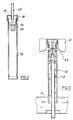
- a device for producing a particulate dispersion comprises a vessel 10 for containing a reservoir 11 of liquid or a liquid/solids suspension.
- the vessel includes a wide outlet duct 12 which in this example is directed upwardly at the top of the vessel.
- a nebuliser assembly comprises an upright tubular duct 13 fixed centrally within the vessel 10 and aligned with the outlet 12, and having its lower open end submerged within the liquid 11.
- Concentrically within the duct 13 is an air line 14 connected externally of the vessel 10 to a supply of pressurised air.
- a body 15 At the top of the air line 14 is a body 15 defining a plurality of air jets 16 which communicate with the air line 14 each having a diverging mouth 17 opening onto the surface of the column of liquid established within the duct 13.
- the assembly of duct 13 and body 15 is closed at its upper end by a sealed plug 18 and cap 19. These latter parts are removable for cleaning.
- Some six to twelve aligned pairs of air jets 16 and apertures 20 may be provided at spaced positions around the circumference of duct 13.
- the pressurised air issuing from jets 16 impinges upon the surface of the liquid of the column within duct 13 and forms a dispersion of droplets of liquid as an aerosol which passes outwardly through apertures 20.
- the sizes of droplets of liquid within the aerosol vary and in the case of water may be between 0.5 ⁇ m and 500 ⁇ m.
- the dimensions of the parts of the assembly illustrated in Fig. 1 in this example, are such that the combined cross-sectional area of the apertures 20 is not greater than and preferably less than the surface area of the liquid, i.e. the cross-sectional area of the annular column of liquid in duct 13, but is greater than the combined cross-sectional area of the air jets 16.
- the liquid/solids are not required to flow through a small constriction and there is no tendency for the apertures 20 to become blocked.
- the droplets in the product aerosol issuing from outlet 12 are typically in the range of 0.5 ⁇ m to 20 ⁇ m.
- the maximum droplet size is determined by the geometry of the apparatus and is inversely related to the level of impaction forces generated by the input pressure applied to the air jets.
- the nebuliser assembly within vessel 10 is modified in that the air line illustrated at 14' enters the assembly from the top, leaving the entire duct 13 free to transport a liquid column of larger cross-sectional area from the reservoir.
- a baffle 21 which surrounds the top of duct 13 and presents, adjacent each outlet aperture 20 a curvilinear or other outwardly diverging surface 22 upon which larger droplets within the dispersion may impinge.
- the high velocity of air flow across the surfaces 22 results in secondary production of small droplets by a re-entrainment of the impacted liquid so that the overall droplet size falls within a similar range to that produced by the apparatus illustrated in Fig. 1, but here aerosol concentration is significantly greater since less of the liquid is returned to the reservoir.
- the maximum droplet size and the extent of secondary aerosol production are determined by the geometry of the apparatus and are inversely and directly related respectively to the input pressure.
- aerosolised droplets will evaporate with time to a new size.
- the extent of evaporation is dependent upon the vapour pressure of the liquid in air. If solutes and/or insoluble particles are present in the liquid, complete evaporation can leave almost dry particles of solute and/or insoluble particles dispersed in the air.
- the air jets 16 may be six in number equidistant around the body 15, and between 0.7 and 1.3 mm in diameter with the outlet apertures 20 between 3 and 6 mm in diameter.
- the cross-sectional area of the duct 13 would accordingly be between 140 sq mm and 420 sq mm.
- increasing the size of the outlet apertures requires an increased air flow to draw liquid upwardly in the column from the reservoir. This may be achieved by increasing the air pressure for a given jet size or by increasing the size of the jets for a given air pressure. It is not essential for all of the air jets or all of the outlet apertures in the apparatus to be of uniform size.
- Combinations of different sized pairs of apertures may be provided and the aligned pairs of air jets and outlet aperture may be at different angles around the nebuliser head so that the aerosol dispersion is distributed throughout an increased volume of space within the apparatus.
- the relative dimensions of the duct 13, jets 16, and outlet apertures 20, may together be scaled up or down to suit the particular requirements of the device.
- the device may be modified by rotating one or more parts of the nebuliser assembly so that, for example, in Fig. 3 the baffle 21 could be rotated or alternatively the air jet assembly may be rotated relative to or in synchronism with a part of the duct 13 containing the outlet apertures 20. Spinning of part or all of the apparatus in this way may be utilised to increase the draw of liquid from the reservoir or the extent of secondary aerosolisation, or in separation applications when a fraction of particles within the aerosol may be separated by centrifugal forces.
- a nebuliser made in accordance with the invention is that materials containing or even in the form of solids may be dispersed without blockage of the apparatus, whilst, at high gas pressures, the particles may emerge from the orifices without excessive physical damage whereby the device may be applied to the dispersion of delicate materials.
- the wall 13 of the duct is preferably circular in cross-section, other shapes may be suitable with commensurate similar configuration of the body 15 containing the air jets 16.
- An additional advantage may be attained by applying reduced pressure at the outlet 12 thus positively to draw larger volumes of the product dispersion from the device.
- a similar effect would result from providing an in-line fan within the vessel. 10 forcing the dispersion through the outlet. In this way, humidification of large gas volumes, or rapid evaporation of liquids may be achieved.
- a typical figure for droplet concentration obtained using a six-jet device with a jet diameter of 1.1mm and an outlet aperture diameter of 4mm, operating at 1.0 bar (15 psi), is 2.2 x 103 cm ⁇ 3 with a mean droplet diameter of 3.53 ⁇ m.
- the droplet concentration increases to, for example, 8.0 x 103 cm ⁇ 3 with a mean diameter of 3.78 ⁇ m.
Landscapes
- Health & Medical Sciences (AREA)
- Veterinary Medicine (AREA)
- Engineering & Computer Science (AREA)
- Biomedical Technology (AREA)
- Heart & Thoracic Surgery (AREA)
- Hematology (AREA)
- Life Sciences & Earth Sciences (AREA)
- Animal Behavior & Ethology (AREA)
- General Health & Medical Sciences (AREA)
- Public Health (AREA)
- Anesthesiology (AREA)
- Nozzles (AREA)
- Seal Device For Vehicle (AREA)
- Processing And Handling Of Plastics And Other Materials For Molding In General (AREA)
- Manufacturing Of Micro-Capsules (AREA)
- Physical Or Chemical Processes And Apparatus (AREA)
- Processes Of Treating Macromolecular Substances (AREA)
- Glass Compositions (AREA)
- Developing Agents For Electrophotography (AREA)
- Mixers Of The Rotary Stirring Type (AREA)
- Feeding, Discharge, Calcimining, Fusing, And Gas-Generation Devices (AREA)
- Medicinal Preparation (AREA)
- Disintegrating Or Milling (AREA)
Abstract
Description
- THIS INVENTION concerns a device for the production of a substantially uniform dispersion of droplets or particles from a fluid material such as a liquid or solids/liquids suspension, or a particulate free-flowing solid. Such aerosols or dispersions are widely used in the biological and medical research fields and in inhalation therapy, and are generated by the aerosolisation of the liquid or other particulate substance by an air stream. The efficiency of the process is dependent upon the flow of the material through an orifice or jet.
- In practice, when the material to disperse is or contains solid particles, the orifice or jet tends to block, thus restricting the use of such devices primarily to particle-free liquids.
- An example of a conventional device for the production of a dispersion of droplets from a fluid material is described in patent specification DE 248894. In that document there is described and shown a device in which liquid from a reservoir contained within a vessel is expressed through a restricted orifice by means of a compressed gas jet by the well known venturi effect. Several restricted orifices are provided around an annular duct, and each gas jet forces liquid out of two or more of the restricted orifices. If such a device is used with a liquid containing a suspension of solids particles there is a substantial risk that the restricted orifices will become blocked thus seriously diminishing the performance of the apparatus.
- It is an object of the present invention to provide a device which may be used to disperse materials containing solids in suspension or even dry particulate materials.
- According to the present invention there is provided a device for producing a particulate dispersion, comprising at least one duct to contain a supply of a fluid material to be dispersed such that a surface of the fluid material is established at an open end of the duct, a plurality of outlet apertures communicating with said open end of the duct and directed normal to the longitudinal axis of the duct, and a plurality of pressurised gas jets aligned with the outlet apertures and directed across the surface of the fluid material in the duct to draw fluid material from said surface thereof and to form a dispersion of the fluid material which then passes outwardly through the apertures, characterised in that the cross-sectional area of each outlet aperture is not greater than the area of the surface of fluid material in the duct communicating therewith.
- Embodiments of the invention will now be described, by way of example only, with reference to the accompanying drawings in which:-
- Fig. 1 illustrates, partly in vertical cross-section a first form of device made in accordance with the invention;
- Fig. 2 illustrates a modified form of part of the device illustrated in Fig. 1;
- and Fig. 3 illustrates in vertical cross-section a further form of device made in accordance with the invention.
- Referring now to Fig. 1, a device for producing a particulate dispersion comprises a
vessel 10 for containing areservoir 11 of liquid or a liquid/solids suspension. The vessel includes awide outlet duct 12 which in this example is directed upwardly at the top of the vessel. A nebuliser assembly comprises an uprighttubular duct 13 fixed centrally within thevessel 10 and aligned with theoutlet 12, and having its lower open end submerged within theliquid 11. Concentrically within theduct 13 is anair line 14 connected externally of thevessel 10 to a supply of pressurised air. At the top of theair line 14 is abody 15 defining a plurality ofair jets 16 which communicate with theair line 14 each having a diverging mouth 17 opening onto the surface of the column of liquid established within theduct 13. The assembly ofduct 13 andbody 15 is closed at its upper end by a sealedplug 18 andcap 19. These latter parts are removable for cleaning. - In the wall at the top of duct 13 a number of
outlet apertures 20 are aligned with theair jets 16. - Some six to twelve aligned pairs of
air jets 16 andapertures 20 may be provided at spaced positions around the circumference ofduct 13. - In operation therefore, the pressurised air issuing from
jets 16 impinges upon the surface of the liquid of the column withinduct 13 and forms a dispersion of droplets of liquid as an aerosol which passes outwardly throughapertures 20. The sizes of droplets of liquid within the aerosol vary and in the case of water may be between 0.5 µm and 500 µm. Thus it is possible to disperse a suspension of solids particles within a liquid provided that the particle size is less than the diameter of theapertures 20. - The dimensions of the parts of the assembly illustrated in Fig. 1 in this example, are such that the combined cross-sectional area of the
apertures 20 is not greater than and preferably less than the surface area of the liquid, i.e. the cross-sectional area of the annular column of liquid induct 13, but is greater than the combined cross-sectional area of theair jets 16. Thus, the liquid/solids are not required to flow through a small constriction and there is no tendency for theapertures 20 to become blocked. - It will be seen that larger droplets within the size range produced impinge upon the walls of
vessel 10 and may thus flow back into thereservoir 11, whilst the smaller droplets form a uniform dispersion which issues from the vessel viaoutlet 12. - The droplets in the product aerosol issuing from
outlet 12 are typically in the range of 0.5 µm to 20 µm. The maximum droplet size is determined by the geometry of the apparatus and is inversely related to the level of impaction forces generated by the input pressure applied to the air jets. - Referring now to Fig. 2, the nebuliser assembly within
vessel 10 is modified in that the air line illustrated at 14' enters the assembly from the top, leaving theentire duct 13 free to transport a liquid column of larger cross-sectional area from the reservoir. - Referring now to Fig. 3, in an embodiment generally similar to that shown in Fig. 1, there may be included a
baffle 21 which surrounds the top ofduct 13 and presents, adjacent each outlet aperture 20 a curvilinear or other outwardly divergingsurface 22 upon which larger droplets within the dispersion may impinge. - The high velocity of air flow across the
surfaces 22 results in secondary production of small droplets by a re-entrainment of the impacted liquid so that the overall droplet size falls within a similar range to that produced by the apparatus illustrated in Fig. 1, but here aerosol concentration is significantly greater since less of the liquid is returned to the reservoir. Again, the maximum droplet size and the extent of secondary aerosol production are determined by the geometry of the apparatus and are inversely and directly related respectively to the input pressure. - It should be noted that in all embodiments of the invention, for a volatile liquid, aerosolised droplets will evaporate with time to a new size. The extent of evaporation is dependent upon the vapour pressure of the liquid in air. If solutes and/or insoluble particles are present in the liquid, complete evaporation can leave almost dry particles of solute and/or insoluble particles dispersed in the air.
- Typically, the
air jets 16 may be six in number equidistant around thebody 15, and between 0.7 and 1.3 mm in diameter with theoutlet apertures 20 between 3 and 6 mm in diameter. The cross-sectional area of theduct 13 would accordingly be between 140 sq mm and 420 sq mm. In general, increasing the size of the outlet apertures requires an increased air flow to draw liquid upwardly in the column from the reservoir. This may be achieved by increasing the air pressure for a given jet size or by increasing the size of the jets for a given air pressure. It is not essential for all of the air jets or all of the outlet apertures in the apparatus to be of uniform size. Combinations of different sized pairs of apertures may be provided and the aligned pairs of air jets and outlet aperture may be at different angles around the nebuliser head so that the aerosol dispersion is distributed throughout an increased volume of space within the apparatus. The relative dimensions of theduct 13,jets 16, andoutlet apertures 20, may together be scaled up or down to suit the particular requirements of the device. - It has been found that restricting the flow of the aerosol through the
outlet apertures 20 increases the forces drawing liquid from the reservoir so that the apparatus is, in effect, self-cleaning, preventing a deposition of liquid/solids around the apertures. Also, operation of the apparatus may be controlled by shuttering the outlets as required from a fully closed to fully open condition. Operation will not be unduly impaired by one or more of the jets or apertures becoming blocked or shuttered, whilst others remain open. - The device may be modified by rotating one or more parts of the nebuliser assembly so that, for example, in Fig. 3 the
baffle 21 could be rotated or alternatively the air jet assembly may be rotated relative to or in synchronism with a part of theduct 13 containing theoutlet apertures 20. Spinning of part or all of the apparatus in this way may be utilised to increase the draw of liquid from the reservoir or the extent of secondary aerosolisation, or in separation applications when a fraction of particles within the aerosol may be separated by centrifugal forces. - The principal advantage achieved by a nebuliser made in accordance with the invention is that materials containing or even in the form of solids may be dispersed without blockage of the apparatus, whilst, at high gas pressures, the particles may emerge from the orifices without excessive physical damage whereby the device may be applied to the dispersion of delicate materials.
- It is not intended to limit the invention to the above examples only, many variations such as might readily occur to one skilled in the art, being possible without departing from the scope of the invention as defined by the appended claims.
- For example, whilst the
wall 13 of the duct is preferably circular in cross-section, other shapes may be suitable with commensurate similar configuration of thebody 15 containing theair jets 16. - An additional advantage may be attained by applying reduced pressure at the
outlet 12 thus positively to draw larger volumes of the product dispersion from the device. A similar effect would result from providing an in-line fan within the vessel. 10 forcing the dispersion through the outlet. In this way, humidification of large gas volumes, or rapid evaporation of liquids may be achieved. - In the embodiment illustrated in Fig. 1, a typical figure for droplet concentration obtained using a six-jet device with a jet diameter of 1.1mm and an outlet aperture diameter of 4mm, operating at 1.0 bar (15 psi), is 2.2 x 10³ cm ⁻³ with a mean droplet diameter of 3.53 µm.
- In the embodiment illustrated in Fig. 3, with the addition of a baffle, the droplet concentration increases to, for example, 8.0 x 10³ cm ⁻³ with a mean diameter of 3.78 µm.
- Appropriate selection of air jet and outlet diameters, allows the device to operate at air pressures as low as 0.17 bar (2,5 psi), for example, with air jet at 1.5mm and outlet at 3mm.
Claims (12)
- A device for producing a particulate dispersion, comprising at least one duct (13) to contain a supply of a fluid material to be dispersed such that a surface of the fluid material is established at an open end of the duct (13), a plurality of outlet apertures (20) communicating with said open end of the duct (13) and directed normal to the longitudinal axis of the duct (13), and a plurality of pressurised gas jets (16) aligned with the outlet apertures (20) and directed across the surface of the fluid material in the duct (13) to draw fluid material from said surface thereof and to form a dispersion of the fluid material which then passes outwardly through the apertures (20), characterised in that the cross-sectional area of each outlet aperture (20) is not greater than the area of the surface of fluid material in the duct (13) communicating therewith.
- A device according to Claim 1, in which the combined cross-sectional area of the outlet apertures (20) is less than the area of the surface of fluid material in a duct (13).
- A device according to Claim 1 or Claim 2, in which at least a part of the duct (13) is located upright in a vessel 10 for containing a reservoir (11) of the fluid material to be dispersed, an open bottom end of the duct (13) being located such that it will be submerged within the fluid material in use.
- A device according to Claim 3, wherein the outlet apertures (20) and gas jets (16) are located at the top of the duct (13) and within the walls of the vessel (10) such that large droplets within the dispersion may impinge upon the vessel walls and return to the reservoir, the top of the vessel (10) including an opening (12) through which a substantial part of the dispersion may issue, means being provided to induce a positive flow of the dispersion through the opening.
- A device according to Claim 1, wherein there is a single duct (13) and the pressurised gas jets (16) are fed from a line (14) which passes longitudinally through the interior of the duct.
- A device according to any preceding claim, wherein there is a single duct (13) and the gas jets (16) are defined within a body (18) fixed within the top of the duct (13).
- A device according to Claim 3 or Claim 4, wherein there is a single duct (13) and the gas jets (16) are fed from a line (14') which enters the top of the duct (13) from outside the latter leaving the entire duct (13) free to transport a single column of said fluid material from the reservoir (11).
- A device according to any preceding claim, including a baffle (21) which surrounds the duct (13) in the region of the outlet apertures (20) and presents, adjacent each aperture (20) an outwardly diverging surface (22) upon which larger droplets within the dispersion may impinge.
- A device according to Claim 8, in which said outwardly diverging surface (22) is curvilinear.
- A device according to any preceding claim, wherein the diameter of each gas jet (16) is between 0.7 and 1.3mm, wherein the diameter of each outlet aperture (20) is between 3mm and 6mm, and wherein the cross-sectional area of the duct (13) is between 140 mm² and 420 mm².
- A device according to any preceding claim, including means for rotating one or more of the constituent parts of the device relative to other parts thereof.
- A device according to any preceding claim, wherein the relative dimensions and disposition of the outlet apertures (20) in relation to the or each duct (13) and to the air jets (16) is such that said outlet apertures (20) are self-cleaning.
Applications Claiming Priority (3)
| Application Number | Priority Date | Filing Date | Title |
|---|---|---|---|
| GB8919767 | 1989-09-01 | ||
| GB898919767A GB8919767D0 (en) | 1989-09-01 | 1989-09-01 | A device for producing a particulate dispersion |
| PCT/GB1990/001198 WO1991003270A1 (en) | 1989-09-01 | 1990-08-02 | A device for producing a particulate dispersion |
Publications (2)
| Publication Number | Publication Date |
|---|---|
| EP0489755A1 EP0489755A1 (en) | 1992-06-17 |
| EP0489755B1 true EP0489755B1 (en) | 1994-12-07 |
Family
ID=10662377
Family Applications (1)
| Application Number | Title | Priority Date | Filing Date |
|---|---|---|---|
| EP90911861A Expired - Lifetime EP0489755B1 (en) | 1989-09-01 | 1990-08-02 | A device for producing a particulate dispersion |
Country Status (15)
| Country | Link |
|---|---|
| US (1) | US5301878A (en) |
| EP (1) | EP0489755B1 (en) |
| JP (1) | JP3091218B2 (en) |
| KR (1) | KR920700713A (en) |
| AT (1) | ATE114979T1 (en) |
| AU (1) | AU637810B2 (en) |
| CA (1) | CA2064857C (en) |
| DE (1) | DE69014891T2 (en) |
| DK (2) | DK0489755T3 (en) |
| ES (1) | ES2067039T3 (en) |
| GB (1) | GB8919767D0 (en) |
| GR (1) | GR1000654B (en) |
| IE (1) | IE61429B1 (en) |
| PT (1) | PT95155B (en) |
| WO (1) | WO1991003270A1 (en) |
Families Citing this family (10)
| Publication number | Priority date | Publication date | Assignee | Title |
|---|---|---|---|---|
| US5483953A (en) * | 1995-04-08 | 1996-01-16 | The United States Of America As Represented By The Secretary Of The Navy | Aerosol dispensing apparatus for dispensing a medicated vapor into the lungs of a patient |
| US5474059A (en) * | 1995-04-08 | 1995-12-12 | Cooper; Guy F. | Aerosol dispensing apparatus for dispensing a medicated vapor into the lungs of a patient |
| US5609798A (en) * | 1995-06-07 | 1997-03-11 | Msp Corporation | High output PSL aerosol generator |
| EP1216103A1 (en) | 1999-09-24 | 2002-06-26 | Quest International Nederland Bv | Dispensing devices |
| GB0100756D0 (en) * | 2001-01-11 | 2001-02-21 | Powderject Res Ltd | Needleless syringe |
| EP1757370B8 (en) * | 2005-08-24 | 2012-03-14 | Brother Kogyo Kabushiki Kaisha | Film forming apparatus and jetting nozzle |
| GB0708758D0 (en) | 2007-05-04 | 2007-06-13 | Powderject Res Ltd | Particle cassettes and process thereof |
| US12564849B2 (en) | 2017-02-21 | 2026-03-03 | Gema Switzerland Gmbh | Dense phase powder pump |
| DE102017103487A1 (en) * | 2017-02-21 | 2018-08-23 | Gema Switzerland Gmbh | POWDER SEALING POWER PUMP |
| CN113135353B (en) * | 2020-01-19 | 2025-06-13 | 宁波市卓芯塑业有限公司 | A hand pressure spray pump |
Family Cites Families (7)
| Publication number | Priority date | Publication date | Assignee | Title |
|---|---|---|---|---|
| DE513052C (en) * | 1930-11-21 | Ernst Silten Dr | Adjustable nebulizer nozzle | |
| DE248894C (en) * | ||||
| US2789867A (en) * | 1955-04-26 | 1957-04-23 | Wilbur W Bloom | Spray gun |
| ZA791431B (en) * | 1978-04-28 | 1980-04-30 | Eastfield Corp | Mist generator and housing therefor |
| US4588129A (en) * | 1983-09-06 | 1986-05-13 | Hudson Oxygen Therapy Sales Company | Nebulizer |
| DE3429389C1 (en) * | 1984-08-09 | 1986-03-13 | Brugger, Inge, geb. Ritzau, 8130 Starnberg | Inhaler |
| AU4141889A (en) * | 1988-10-20 | 1990-04-26 | Nordson Corporation | Powder or solid particulate material spray gun |
-
1989
- 1989-09-01 GB GB898919767A patent/GB8919767D0/en active Pending
-
1990
- 1990-08-02 ES ES90911861T patent/ES2067039T3/en not_active Expired - Lifetime
- 1990-08-02 AU AU60645/90A patent/AU637810B2/en not_active Ceased
- 1990-08-02 JP JP02510911A patent/JP3091218B2/en not_active Expired - Fee Related
- 1990-08-02 DK DK90911861.4T patent/DK0489755T3/en active
- 1990-08-02 AT AT90911861T patent/ATE114979T1/en active
- 1990-08-02 EP EP90911861A patent/EP0489755B1/en not_active Expired - Lifetime
- 1990-08-02 WO PCT/GB1990/001198 patent/WO1991003270A1/en not_active Ceased
- 1990-08-02 KR KR1019910700442A patent/KR920700713A/en not_active Withdrawn
- 1990-08-02 US US07/836,344 patent/US5301878A/en not_active Expired - Fee Related
- 1990-08-02 DE DE69014891T patent/DE69014891T2/en not_active Expired - Fee Related
- 1990-08-02 CA CA002064857A patent/CA2064857C/en not_active Expired - Fee Related
- 1990-08-28 GR GR900100649A patent/GR1000654B/en unknown
- 1990-08-30 PT PT95155A patent/PT95155B/en not_active IP Right Cessation
- 1990-08-31 IE IE318890A patent/IE61429B1/en not_active IP Right Cessation
-
1992
- 1992-02-25 DK DK92238A patent/DK23892D0/en not_active Application Discontinuation
Also Published As
| Publication number | Publication date |
|---|---|
| KR920700713A (en) | 1992-08-10 |
| US5301878A (en) | 1994-04-12 |
| CA2064857A1 (en) | 1991-03-02 |
| IE903188A1 (en) | 1991-03-13 |
| PT95155B (en) | 1998-06-30 |
| DE69014891D1 (en) | 1995-01-19 |
| GR1000654B (en) | 1992-09-25 |
| DK23892A (en) | 1992-02-25 |
| DK23892D0 (en) | 1992-02-25 |
| AU637810B2 (en) | 1993-06-10 |
| DK0489755T3 (en) | 1995-05-08 |
| EP0489755A1 (en) | 1992-06-17 |
| IE61429B1 (en) | 1994-11-02 |
| DE69014891T2 (en) | 1995-06-22 |
| ATE114979T1 (en) | 1994-12-15 |
| ES2067039T3 (en) | 1995-03-16 |
| PT95155A (en) | 1991-05-22 |
| WO1991003270A1 (en) | 1991-03-21 |
| AU6064590A (en) | 1991-04-08 |
| GR900100649A (en) | 1992-01-20 |
| JP3091218B2 (en) | 2000-09-25 |
| CA2064857C (en) | 1997-10-28 |
| GB8919767D0 (en) | 1989-10-18 |
| JPH04507355A (en) | 1992-12-24 |
Similar Documents
| Publication | Publication Date | Title |
|---|---|---|
| EP0214441B1 (en) | Dryer and drying method | |
| US4792097A (en) | Non-sputtering nebulizer | |
| US4116387A (en) | Mist generator | |
| US4588129A (en) | Nebulizer | |
| US4456179A (en) | Mist generator and housing therefor | |
| US5301878A (en) | Device for producing a particulate dispersion | |
| US5396884A (en) | High flow rate humidifier with baffle plates | |
| EP0408801A1 (en) | Spray drying apparatus | |
| US2869188A (en) | Medicinal inhalant atomization | |
| CA2442757C (en) | Fluid bed granulation apparatus | |
| US5499768A (en) | Spray nozzle unit | |
| EP0563402A1 (en) | Coating apparatus | |
| US5904752A (en) | Method for collecting airborne particles and microorganisms by their injection into a swirling air flow | |
| US5967332A (en) | Method for concentrating airborne particles and microorganisms by their injection into a swirling air flow | |
| RU2046673C1 (en) | Liquid atomizer | |
| CA1116138A (en) | Mist generator and housing therefor | |
| US4757812A (en) | Nebuliser for homogenous micro-aerosol | |
| KR880004845A (en) | Method and apparatus for preparing liquid droplets | |
| US6866207B2 (en) | Apparatus for spraying of liquids and solutions containing solid particles such as paper manufacturing fibers and fillers | |
| US3314611A (en) | Spray nozzle | |
| US5409170A (en) | Impaction classifier | |
| JPH0661502B2 (en) | Powder feeder | |
| SU1030037A1 (en) | Pneumoacoustic liquid sprayer | |
| US4063686A (en) | Spray nozzle | |
| US3512718A (en) | Nebulizer spray unit |
Legal Events
| Date | Code | Title | Description |
|---|---|---|---|
| PUAI | Public reference made under article 153(3) epc to a published international application that has entered the european phase |
Free format text: ORIGINAL CODE: 0009012 |
|
| 17P | Request for examination filed |
Effective date: 19920224 |
|
| AK | Designated contracting states |
Kind code of ref document: A1 Designated state(s): AT BE CH DE DK ES FR GB IT LI LU NL SE |
|
| 17Q | First examination report despatched |
Effective date: 19930827 |
|
| GRAA | (expected) grant |
Free format text: ORIGINAL CODE: 0009210 |
|
| AK | Designated contracting states |
Kind code of ref document: B1 Designated state(s): AT BE CH DE DK ES FR GB IT LI LU NL SE |
|
| REF | Corresponds to: |
Ref document number: 114979 Country of ref document: AT Date of ref document: 19941215 Kind code of ref document: T |
|
| REF | Corresponds to: |
Ref document number: 69014891 Country of ref document: DE Date of ref document: 19950119 |
|
| ITF | It: translation for a ep patent filed | ||
| REG | Reference to a national code |
Ref country code: ES Ref legal event code: FG2A Ref document number: 2067039 Country of ref document: ES Kind code of ref document: T3 |
|
| ET | Fr: translation filed | ||
| REG | Reference to a national code |
Ref country code: DK Ref legal event code: T3 |
|
| PLBE | No opposition filed within time limit |
Free format text: ORIGINAL CODE: 0009261 |
|
| STAA | Information on the status of an ep patent application or granted ep patent |
Free format text: STATUS: NO OPPOSITION FILED WITHIN TIME LIMIT |
|
| 26N | No opposition filed | ||
| PGFP | Annual fee paid to national office [announced via postgrant information from national office to epo] |
Ref country code: BE Payment date: 19960813 Year of fee payment: 7 |
|
| PGFP | Annual fee paid to national office [announced via postgrant information from national office to epo] |
Ref country code: AT Payment date: 19960814 Year of fee payment: 7 |
|
| PGFP | Annual fee paid to national office [announced via postgrant information from national office to epo] |
Ref country code: ES Payment date: 19960829 Year of fee payment: 7 |
|
| PG25 | Lapsed in a contracting state [announced via postgrant information from national office to epo] |
Ref country code: AT Free format text: LAPSE BECAUSE OF NON-PAYMENT OF DUE FEES Effective date: 19970802 |
|
| PG25 | Lapsed in a contracting state [announced via postgrant information from national office to epo] |
Ref country code: ES Free format text: LAPSE BECAUSE OF THE APPLICANT RENOUNCES Effective date: 19970804 |
|
| PG25 | Lapsed in a contracting state [announced via postgrant information from national office to epo] |
Ref country code: BE Free format text: LAPSE BECAUSE OF NON-PAYMENT OF DUE FEES Effective date: 19970831 |
|
| REG | Reference to a national code |
Ref country code: GB Ref legal event code: 732E |
|
| REG | Reference to a national code |
Ref country code: CH Ref legal event code: PUE Owner name: THE VICTORIA UNIVERSITY OF MANCHESTER TRANSFER- RE |
|
| BERE | Be: lapsed |
Owner name: THE VICTORIA UNIVERSITY OF MANCHESTER Effective date: 19970831 |
|
| NLS | Nl: assignments of ep-patents |
Owner name: REXAM MEDICAL PACKAGING LIMITED |
|
| REG | Reference to a national code |
Ref country code: FR Ref legal event code: TP |
|
| PGFP | Annual fee paid to national office [announced via postgrant information from national office to epo] |
Ref country code: DK Payment date: 19990824 Year of fee payment: 10 |
|
| PG25 | Lapsed in a contracting state [announced via postgrant information from national office to epo] |
Ref country code: DK Free format text: LAPSE BECAUSE OF NON-PAYMENT OF DUE FEES Effective date: 20000802 |
|
| REG | Reference to a national code |
Ref country code: ES Ref legal event code: FD2A Effective date: 20001009 |
|
| REG | Reference to a national code |
Ref country code: DK Ref legal event code: EBP |
|
| REG | Reference to a national code |
Ref country code: GB Ref legal event code: IF02 |
|
| PGFP | Annual fee paid to national office [announced via postgrant information from national office to epo] |
Ref country code: GB Payment date: 20030723 Year of fee payment: 14 |
|
| PGFP | Annual fee paid to national office [announced via postgrant information from national office to epo] |
Ref country code: FR Payment date: 20030821 Year of fee payment: 14 Ref country code: CH Payment date: 20030821 Year of fee payment: 14 |
|
| PGFP | Annual fee paid to national office [announced via postgrant information from national office to epo] |
Ref country code: LU Payment date: 20030822 Year of fee payment: 14 Ref country code: DE Payment date: 20030822 Year of fee payment: 14 |
|
| PGFP | Annual fee paid to national office [announced via postgrant information from national office to epo] |
Ref country code: NL Payment date: 20030824 Year of fee payment: 14 |
|
| PGFP | Annual fee paid to national office [announced via postgrant information from national office to epo] |
Ref country code: SE Payment date: 20030826 Year of fee payment: 14 |
|
| PG25 | Lapsed in a contracting state [announced via postgrant information from national office to epo] |
Ref country code: LU Free format text: LAPSE BECAUSE OF NON-PAYMENT OF DUE FEES Effective date: 20040802 Ref country code: GB Free format text: LAPSE BECAUSE OF NON-PAYMENT OF DUE FEES Effective date: 20040802 |
|
| PG25 | Lapsed in a contracting state [announced via postgrant information from national office to epo] |
Ref country code: SE Free format text: LAPSE BECAUSE OF NON-PAYMENT OF DUE FEES Effective date: 20040803 |
|
| PG25 | Lapsed in a contracting state [announced via postgrant information from national office to epo] |
Ref country code: LI Free format text: LAPSE BECAUSE OF NON-PAYMENT OF DUE FEES Effective date: 20040831 Ref country code: CH Free format text: LAPSE BECAUSE OF NON-PAYMENT OF DUE FEES Effective date: 20040831 |
|
| PG25 | Lapsed in a contracting state [announced via postgrant information from national office to epo] |
Ref country code: NL Free format text: LAPSE BECAUSE OF NON-PAYMENT OF DUE FEES Effective date: 20050301 Ref country code: DE Free format text: LAPSE BECAUSE OF NON-PAYMENT OF DUE FEES Effective date: 20050301 |
|
| GBPC | Gb: european patent ceased through non-payment of renewal fee |
Effective date: 20040802 |
|
| EUG | Se: european patent has lapsed | ||
| REG | Reference to a national code |
Ref country code: CH Ref legal event code: PL |
|
| PG25 | Lapsed in a contracting state [announced via postgrant information from national office to epo] |
Ref country code: FR Free format text: LAPSE BECAUSE OF NON-PAYMENT OF DUE FEES Effective date: 20050429 |
|
| NLV4 | Nl: lapsed or anulled due to non-payment of the annual fee |
Effective date: 20050301 |
|
| REG | Reference to a national code |
Ref country code: FR Ref legal event code: ST |
|
| PG25 | Lapsed in a contracting state [announced via postgrant information from national office to epo] |
Ref country code: IT Free format text: LAPSE BECAUSE OF NON-PAYMENT OF DUE FEES;WARNING: LAPSES OF ITALIAN PATENTS WITH EFFECTIVE DATE BEFORE 2007 MAY HAVE OCCURRED AT ANY TIME BEFORE 2007. THE CORRECT EFFECTIVE DATE MAY BE DIFFERENT FROM THE ONE RECORDED. Effective date: 20050802 |