EP0489697B1 - An electrical switch, particularly for controlling the supply of current to the electric starter motor of an internal combusion engine - Google Patents
An electrical switch, particularly for controlling the supply of current to the electric starter motor of an internal combusion engine Download PDFInfo
- Publication number
- EP0489697B1 EP0489697B1 EP91830518A EP91830518A EP0489697B1 EP 0489697 B1 EP0489697 B1 EP 0489697B1 EP 91830518 A EP91830518 A EP 91830518A EP 91830518 A EP91830518 A EP 91830518A EP 0489697 B1 EP0489697 B1 EP 0489697B1
- Authority
- EP
- European Patent Office
- Prior art keywords
- movable contact
- fixed contacts
- static
- movable
- deflection
- Prior art date
- Legal status (The legal status is an assumption and is not a legal conclusion. Google has not performed a legal analysis and makes no representation as to the accuracy of the status listed.)
- Expired - Lifetime
Links
- 239000007858 starting material Substances 0.000 title claims description 6
- 230000003068 static effect Effects 0.000 claims description 24
- 230000010355 oscillation Effects 0.000 claims description 5
- 238000002485 combustion reaction Methods 0.000 claims description 4
- 238000006243 chemical reaction Methods 0.000 claims description 3
- 230000002301 combined effect Effects 0.000 claims description 2
- RYGMFSIKBFXOCR-UHFFFAOYSA-N Copper Chemical compound [Cu] RYGMFSIKBFXOCR-UHFFFAOYSA-N 0.000 description 2
- 239000004020 conductor Substances 0.000 description 2
- 229910052802 copper Inorganic materials 0.000 description 2
- 239000010949 copper Substances 0.000 description 2
- 238000013016 damping Methods 0.000 description 2
- 238000010586 diagram Methods 0.000 description 2
- 238000006073 displacement reaction Methods 0.000 description 2
- 230000006835 compression Effects 0.000 description 1
- 238000007906 compression Methods 0.000 description 1
- 230000005284 excitation Effects 0.000 description 1
- 230000009191 jumping Effects 0.000 description 1
- 239000000463 material Substances 0.000 description 1
- 239000002184 metal Substances 0.000 description 1
- 229910052751 metal Inorganic materials 0.000 description 1
Images


Classifications
-
- H—ELECTRICITY
- H01—ELECTRIC ELEMENTS
- H01H—ELECTRIC SWITCHES; RELAYS; SELECTORS; EMERGENCY PROTECTIVE DEVICES
- H01H51/00—Electromagnetic relays
- H01H51/02—Non-polarised relays
- H01H51/04—Non-polarised relays with single armature; with single set of ganged armatures
- H01H51/06—Armature is movable between two limit positions of rest and is moved in one direction due to energisation of an electromagnet and after the electromagnet is de-energised is returned by energy stored during the movement in the first direction, e.g. by using a spring, by using a permanent magnet, by gravity
- H01H51/065—Relays having a pair of normally open contacts rigidly fixed to a magnetic core movable along the axis of a solenoid, e.g. relays for starting automobiles
-
- H—ELECTRICITY
- H01—ELECTRIC ELEMENTS
- H01H—ELECTRIC SWITCHES; RELAYS; SELECTORS; EMERGENCY PROTECTIVE DEVICES
- H01H1/00—Contacts
- H01H1/50—Means for increasing contact pressure, preventing vibration of contacts, holding contacts together after engagement, or biasing contacts to the open position
Definitions
- the present invention relates to an electrical switch usable in particular for controlling the supply of current to the electric starter motor of an internal combustion engine.
- the invention concerns an electrical switch of the type including:
- control means typically comprise an electromagnet including an excitation coil or solenoid and an associated movable core which, when the solenoid is energised, can urge the movable device into the operating position defined above.
- the movable contact is usually constituted by a metal (copper) plate and the fixed contacts are usually arranged symmetrically of the axis of the movable device.
- European patent application EP-A-0 324 262 relates to a switch for an electric starter motor of the type specified, in which the movable contact comprises a main bridging contact to carry the entire current of the starting motor and which is subject to "bounce" and a bridging element which is overlapped to the bridging contact.
- the bridging element is so shaped that during the movement of the bridging contact the element engages the fixed contacts before the bridging contact and thereafter flexes variably during the bounces of the bridging contact but remaining engaged with the fixed contacts.
- a movable contact of this structure results quite expensive.
- German patent application DE-A-1104024 relates to a contact device comprising a movable contact constituted by a main mass subject to a given static force and a stationary contact, carried at one end of a leaf spring.
- the static force on the main mass will provide a static deflection on the leaf spring.
- This reference gives elements to determine the elastic constant of the leaf spring as function of various parameters to avoid the bounces between the contacts.
- the above elements cannot be transferred to the structure of switch of the aforesaid type.
- the object of the present invention is to provide a device of the type specified above, which does not have the disadvantages described above.
- this object is achieved by means of an electrical switch of the aforesaid type, the main characteristic of which lies in the fact that after it has struck the fixed contacts, the movable contact is subject to the combined effect of a static load and damped vibrations which cause a resilient deflection of the movable contact having a substantially constant static deflection component and a damped oscillating component which, during successive time intervals, alternately has a sign the same as and the opposite of that of the static component, and the dimensions of the device are such that the static component of the deflection of the movable contact is greater than or at least equal to the maximum value assumed by the dynamic component whose sign is the opposite of that of the static component.
- an electrical switch usable, in particular, for controlling the supply of current to the electric starter motor (not shown) of an internal combustion engine is generally indicated 1. It includes, in known manner, a substantially cup-shaped support 2 to the top of which an electromagnet, generally indicated 3, is fixed.
- the support 2 has a recess 4 in its side which faces the electromagnet 3.
- Screws of electrically-conductive material, preferably copper, indicated 5 extend through holes 7 in the base wall of the support 2.
- the screws 5 have respective hexagonal heads 5a which act as fixed contacts, as will become clear from the following.
- the screws 5 are fixed to the support 2 by washers 11 force-fitted onto their respective threaded shanks.
- the base wall of the recess 4 in the support 2 has a substantially cylindrical recess 12.
- the electromagnet 3 includes a tubular housing 14 in which a coil or solenoid 10 carried by a spool 9 is mounted.
- a stop and guide element 8 with an axial hole 8a is inserted in the spool 9 at its end facing the support element 2.
- the movable core of the electromagnet 3 is indicated 15.
- the core is movable in the axial hole in the spool 9.
- a movable device is movable axially in the axial hole 8a in the stop and guide element 8.
- the device comprises a rod 18 with a head 19 at its end facing the support element 2.
- a helical spring, indicated 20, is disposed in the recess 12 in the support element 2 between the base wall of the recess and the head 19 of the rod 18.
- a sleeve 21 is fixed to the other end of the rod 18 and is guided slidably in the hole 8a in the element 8.
- a movable contact 22 in the form of a substantially rectangular conductor plate is fitted on the rod 18, between the guide sleeve 21 and the head 19 of the rod.
- the plate has a central hole 22a through which the rod 18 extends with the interposition of a washer 23.
- a fairly stiff helical spring 24 is disposed around the rod 18 between the guide sleeve 21 and the washer 23.
- the spring is preloaded under compression and urges the movable contact 22 towards the position shown, that is, against the head 19 of the rod 18, with a force F.
- the arms of the movable contact 22 face the fixed contacts constituted by the heads 5a of the screws 5.
- the energisation of the control solenoid 13 in operation causes the core 15 to be moved towards the movable device 17.
- the core 15thus reaches the rod 18 of the device and urges it towards the fixed contacts 5a.
- the rod 18 still continues towards the base wall of the support element 2, further loading the helical spring 24.
- the movable contact 22 bearing on the fixed contacts 5a may be considered essentially as a resiliently deformable beam according to the simplified diagram of Figure 2.
- the fixed contacts 5a represent the supports of the beam.
- the beam 22 bends under the force F in the manner shown qualitatively in Figure 3.
- the static deflection of the beam 22 from its undeformed condition (measured at the centre of the beam 22) when beam 22 is subject to the static load represented by the force F and to the reactions of the fixed contacts 5a is indicated x st .
- the ratio k between the force F and the static deflection x st is a characteristic of the beam 22 and will be defined below as the "elastic constant" of the beam.
- the movable contact 22 is resiliently deformed and is subject to damped dynamic vibrations.
- the mode of the vibration of the system may be considered to be due only to the movable contact itself.
- f1 indicates the basic frequency of the flexural vibration of the movable contact 22
- the movable contact/beam 22 has a smaller dynamic deflection at the moment t3 than at the moment t1. At the moments t1 and t3, therefore, the curvatures of the movable contact/beam 22 are different but have the same sign.
- the sign of the curvature of the movable contact/beam 22 at the moment t2 (and at subsequent moments t 2n ), resulting solely from its dynamic oscillation (and hence taking no account of the static load represented by the force F) is the opposite of that of its curvature at the moments t1 and t3 (and at subsequent moments t 2n+1 ).
- Figure 6 of the appended drawings shows, by way of example, a curve of the overall deflection X(t) of the movable contact/beam of a device for which the equation (7) or (more conservatively) the equation (9) given above is satisfied.
- This last parameter in turn depends on a series of factors such as the size of the control solenoid, the mass of the core 15, etc..
Landscapes
- Physics & Mathematics (AREA)
- Electromagnetism (AREA)
- Electromagnets (AREA)
- Control Of Direct Current Motors (AREA)
- Motor And Converter Starters (AREA)
- Ignition Installations For Internal Combustion Engines (AREA)
- Valve Device For Special Equipments (AREA)
- Control Of Throttle Valves Provided In The Intake System Or In The Exhaust System (AREA)
- Vibration Prevention Devices (AREA)
Description
- The present invention relates to an electrical switch usable in particular for controlling the supply of current to the electric starter motor of an internal combustion engine.
- More specifically, the invention concerns an electrical switch of the type including:
- a support structure carrying two fixed contacts,
- a device which carries a movable contact and is movable relative to the support structure between a rest position in which the movable contact is separated from the fixed contacts and an operating position in which the movable contact is brought to bear against the fixed contacts, is deformed resiliently like a beam, and is subject to damped oscillations, and
- control means for moving the movable device between its rest position and its operating position,
- in which the movable device and/or the control means are formed in such a way that, in the operating position, the movable contact oscillates after it has struck the fixed contacts and assumes successive configurations in which its deformation or deflection always keeps the same sign.
- In known devices, the control means typically comprise an electromagnet including an excitation coil or solenoid and an associated movable core which, when the solenoid is energised, can urge the movable device into the operating position defined above.
- In devices produced up to now, the movable contact is usually constituted by a metal (copper) plate and the fixed contacts are usually arranged symmetrically of the axis of the movable device.
- In these devices, when the control solenoid is energized, the movable contact is urged against the fixed contacts and may then "bounce" several times before it stops firmly against them.
- This bouncing results in the striking of arcs and the material of the fixed contacts and the movable contact may fuse locally, with the danger that one or both ends of the movable contact may be welded ("stuck") to the fixed contacts. When this happens, the means for returning the movable device to its rest position (usually a spring) cannot detach the movable contact from the fixed contacts and, in this event, the electric starter motor of the internal combustion engine remains activated even after the control solenoid has been de-energised.
- European patent application EP-A-0 324 262 relates to a switch for an electric starter motor of the type specified, in which the movable contact comprises a main bridging contact to carry the entire current of the starting motor and which is subject to "bounce" and a bridging element which is overlapped to the bridging contact. The bridging element is so shaped that during the movement of the bridging contact the element engages the fixed contacts before the bridging contact and thereafter flexes variably during the bounces of the bridging contact but remaining engaged with the fixed contacts. A movable contact of this structure results quite expensive.
- German patent application DE-A-1104024 relates to a contact device comprising a movable contact constituted by a main mass subject to a given static force and a stationary contact, carried at one end of a leaf spring. The static force on the main mass will provide a static deflection on the leaf spring. This reference gives elements to determine the elastic constant of the leaf spring as function of various parameters to avoid the bounces between the contacts. However the above elements cannot be transferred to the structure of switch of the aforesaid type.
- The object of the present invention is to provide a device of the type specified above, which does not have the disadvantages described above.
- According to the invention, this object is achieved by means of an electrical switch of the aforesaid type, the main characteristic of which lies in the fact that after it has struck the fixed contacts, the movable contact is subject to the combined effect of a static load and damped vibrations which cause a resilient deflection of the movable contact having a substantially constant static deflection component and a damped oscillating component which, during successive time intervals, alternately has a sign the same as and the opposite of that of the static component, and the dimensions of the device are such that the static component of the deflection of the movable contact is greater than or at least equal to the maximum value assumed by the dynamic component whose sign is the opposite of that of the static component.
- As will become clearer from the following, in the device according to the invention, it is impossible for the movable contact to move away from the fixed contacts during its damped oscillation after it has struck them so that the striking of arcs and the related damaging consequences are effectively prevented.
- Further characteristics and advantages of an embodiment of the invention will now be made clear by the detailed description which follows, with reference to the appended drawings, provided purely by way of non-limiting example, in which:
- Figure 1 is a partially-sectioned view of an electrical switch embodying the invention,
- Figures 2 to 5 are schematic diagrams relating to theoretical considerations upon which the present invention is based, and
- Figure 6 is a graph showing the deflection of the movable contact of the switch embodying the invention plotted against the time t shown on the absicssa.
- In Figure 1, an electrical switch usable, in particular, for controlling the supply of current to the electric starter motor (not shown) of an internal combustion engine, is generally indicated 1. It includes, in known manner, a substantially cup-shaped support 2 to the top of which an electromagnet, generally indicated 3, is fixed. The support 2 has a
recess 4 in its side which faces theelectromagnet 3. Screws of electrically-conductive material, preferably copper, indicated 5, extend through holes 7 in the base wall of the support 2. - In the embodiment illustrated, the
screws 5 have respectivehexagonal heads 5a which act as fixed contacts, as will become clear from the following. - The
screws 5 are fixed to the support 2 bywashers 11 force-fitted onto their respective threaded shanks. - The base wall of the
recess 4 in the support 2 has a substantially cylindrical recess 12. - In known manner, the
electromagnet 3 includes atubular housing 14 in which a coil or solenoid 10 carried by a spool 9 is mounted. - A stop and
guide element 8 with anaxial hole 8a is inserted in the spool 9 at its end facing the support element 2. - The movable core of the
electromagnet 3 is indicated 15. The core is movable in the axial hole in the spool 9. - A movable device, generally indicated 17, is movable axially in the
axial hole 8a in the stop andguide element 8. The device comprises arod 18 with ahead 19 at its end facing the support element 2. - A helical spring, indicated 20, is disposed in the recess 12 in the support element 2 between the base wall of the recess and the
head 19 of therod 18. - A
sleeve 21 is fixed to the other end of therod 18 and is guided slidably in thehole 8a in theelement 8. - A
movable contact 22 in the form of a substantially rectangular conductor plate is fitted on therod 18, between theguide sleeve 21 and thehead 19 of the rod. The plate has a central hole 22a through which therod 18 extends with the interposition of a washer 23. - A fairly stiff
helical spring 24 is disposed around therod 18 between theguide sleeve 21 and the washer 23. The spring is preloaded under compression and urges themovable contact 22 towards the position shown, that is, against thehead 19 of therod 18, with a force F. - The arms of the
movable contact 22 face the fixed contacts constituted by theheads 5a of thescrews 5. - As in prior-art devices, the energisation of the
control solenoid 13 in operation causes thecore 15 to be moved towards themovable device 17. The core 15thus reaches therod 18 of the device and urges it towards thefixed contacts 5a. Immediately after themovable contact 22 strikes the fixed contacts, therod 18 still continues towards the base wall of the support element 2, further loading thehelical spring 24. - In the device embodying the invention, the bouncing or jumping of the movable contact on the fixed contacts after its initial impact is conveniently prevented by virtue of measures which will be described below after the explanation of some theoretical considerations or premises upon which the invention is based and which will now be explained with reference to Figures 2 to 6.
- The
movable contact 22 bearing on thefixed contacts 5a may be considered essentially as a resiliently deformable beam according to the simplified diagram of Figure 2. Thefixed contacts 5a represent the supports of the beam. - In the following description with reference to Figures 2 to 5, each time the term "beam" is used it actually means the movable contact and each time the term "supports" is used it means the fixed contacts.
- In Figure 2, the resultant of the forces acting on the
movable contact 22 which bears on thefixed contacts 5a, due to the preloading of thespring 24 is indicated F. The force F is represented as a concentrated load but is actually the resultant of distributed forces. - The
beam 22 bends under the force F in the manner shown qualitatively in Figure 3. In this drawing, the static deflection of thebeam 22 from its undeformed condition (measured at the centre of the beam 22) whenbeam 22 is subject to the static load represented by the force F and to the reactions of thefixed contacts 5a is indicated xst. - The ratio k between the force F and the static deflection xst is a characteristic of the
beam 22 and will be defined below as the "elastic constant" of the beam. - As stated above, after it has struck the
fixed contacts 5a, themovable contact 22 is resiliently deformed and is subject to damped dynamic vibrations. - Since the elastic constant of the
helical spring 24 is typically much lower than that of themovable contact 22, the mode of the vibration of the system may be considered to be due only to the movable contact itself. - If f₁ indicates the basic frequency of the flexural vibration of the
movable contact 22, the dynamic deflection or displacement at the centre of themovable contact 22 during vibration can be expressed as follows:
movable contact 22 when its resilient reaction equals the preloading F of thespring 24, w is the angular frequency corresponding to the frequency f₁ (w=2pi.f₁), µ is a damping coefficient, and t is the time. - The speed of the displacement of the centre of the movable contact is derived from the equation (1) above and can thus be expressed as follows:

- During the vibration, the speed of the centre of the movable contact becomes zero at successive moments which can be calculated as follows:


- The speed of the centre of the movable contact will therefore first become zero at a moment

beam 22 will assume, for example, the configuration indicated 22 (t₁). This configuration corresponds to the maximum dynamic deflection of the beam. - The speed of the movable contact/
beam 22 subsequently becomes zero at a moment
- The configuration generally assumed by the
beam 22 at the moment t₂ is indicated (qualitatively) 22 (t₂) in Figure 4. - The speed of the movable contact/
beam 22 then becomes zero again at the moment
- The movable contact/
beam 22 has a smaller dynamic deflection at the moment t₃ than at the moment t₁. At the moments t₁ and t₃, therefore, the curvatures of the movable contact/beam 22 are different but have the same sign. - In general, the sign of the curvature of the movable contact/
beam 22 at the moment t₂ (and at subsequent moments t2n), resulting solely from its dynamic oscillation (and hence taking no account of the static load represented by the force F) is the opposite of that of its curvature at the moments t1 and t3 (and at subsequent moments t2n+1). - If an electric switch of the type described above with reference to Figure 1 is formed in such a way that its static deflection xst as defined above is greater than or at least equal to its dynamic deflection x(t₂) at the moment t₂, then the overall deflection X(t) = xst + x(t) will always have the same sign. In other words, if this condition occurs in a real situation, after it strikes the fixed
contacts 5a, themovable contact 22 is subject to damped vibrations as a result of which it assumes successive configurations in which its curvature always has the same sign, as shown in Figure 5. - The fact that the
movable contact 22 vibrates but remains deflected to the same side, that is, towards the fixed contacts, means that it is not raised from the contacts as could occur if it were able alternately to assume opposite curvatures during its vibration. - In view of the foregoing, the condition necessary for the movable contact/
beam 22 always to bend to the same side can be expressed analytically as follows:
- In a simplified (but nevertheless conservative) hypothesis in which the damping factor µ is zero, the foregoing condition is further simplified as follows:
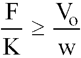

movable contact 22 does not bounce. - Thus, in designing a device of the type of Figure 1, one can, for example, take the movements of a similar existing device and simply alter solely the dimensions of the
movable contact member 22. The dimensions of this member should be such that it conforms to the equation (9) given above. - Figure 6 of the appended drawings shows, by way of example, a curve of the overall deflection X(t) of the movable contact/beam of a device for which the equation (7) or (more conservatively) the equation (9) given above is satisfied.
- In the graph of Figure 6, the static deflection xst has been considered to be constant and equal to the ratio between the force F and the elastic constant k of the movable contact/
beam 22. - Strictly, in a device of the type shown in Figure 1, the action of the
spring 24, which is further (though slightly) loaded after themovable contact 22 has struck the fixedcontacts 5a, also contributes to the definition of the static deflection xst. It should be noted, however, that the contribution to the static deflection due to this further loading of thespring 24 is extremely small if one takes account of the fact that it involves an extremely slow increase in the static deflection (as indicated, for example, by the broken line in Figure 6), whilst the oscillations of the dynamic component take place at a very high frequency. - In general, in order to comply with the conditions expressed by the equation (7) or the equation (9), the designer can alter the mass of the movable contact 22 (on which its basic vibration frequency f₁ and hence its angular frequency w=2πf₁ depends), the flexural elastic constant k of the movable contact, the elastic constant of the
spring 24, the preloading of the spring and the speed of the movable contact when it strikes the fixed contacts. This last parameter in turn depends on a series of factors such as the size of the control solenoid, the mass of the core 15, etc..
Claims (3)
- An electrical switch, particularly for controlling the supply of current to the electric starter motor of an internal combustion engine, including:- a support structure (2) carrying two fixed contacts (5),- a device (17) which carries a movable contact (22) and is movable relative to the support structure (2) between a rest position in which the movable contact (22) is separated from the fixed contacts (5) and an operating position in which the movable contact (22) is brought to bear against the fixed contacts (5), is deformed resiliently like a beam, and is subject to damped oscillations, and- control means (13, 15) for moving the movable device (17) between its rest position and its operating position,- in which the movable device (17; 22; 24) and/or the control means (13; 15) are formed in such a way that, in the operating position, the movable contact (22) oscillates after it has struck the fixed contacts (5) and assumes successive configurations in which its deformation or deflection (x) always keeps the same sign,characterised in that, after it has struck the fixed contacts (5), the movable contact (22) is subject to the combined effect of a static load (F) and damped vibrations which cause a resilient deflection (X(t)) of the movable contact (22) having a substantially constant static deflection component (xst) and a damped oscillating component (x(t)) which, during successive time intervals, alternately has a sign the same as and the opposite of that of the static component (xst), and- the dimensions of the device are such that the static component (xst) of the deflection of the movable contact (22) is greater than or at least equal to the maximum value (x(t₂)) assumed by the dynamic component (x(t)) whose sign is the opposite of that of the static component (xst).
- An electrical switch according to Claim 1, characterised in that the movable contact (22) comprises a single deformable member for bridging the fixed contacts (5).
- An electrical switch according to Claim 1, or Claim 2, characterised in that the dimensions of the movable contact (22) are such that its elastic constant (k) is less than or at least equal to w.F/Vo, in which "w" is the angular frequency corresponding to the basic frequency of the flexural vibration of the movable contact (w=2πF1), F is the static load and Vo is the speed of the movable contact when its resilient reaction equals the static load.
Applications Claiming Priority (2)
| Application Number | Priority Date | Filing Date | Title |
|---|---|---|---|
| IT67965A IT1241335B (en) | 1990-12-04 | 1990-12-04 | ELECTRIC SWITCH, IN PARTICULAR FOR THE CONTROL OF THE CURRENT SUPPLY TO THE ELECTRIC STARTING MOTOR OF AN INTERNAL COMBUSTION ENGINE |
| IT6796590 | 1990-12-04 |
Publications (2)
| Publication Number | Publication Date |
|---|---|
| EP0489697A1 EP0489697A1 (en) | 1992-06-10 |
| EP0489697B1 true EP0489697B1 (en) | 1996-05-22 |
Family
ID=11306792
Family Applications (1)
| Application Number | Title | Priority Date | Filing Date |
|---|---|---|---|
| EP91830518A Expired - Lifetime EP0489697B1 (en) | 1990-12-04 | 1991-11-26 | An electrical switch, particularly for controlling the supply of current to the electric starter motor of an internal combusion engine |
Country Status (10)
| Country | Link |
|---|---|
| US (1) | US5256992A (en) |
| EP (1) | EP0489697B1 (en) |
| JP (1) | JP3014193B2 (en) |
| BR (1) | BR9105246A (en) |
| DE (1) | DE69119720T2 (en) |
| ES (1) | ES2087276T3 (en) |
| IT (1) | IT1241335B (en) |
| PL (1) | PL169130B1 (en) |
| TR (1) | TR28679A (en) |
| YU (1) | YU48115B (en) |
Families Citing this family (12)
| Publication number | Priority date | Publication date | Assignee | Title |
|---|---|---|---|---|
| IT1257229B (en) * | 1992-06-10 | 1996-01-10 | Magneti Marelli Spa | ELECTROMAGNETIC DEVICE FOR THE CONTROL OF THE CURRENT SUPPLY TO THE ELECTRIC STARTING MOTOR OF AN INTERNAL COMBUSTION ENGINE. |
| FR2747836B1 (en) * | 1996-04-23 | 1998-05-22 | Valeo Equip Electr Moteur | STARTER CONTACTOR IN PARTICULAR FOR A MOTOR VEHICLE AND STARTER EQUIPPED WITH SUCH A CONTACTOR |
| JP4031889B2 (en) | 1999-07-29 | 2008-01-09 | 株式会社日立製作所 | Magnetic switch for starter |
| JP3770081B2 (en) | 2000-12-01 | 2006-04-26 | 株式会社デンソー | Magnetic switch for starter |
| JP2003208840A (en) * | 2002-01-10 | 2003-07-25 | Denso Corp | Electromagnetic switch for starter |
| US20060199457A1 (en) * | 2005-03-01 | 2006-09-07 | Kimberly-Clark Worldwide, Inc. | Cloth-like biaxial stretch nonwoven |
| JP2007087882A (en) * | 2005-09-26 | 2007-04-05 | Denso Corp | Electromagnetic switch |
| JP2016110843A (en) | 2014-12-05 | 2016-06-20 | オムロン株式会社 | Electromagnetic relay |
| JP6414453B2 (en) | 2014-12-05 | 2018-10-31 | オムロン株式会社 | Electromagnetic relay |
| JP6365684B2 (en) * | 2014-12-05 | 2018-08-01 | オムロン株式会社 | Electromagnetic relay |
| US10134551B2 (en) * | 2016-09-21 | 2018-11-20 | Astronics Advanced Electronic Systems Corp. | Galvanically isolated hybrid contactor |
| DE102017220503B3 (en) * | 2017-11-16 | 2019-01-17 | Te Connectivity Germany Gmbh | Double interrupting switch |
Family Cites Families (8)
| Publication number | Priority date | Publication date | Assignee | Title |
|---|---|---|---|---|
| DE1065919B (en) * | 1953-02-06 | |||
| DE1003318B (en) * | 1955-04-23 | 1957-02-28 | Maecker Elan Schaltelemente | Push switch |
| CH344491A (en) * | 1956-06-30 | 1960-02-15 | Siemens Ag | Bounce-free contact arrangement |
| DE1091194B (en) * | 1958-02-18 | 1960-10-20 | Licentia Gmbh | Resilient contact bridge e.g. for shooters |
| US3409851A (en) * | 1966-11-03 | 1968-11-05 | Ward Leonard Electric Co | Multipole electromagnetic contactor |
| US3472984A (en) * | 1967-08-01 | 1969-10-14 | Us Navy | Switch for high energy circuits utilizing contact bounce reduction |
| IT1195123B (en) * | 1986-08-07 | 1988-10-12 | Magneti Marelli Spa | ELECTROMAGNETIC DEVICE TO CONTROL THE POWER SUPPLY TO THE ELECTRIC STARTER OF AN INTERNAL COMBUSTION ENGINE |
| GB8800691D0 (en) * | 1988-01-13 | 1988-02-10 | Magneti Marelli Electrical | Electromagnetic actuator |
-
1990
- 1990-12-04 IT IT67965A patent/IT1241335B/en active IP Right Grant
-
1991
- 1991-10-29 US US07/784,542 patent/US5256992A/en not_active Expired - Lifetime
- 1991-11-22 PL PL91292501A patent/PL169130B1/en not_active IP Right Cessation
- 1991-11-26 EP EP91830518A patent/EP0489697B1/en not_active Expired - Lifetime
- 1991-11-26 DE DE69119720T patent/DE69119720T2/en not_active Expired - Fee Related
- 1991-11-26 ES ES91830518T patent/ES2087276T3/en not_active Expired - Lifetime
- 1991-11-27 YU YU186491A patent/YU48115B/en unknown
- 1991-11-28 JP JP3314334A patent/JP3014193B2/en not_active Expired - Fee Related
- 1991-11-29 BR BR919105246A patent/BR9105246A/en not_active IP Right Cessation
- 1991-12-03 TR TR01108/91A patent/TR28679A/en unknown
Also Published As
| Publication number | Publication date |
|---|---|
| JPH04301181A (en) | 1992-10-23 |
| US5256992A (en) | 1993-10-26 |
| EP0489697A1 (en) | 1992-06-10 |
| YU186491A (en) | 1994-06-24 |
| PL292501A1 (en) | 1992-10-19 |
| DE69119720T2 (en) | 1996-09-19 |
| IT9067965A1 (en) | 1992-06-05 |
| ES2087276T3 (en) | 1996-07-16 |
| IT9067965A0 (en) | 1990-12-04 |
| JP3014193B2 (en) | 2000-02-28 |
| TR28679A (en) | 1997-01-16 |
| PL169130B1 (en) | 1996-06-28 |
| YU48115B (en) | 1997-03-07 |
| IT1241335B (en) | 1994-01-10 |
| BR9105246A (en) | 1992-08-18 |
| DE69119720D1 (en) | 1996-06-27 |
Similar Documents
| Publication | Publication Date | Title |
|---|---|---|
| EP0489697A1 (en) | An electrical switch, particularly for controlling the supply of current to the electric starter motor of an internal combusion engine | |
| JPH0670429B2 (en) | Linear motion type actuator | |
| US2671836A (en) | Electromagnetic relay | |
| EP0573872B1 (en) | An electromagnetic device for controlling the supply of current to the electric starter motor of an internal combustion engine | |
| EP1713104B1 (en) | Electromagnetic relay | |
| US4625194A (en) | A.C. contactor | |
| KR0132663B1 (en) | Electronic switch | |
| JPH11291951A (en) | Body rigidity control device | |
| KR100365067B1 (en) | Method for seam welding overlapping sheet seam | |
| EP1876691A1 (en) | Magnetic drive actuator | |
| US5329265A (en) | Intermediate support relay for use particularly in motor vehicles | |
| CA1037531A (en) | Magnetically actuated switch for precise rapid cycle operation | |
| US5864268A (en) | Electromagnetic relay and method of adjustment of a response voltage thereof | |
| US5623239A (en) | Electrical contactor spring | |
| JP3195625B2 (en) | Electromagnetic relay | |
| US4081775A (en) | Apparatus for damping the bouncing or chatter of relay armatures in the releasing position | |
| JPH04241772A (en) | Starting device for internal-combustion engine and magnetically operatable starting motor using said device | |
| EP0171526A1 (en) | Backstop and damping apparatus for actuator | |
| US4844634A (en) | Printing head for an impact printer | |
| EP0250051B1 (en) | Needle printing head | |
| JP4385551B2 (en) | Contact distance adjustment method for electromagnetic relay | |
| US6870455B2 (en) | System and method for high accuracy activation of a mechanism via a solenoid | |
| JPS62204958A (en) | Printing head of wire dot printer | |
| EP0981138A2 (en) | Electromagnetic arrangements | |
| JPS63265652A (en) | impact dot head |
Legal Events
| Date | Code | Title | Description |
|---|---|---|---|
| PUAI | Public reference made under article 153(3) epc to a published international application that has entered the european phase |
Free format text: ORIGINAL CODE: 0009012 |
|
| AK | Designated contracting states |
Kind code of ref document: A1 Designated state(s): DE ES FR GB SE |
|
| 17P | Request for examination filed |
Effective date: 19920725 |
|
| 17Q | First examination report despatched |
Effective date: 19940907 |
|
| RAP1 | Party data changed (applicant data changed or rights of an application transferred) |
Owner name: INDUSTRIE MAGNETI MARELLI S.P.A. |
|
| GRAH | Despatch of communication of intention to grant a patent |
Free format text: ORIGINAL CODE: EPIDOS IGRA |
|
| GRAA | (expected) grant |
Free format text: ORIGINAL CODE: 0009210 |
|
| AK | Designated contracting states |
Kind code of ref document: B1 Designated state(s): DE ES FR GB SE |
|
| REG | Reference to a national code |
Ref country code: ES Ref legal event code: BA2A Ref document number: 2087276 Country of ref document: ES Kind code of ref document: T3 |
|
| REF | Corresponds to: |
Ref document number: 69119720 Country of ref document: DE Date of ref document: 19960627 |
|
| REG | Reference to a national code |
Ref country code: ES Ref legal event code: FG2A Ref document number: 2087276 Country of ref document: ES Kind code of ref document: T3 |
|
| ET | Fr: translation filed | ||
| PLBE | No opposition filed within time limit |
Free format text: ORIGINAL CODE: 0009261 |
|
| STAA | Information on the status of an ep patent application or granted ep patent |
Free format text: STATUS: NO OPPOSITION FILED WITHIN TIME LIMIT |
|
| 26N | No opposition filed | ||
| REG | Reference to a national code |
Ref country code: GB Ref legal event code: IF02 |
|
| PGFP | Annual fee paid to national office [announced via postgrant information from national office to epo] |
Ref country code: SE Payment date: 20050930 Year of fee payment: 15 |
|
| PGFP | Annual fee paid to national office [announced via postgrant information from national office to epo] |
Ref country code: ES Payment date: 20051006 Year of fee payment: 15 |
|
| PGFP | Annual fee paid to national office [announced via postgrant information from national office to epo] |
Ref country code: GB Payment date: 20051018 Year of fee payment: 15 |
|
| PGFP | Annual fee paid to national office [announced via postgrant information from national office to epo] |
Ref country code: DE Payment date: 20051026 Year of fee payment: 15 |
|
| PGFP | Annual fee paid to national office [announced via postgrant information from national office to epo] |
Ref country code: FR Payment date: 20051130 Year of fee payment: 15 |
|
| PG25 | Lapsed in a contracting state [announced via postgrant information from national office to epo] |
Ref country code: SE Free format text: LAPSE BECAUSE OF NON-PAYMENT OF DUE FEES Effective date: 20061127 |
|
| PG25 | Lapsed in a contracting state [announced via postgrant information from national office to epo] |
Ref country code: DE Free format text: LAPSE BECAUSE OF NON-PAYMENT OF DUE FEES Effective date: 20070601 |
|
| EUG | Se: european patent has lapsed | ||
| GBPC | Gb: european patent ceased through non-payment of renewal fee |
Effective date: 20061126 |
|
| REG | Reference to a national code |
Ref country code: FR Ref legal event code: ST Effective date: 20070731 |
|
| PG25 | Lapsed in a contracting state [announced via postgrant information from national office to epo] |
Ref country code: GB Free format text: LAPSE BECAUSE OF NON-PAYMENT OF DUE FEES Effective date: 20061126 |
|
| REG | Reference to a national code |
Ref country code: ES Ref legal event code: FD2A Effective date: 20061127 |
|
| PG25 | Lapsed in a contracting state [announced via postgrant information from national office to epo] |
Ref country code: ES Free format text: LAPSE BECAUSE OF NON-PAYMENT OF DUE FEES Effective date: 20061127 Ref country code: FR Free format text: LAPSE BECAUSE OF NON-PAYMENT OF DUE FEES Effective date: 20061130 |