EP0488875B1 - Perforating apparatus incorporating a shock absorber - Google Patents
Perforating apparatus incorporating a shock absorber Download PDFInfo
- Publication number
- EP0488875B1 EP0488875B1 EP91403183A EP91403183A EP0488875B1 EP 0488875 B1 EP0488875 B1 EP 0488875B1 EP 91403183 A EP91403183 A EP 91403183A EP 91403183 A EP91403183 A EP 91403183A EP 0488875 B1 EP0488875 B1 EP 0488875B1
- Authority
- EP
- European Patent Office
- Prior art keywords
- shock
- energy
- shock absorber
- perforating gun
- perforating
- Prior art date
- Legal status (The legal status is an assumption and is not a legal conclusion. Google has not performed a legal analysis and makes no representation as to the accuracy of the status listed.)
- Expired - Lifetime
Links
Images



Classifications
-
- E—FIXED CONSTRUCTIONS
- E21—EARTH OR ROCK DRILLING; MINING
- E21B—EARTH OR ROCK DRILLING; OBTAINING OIL, GAS, WATER, SOLUBLE OR MELTABLE MATERIALS OR A SLURRY OF MINERALS FROM WELLS
- E21B17/00—Drilling rods or pipes; Flexible drill strings; Kellies; Drill collars; Sucker rods; Cables; Casings; Tubings
- E21B17/02—Couplings; joints
- E21B17/04—Couplings; joints between rod or the like and bit or between rod and rod or the like
- E21B17/07—Telescoping joints for varying drill string lengths; Shock absorbers
Definitions
- the present invention relates to perforating apparatus incorporating a shock absorber, and more particularly, provides a shock absorber which is incorporated in a perforating gun string and which includes a collapsible energy absorbing element adapted to permanently deform when absorbing shock.
- Perforating guns are adapted to be disposed in a wellbore for perforating a formation. Well fluids flow from the perforated formation.
- a shock is received in the tubing string above the perforating gun.
- a shock absorber is usually incorporated in the tubing string above the perforating gun for absorbing the shock.
- the shock absorber usually includes a spring which stores mechanical energy by compression in response to the shock and releases the mechanical energy by expansion following compression over a longer period of time such that the force exerted is reduced.
- US-A-4 905 759 discloses a collapsible perforating gun assembly, comprising a spacer mandrel having two telescopically collapsible parts which are initially prevented from relative axial movement, but which are freed to telescope together during firing of the perforating gun.
- the purpose of this arrangement is to reduce the length of the assembly after firing, and no mechanism for absorbing the shock resulting from firing is disclosed.
- US-A-3 856 335 discloses a rolling diaphragm slip joint for inclusion in a casing string leading to an underground nuclear test site. The shock caused by the explosion is partly absorbed by plastic deformation of the rolling diaphragm.
- perforating apparatus for use at the lower end of a tubing string in a well bore, the apparatus comprising:
- a shock absorber adapted to be connected to a well apparatus for absorbing shock, the shock absorber including an energy absorbing element, comprising the steps of:
- Perforating guns are utilized in well logging for perforating a formation traversed by a borehole, well fluids being produced from the perforated formation.
- the perforating guns contain shape charges; when the shape charges detonate, the formation is perforated; however, a shock is generated from the gun, the shock propagating up the gun string.
- shock absorbers are usually incorporated within the tubing string above the perforating gun. All such shock absorbers to date absorb mechanical energy and subsequently release the mechanical energy in the form of kinetic energy. It has been important to carefully analyze the release of mechanical energy since an abrupt release of the mechanical energy may produce still another shock.
- Typical prior art shock absorbers store mechanical energy during absorption of a shock and subsequently release the mechanical energy in the form of kinetic energy.
- the mechanical energy is stored during compression of the spring and is released in the form of kinetic energy during expansion of the spring.
- Shock severity may be reduced by storage of the input energy and its release in a "smoother" form over a longer period of time.
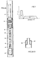
- the energy input "IN” to a shock absorber system is shown by the first energy pulse
- the energy released “OUT” from the shock absorber system is shown by the second energy pulse.
- the second energy pulse "OUT” illustrates a relatively flat amplitude pulse, the amplitude of the second pulse being smaller than the amplitude of the first pulse thereby indicating a release of the mechanical energy in a smoother form over a longer period of time.
- shock absorbers of the prior art released their stored mechanical energy in the form of kinetic energy. Improvements to the shock absorbers of the prior art have primarily involved generating a smoother release of the stored mechanical energy in the form of kinetic energy.
- the shock absorber of the perforating apparatus of the present invention ultilizes a different principle of operation; that is, it is a "single event" shock absorber, one which receives mechanical energy during energy absorption but does not subsequently release the stored mechanical energy in the form of kinetic energy; instead, it releases the stored mechanical energy in the form of heat. This permits the shock absorber to be incorporated within the perforating gun string as well as within the tubing string above the perforating gun.
- a shock absorber in perforating apparatus in accordance with the present invention is disposed below a firing head of a perforating gun and within the perforating gun string.
- a perforating gun 30 is connected to one end of a tubing string 32 in a borehole and an isolation packer 34 is disposed within the tubing string 32 above the perforating gun 30; when the packer 34 is set, an interval between the tubing string and a wall of the borehole above the packer is isolated from an interval between the tubing and the wall of the borehole below the packer.
- a gun release sub 50, a debris circulating sub 52, a drop bar firing head assembly 36, and a "single event" shock absorber assembly 38 are disposed between the perforating gun 30 and the isolation packer 34 on the tubing 32.
- the firing head assembly 36 is disposed above the perforating gun 30, and the "single event" shock absorber assembly is disposed below the firing head 36 and within the perforating gun 30 (and not within the tubing string above the firing head).
- the shock absorber assembly 38 contains an energy absorbing element (not shown) disposed within a space 38a of the shock absorber 38, the energy absorbing element storing mechanical energy during shock absorption, and subsequently releasing the stored energy in the form of heat (not kinetic energy).
- the shock absorber 38 is not located above the firing head 36 within the tubing string 32, fullbore access to the firing head 36 is available to a user at the well surface.
- Figure 2b shows perforating apparatus in accordance with the present invention, in which a shock absorber is disposed above a firing head of a perforating gun and within the tubing string.
- a perforating gun 30 is connected to one end of a tubing string 32 in a borehole and an isolation packer 34 is disposed within the tubing string 32 above the perforating gun 30; when the packer 34 is set, an interval between the tubing string and a wall of the borehole above the packer is isolated from an interval between the tubing and the wall of the borehole below the packer.
- a "single event" shock absorber 38, a gun release sub 50, a debris circulating sub 52, and a drop bar firing head assembly 36 are disposed between the packer 34 and the perforating gun 30 on the tubing 32.
- the "single event" shock absorber assembly 38 is disposed above the firing head 36 of perforating gun 30 and between the gun release sub 50 and the packer 34 within the tubing 32. Since the shock absorber 38 is a "single event” type, it can be equally effective, relative to the shock absorber of figure 2a, in absorbing shock when disposed above the firing head 36 within the tubing string 32.
- the shock absorber of figure 2b also includes a space 38a in which a "single event” energy absorbing element is disposed.
- the term “single event” connotes the absorption of mechanical energy resultant from a shock produced during detonation of the perforating gun, but not the release of the stored mechanical energy in the form of kinetic energy.
- the energy absorbing element comprises a hollow damping coil 18.
- the hollow coil 18 When a compressive force is applied to both of the ends of the hollow coil 18, the hollow coil 18 will permanently deform. The coil 18 will not expand following compression; therefore, the stored mechanical energy is not subsequently released in the form of kinetic energy; rather, the stored energy will be released in the form of heat.
- shock absorber 38 of figure 2a designed to be fit below the firing head assembly 36 and within the perforating gun 30, is illustrated.
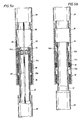
- one embodiment of the shock absorber 38 of figure 2a is shown, and comprises an outer housing 10 having one end including a first inwardly disposed transverse member 10a, an inner housing 12 which includes a second transverse member 12a transversely disposed with respect to the inner housing 12 and having a surface in contact with an inner surface of the outer housing 10, and a joining member 14 which joins the outer housing 10 to the inner housing 12, the joining member 14 including an inner piece 14a forming an integral part of the inner housing 12, an outer piece 14b having one end integrally joined to the inner piece 14a, and a third transverse member 14c integrally joined to the other end of the other piece 14b, the third transerse member 14c contacting an inner surface of the outer housing 10.
- a first space is defined between the inner housing 12 and the outer housing 10 by the first inwardly disposed transverse member 10a of the outer housing 10 and the second transverse member 12a of the inner housing 12; a first energy absorbing element 16, otherwise termed a damping coil 16, is disposed within the first space.
- a second space is defined between the inner housing 12 and the outer housing 10 by the second transverse member 12a of the inner housing 12 and the third transverse member 14c of the joining member 14; a second energy absorbing element, or damping coil, 18 is disposed within the second space.
- the first and second damping coils 16 and 18 may each be made of aluminum or stainless steel. Each damping coil 16 and 18 has a hollow interior such that the damping coil will collapse and permanently deform when a compressive force of a predetermined magnitude is applied to the coil.
- a break up shape charge 20 is disposed within the inner housing 12, and a detonating cord 22 passes through the center of the break up charge 20.
- the break up shape charge 20 detonates when a detonation wave propagates along the detonating cord 22 and through the shape charge 20, the shape charge 20 severing the inner piece 14a of the joining member 14 into two parts thereby separating the inner housing 12 from the outer housing 10.
- the shock absorber 38 Before the inner housing 12 is separated from the outer housing 10 by the shape charge 20, the shock absorber 38 is as strong as the tubing string 32; however, after the inner housing 12 is separated from the outer housing 10 by the break up shape charge 20, the shock absorber 38 is as flexible as any other shock absorber and therefore functions as a shock absorber.
- shock absorber 38 of figures 2a, 2a(1) and figure 4 will be set forth in the following paragraphs with reference to figures 4, 5a and 5b of the drawings.
- the shock absorber is incorporated below firing head 36 within a perforating gun string.
- the perforating gun 30 includes a plurality of shape charges.
- the shock absorber is shown before detonation of the shape charges disposed within the perforating gun; in figure 5a, the shock absorber is shown during detonation of the charges; and, in figure 5b, the shock absorber is shown after detonation of the perforating gun charges.
- a detonation wave propagates along detonating cord 22 indicating that the plurality of shape charges in the perforating gun are either detonating or are about to detonate.
- the charge 20 cuts the joining member 14 into two pieces (e.g., severs the inner piece 14a into two pieces) thereby separating the inner housing 12 from the outer housing 10.
- the breakup charge 20 is shown cutting the joining member 14 into two pieces, but the shock from the detonation of the perforation gun has not yet been received.
- shock absorber 38 of figure 2b designed to be fit above the firing head assembly 36 within the tubing string 32, is illustrated.
- shock absorber 38 of figures 4, 5a, 5b was designed to fit below the firing head 36 and within the perforating gun 30, the shock absorber 38 of figure 6 is designed to fit within the tubing string 32 above the firing head 36.
- the only other significant difference between the shock absorber 38 of figures 4, 5a and 5b and the shock absorber 38 of figure 6 is the specific structure of the energy absorbing element adapted to fit within space 38a of figure 2a(1).
- the damping coil 18 of figure 4 was the energy absorbing element used in connection with the shock absorber of figures 4, 5a and 5b
- a corrugated honeycomb 40 is the energy absorbing element used in connection with the shock absorber of figure 6.
- Figure 6a illustrates the cross-sectional structure of the honeycomb 40 of figure 6, figure 6a being a cross section of the shock absorber 38 of figure 6, taken along section lines 6a-6a of figure 6.
- there are a plurality of layers of the corrugated structure 40 in figure 6a each corrugated layer being disposed on top of its adjacent corrugated layer, the plurality of corrugated layers 40 collectively comprising the honeycomb energy absorbing element adapted to fit within space 38a of the shock absorber 38 of figure 2b.
- the honeycomb 40 energy absorbing element absorbs mechanical energy and permanently deforms, the deformation being the same as that illustrated in figure 5b. Mechanical energy is absorbed and stored during the deformation of honeycomb 40; however, the stored energy is released in the form of heat, and not in the form of kinetic energy.
- FIG 7 a plot of force vs. displacement for various types of energy absorbing elements disposed in a shock absorber is illustrated, the energy absorbed by a particular energy absorbing element being equal to the area under its curve.
- a prior art rubber elastomer energy absorbing element is illustrated as having the worst energy absorption, since the area under its curve is the least as compared to a spring element, a damping coil element and a honeycomb element.
- the honeycomb energy absorbing element 40 possesses the best energy absorption since it has the largest area under its curve and exhibits the lowest reaction force for a given energy absorption.
- the damping coil energy absorbing element 18 possesses the next best energy absorption.
Landscapes
- Engineering & Computer Science (AREA)
- Life Sciences & Earth Sciences (AREA)
- Geology (AREA)
- Mining & Mineral Resources (AREA)
- Mechanical Engineering (AREA)
- Physics & Mathematics (AREA)
- Environmental & Geological Engineering (AREA)
- Fluid Mechanics (AREA)
- General Life Sciences & Earth Sciences (AREA)
- Geochemistry & Mineralogy (AREA)
- Vibration Dampers (AREA)
Description
- The present invention relates to perforating apparatus incorporating a shock absorber, and more particularly, provides a shock absorber which is incorporated in a perforating gun string and which includes a collapsible energy absorbing element adapted to permanently deform when absorbing shock.
- Perforating guns are adapted to be disposed in a wellbore for perforating a formation. Well fluids flow from the perforated formation. When the perforating gun fires, a shock is received in the tubing string above the perforating gun. A shock absorber is usually incorporated in the tubing string above the perforating gun for absorbing the shock. The shock absorber usually includes a spring which stores mechanical energy by compression in response to the shock and releases the mechanical energy by expansion following compression over a longer period of time such that the force exerted is reduced. Although this configuration absorbs mechanical energy associated with the shock, attempts to improve this shock absorber have focussed on achieving a smoother release of the mechanical energy from the spring coil shock absorber system following storage of the mechanical energy.
- However, the problem associated with the release of the mechanical energy could be eliminated entirely if the absorbing element in the shock absosrber did not expand following compression but, instead, released the stored energy in a different form, such as heat.
- US-A-4 905 759 discloses a collapsible perforating gun assembly, comprising a spacer mandrel having two telescopically collapsible parts which are initially prevented from relative axial movement, but which are freed to telescope together during firing of the perforating gun. The purpose of this arrangement is to reduce the length of the assembly after firing, and no mechanism for absorbing the shock resulting from firing is disclosed.
- US-A-3 856 335 discloses a rolling diaphragm slip joint for inclusion in a casing string leading to an underground nuclear test site. The shock caused by the explosion is partly absorbed by plastic deformation of the rolling diaphragm.
- It is an object of the present invention to provide perforating apparatus having improved shock absorbing characteristics.
- According to one aspect of the present invention, there is provided perforating apparatus for use at the lower end of a tubing string in a well bore, the apparatus comprising:
- a perforating gun for perforating the formation around the well bore;
- a detonating cord for firing said perforating gun; and
- shock absorbing means between the perforating gun and the tubing string for absorbing the shock produced by the firing of said perforating gun;
- inner and outer housing members which are initially rigidly connected together;
- means responsive to the detonation wave which propagates along the detonating cord during the firing of the perforating gun to break the connection between the housing members and thereby render them relatively axially movable; and
- collapsible energy absorbing means arranged to be permanently deformed by the relative axial movement of the housing members, whereby to absorb said shock.
- According to another aspect of the present invention, there is provided a method practised by a shock absorber adapted to be connected to a well apparatus for absorbing shock, the shock absorber including an energy absorbing element, comprising the steps of:
- breaking a connection between an outer housing and an inner housing of said shock absorber immediately prior to said shock, the inner housing being released from the outer housing when the connection is broken;
- receiving said shock in said energy absorbing element of said shock absorber;
- storing mechanical energy associated with said shock in said energy absorbing element; and
- subsequently releasing the stored energy in the form of heat and not in the form of kinetic energy.
- Further scope of applicability of the present invention will become apparent from the detailed description presented hereinafter. It should be understood, however, that the detailed description and the specific examples, while representing a preferred embodiment of the present invention, are given by way of illustration only, since various changes and modifications within the scope of the invention will become obvious to one skilled in the art from a reading of the following detailed description.
- A full understanding of the present invention will be obtained from the detailed description of the preferred embodiment presented hereinbelow, and the accompanying drawings, which are given by way of illustration only and are not intended to be limitative of the present invention, and wherein:
- figure 1 illustrates an optimum theory associated with shock absorption in a perforating gun string;
- figure 2a illustrates a perforating gun including a firing head disposed on an end of a tubing string, and an energy absorbing element shock absorber disposed below the firing head within the perforating gun;
- figure 2a(1) illustrates the shock absorber of figure 2a in greater detail;
- figure 2b illustrates a perforating gun including a firing head disposed on an end of a tubing string, and an energy absorbing element shock absorber disposed above the firing head of the perforating gun;
- figure 3 illustrates an energy absorbing element adapted to be disposed within the shock absorber;
- figure 4 illustrates perforating apparatus in accordance with the present invention, comprising a novel shock absorber adapted to be incorporated below a perforating gun firing head and within a perforating gun string, the shock absorber including a damping coil mechanical energy absorbing element;
- figures 5a and 5b illustrate the shock absorber of figure 4 during and after detonation of the perforating gun;
- figure 6 illustrates perforating apparatus in accordance with another embodiment of the present invention and comprising a further novel shock absorber adapted to be incorporated above a perforating gun firing head and within a tubing string, the shock absorber including a honeycomb mechanical energy absorbing element;
- figure 6a is a cross-section of the shock absorber of figure 6, taken along
section lines 6a-6a of figure 6; and - figure 7 illustrates a plurality of graphs of force vs displacement for various types of energy absorbing shock absorbers.
- Perforating guns are utilized in well logging for perforating a formation traversed by a borehole, well fluids being produced from the perforated formation. The perforating guns contain shape charges; when the shape charges detonate, the formation is perforated; however, a shock is generated from the gun, the shock propagating up the gun string. In order to reduce the severity of the shock, shock absorbers are usually incorporated within the tubing string above the perforating gun. All such shock absorbers to date absorb mechanical energy and subsequently release the mechanical energy in the form of kinetic energy. It has been important to carefully analyze the release of mechanical energy since an abrupt release of the mechanical energy may produce still another shock.
- Typical prior art shock absorbers store mechanical energy during absorption of a shock and subsequently release the mechanical energy in the form of kinetic energy. For example, in a standard spring shock absorber, the mechanical energy is stored during compression of the spring and is released in the form of kinetic energy during expansion of the spring. Shock severity may be reduced by storage of the input energy and its release in a "smoother" form over a longer period of time.
- For example, referring to figure 1, the energy input "IN" to a shock absorber system is shown by the first energy pulse, and the energy released "OUT" from the shock absorber system is shown by the second energy pulse. Note that the second energy pulse "OUT" illustrates a relatively flat amplitude pulse, the amplitude of the second pulse being smaller than the amplitude of the first pulse thereby indicating a release of the mechanical energy in a smoother form over a longer period of time.
- Shock absorbers of the prior art released their stored mechanical energy in the form of kinetic energy. Improvements to the shock absorbers of the prior art have primarily involved generating a smoother release of the stored mechanical energy in the form of kinetic energy. However, the shock absorber of the perforating apparatus of the present invention ultilizes a different principle of operation; that is, it is a "single event" shock absorber, one which receives mechanical energy during energy absorption but does not subsequently release the stored mechanical energy in the form of kinetic energy; instead, it releases the stored mechanical energy in the form of heat. This permits the shock absorber to be incorporated within the perforating gun string as well as within the tubing string above the perforating gun.
- Referring to figures 2a and 2a(1), a shock absorber in perforating apparatus in accordance with the present invention is disposed below a firing head of a perforating gun and within the perforating gun string.
- In figure 2a, a
perforating gun 30 is connected to one end of atubing string 32 in a borehole and anisolation packer 34 is disposed within thetubing string 32 above theperforating gun 30; when thepacker 34 is set, an interval between the tubing string and a wall of the borehole above the packer is isolated from an interval between the tubing and the wall of the borehole below the packer. Agun release sub 50, adebris circulating sub 52, a drop barfiring head assembly 36, and a "single event"shock absorber assembly 38 are disposed between the perforatinggun 30 and theisolation packer 34 on thetubing 32. Thefiring head assembly 36 is disposed above theperforating gun 30, and the "single event" shock absorber assembly is disposed below thefiring head 36 and within the perforating gun 30 (and not within the tubing string above the firing head). In figure 2a(a), theshock absorber assembly 38 contains an energy absorbing element (not shown) disposed within aspace 38a of theshock absorber 38, the energy absorbing element storing mechanical energy during shock absorption, and subsequently releasing the stored energy in the form of heat (not kinetic energy). As a result, since theshock absorber 38 is not located above thefiring head 36 within thetubing string 32, fullbore access to thefiring head 36 is available to a user at the well surface. - Figure 2b shows perforating apparatus in accordance with the present invention, in which a shock absorber is disposed above a firing head of a perforating gun and within the tubing string.
- In figure 2b, a
perforating gun 30 is connected to one end of atubing string 32 in a borehole and anisolation packer 34 is disposed within thetubing string 32 above theperforating gun 30; when thepacker 34 is set, an interval between the tubing string and a wall of the borehole above the packer is isolated from an interval between the tubing and the wall of the borehole below the packer. A "single event"shock absorber 38, agun release sub 50, adebris circulating sub 52, and a drop bar firinghead assembly 36 are disposed between thepacker 34 and the perforatinggun 30 on thetubing 32. The "single event"shock absorber assembly 38 is disposed above the firinghead 36 of perforatinggun 30 and between thegun release sub 50 and thepacker 34 within thetubing 32. Since theshock absorber 38 is a "single event" type, it can be equally effective, relative to the shock absorber of figure 2a, in absorbing shock when disposed above the firinghead 36 within thetubing string 32. The shock absorber of figure 2b also includes aspace 38a in which a "single event" energy absorbing element is disposed. The term "single event" connotes the absorption of mechanical energy resultant from a shock produced during detonation of the perforating gun, but not the release of the stored mechanical energy in the form of kinetic energy. - Referring to figure 3, one embodiment of a "single event" energy absorbing element, adapted to be disposed within
space 38a of figure 2a(1), is illustrated. In figure 3, the energy absorbing element comprises a hollow dampingcoil 18. When a compressive force is applied to both of the ends of thehollow coil 18, thehollow coil 18 will permanently deform. Thecoil 18 will not expand following compression; therefore, the stored mechanical energy is not subsequently released in the form of kinetic energy; rather, the stored energy will be released in the form of heat. - Referring to figure 4, a detailed construction of the
shock absorber 38 of figure 2a, designed to be fit below the firinghead assembly 36 and within the perforatinggun 30, is illustrated. - In figure 4, one embodiment of the
shock absorber 38 of figure 2a is shown, and comprises anouter housing 10 having one end including a first inwardly disposedtransverse member 10a, aninner housing 12 which includes a secondtransverse member 12a transversely disposed with respect to theinner housing 12 and having a surface in contact with an inner surface of theouter housing 10, and a joiningmember 14 which joins theouter housing 10 to theinner housing 12, the joiningmember 14 including an inner piece 14a forming an integral part of theinner housing 12, anouter piece 14b having one end integrally joined to the inner piece 14a, and a third transverse member 14c integrally joined to the other end of theother piece 14b, the third transerse member 14c contacting an inner surface of theouter housing 10. A first space is defined between theinner housing 12 and theouter housing 10 by the first inwardly disposedtransverse member 10a of theouter housing 10 and the secondtransverse member 12a of theinner housing 12; a firstenergy absorbing element 16, otherwise termed a dampingcoil 16, is disposed within the first space. A second space is defined between theinner housing 12 and theouter housing 10 by the secondtransverse member 12a of theinner housing 12 and the third transverse member 14c of the joiningmember 14; a second energy absorbing element, or damping coil, 18 is disposed within the second space. The first and second damping coils 16 and 18 may each be made of aluminum or stainless steel. Each dampingcoil - A break up
shape charge 20 is disposed within theinner housing 12, and a detonatingcord 22 passes through the center of the break upcharge 20. As will be more apparent with reference to figures 5a-5b, the break upshape charge 20 detonates when a detonation wave propagates along the detonatingcord 22 and through theshape charge 20, theshape charge 20 severing the inner piece 14a of the joiningmember 14 into two parts thereby separating theinner housing 12 from theouter housing 10. Before theinner housing 12 is separated from theouter housing 10 by theshape charge 20, theshock absorber 38 is as strong as thetubing string 32; however, after theinner housing 12 is separated from theouter housing 10 by the break upshape charge 20, theshock absorber 38 is as flexible as any other shock absorber and therefore functions as a shock absorber. - A functional description of the
shock absorber 38 of figures 2a, 2a(1) and figure 4 will be set forth in the following paragraphs with reference to figures 4, 5a and 5b of the drawings. - In figures 4, 5a, 5b, the shock absorber is incorporated below firing
head 36 within a perforating gun string. The perforatinggun 30 includes a plurality of shape charges. In figure 4, the shock absorber is shown before detonation of the shape charges disposed within the perforating gun; in figure 5a, the shock absorber is shown during detonation of the charges; and, in figure 5b, the shock absorber is shown after detonation of the perforating gun charges. - In figure 4, the shock absorber is shown undisturbed, since a detonation wave has not yet propagated along detonating
cord 22, and none of the shape charges of the perforating gun have detonated. - In figure 5a, a detonation wave propagates along detonating
cord 22 indicating that the plurality of shape charges in the perforating gun are either detonating or are about to detonate. when the detonation wave passes through the center of the break upcharge 20 in figure 5a, thecharge 20 cuts the joiningmember 14 into two pieces (e.g., severs the inner piece 14a into two pieces) thereby separating theinner housing 12 from theouter housing 10. In figure 5a, thebreakup charge 20 is shown cutting the joiningmember 14 into two pieces, but the shock from the detonation of the perforation gun has not yet been received. - In figure 5b, the joining
member 14 has been cut, the inner piece 14a being shown as separated from theouter piece 14b of the joiningmember 14. As a result,inner housing 12 is separated fromouter housing 10. In addition, a shock from the detonated perforating gun has been received, the shock causing theinner housing 12 to move upwardly in figure 5b relative to theouter housing 10. The secondtransverse member 12a of theinner housing 12 moves toward the third transverse member 14c of the joiningmember 14 thereby crushing the second dampingcoil 18 disposed within the second space. As a result, the second dampingcoil 18 has collapsed and is now permanently deformed. Although mechanical energy was stored in the dampingcoil 18 during compression, since the dampingcoil 18 has collapsed and is permanently deformed, no expansion of thecoil 18 will occur; therefore, the mechanical energy is not released in the form of kinetic energy; rather, it is released in the form of heat. - Referring to figures 6 and 6a, a detailed construction of the
shock absorber 38 of figure 2b, designed to be fit above the firinghead assembly 36 within thetubing string 32, is illustrated. - While the
shock absorber 38 of figures 4, 5a, 5b was designed to fit below the firinghead 36 and within the perforatinggun 30, theshock absorber 38 of figure 6 is designed to fit within thetubing string 32 above the firinghead 36. The only other significant difference between theshock absorber 38 of figures 4, 5a and 5b and theshock absorber 38 of figure 6 is the specific structure of the energy absorbing element adapted to fit withinspace 38a of figure 2a(1). Whereas the dampingcoil 18 of figure 4 was the energy absorbing element used in connection with the shock absorber of figures 4, 5a and 5b, acorrugated honeycomb 40 is the energy absorbing element used in connection with the shock absorber of figure 6. - Figure 6a illustrates the cross-sectional structure of the
honeycomb 40 of figure 6, figure 6a being a cross section of theshock absorber 38 of figure 6, taken alongsection lines 6a-6a of figure 6. In figure 6a, note the "corrugated" structure of the honeycombenergy absorbing element 40 of figure 6. In fact, there are a plurality of layers of thecorrugated structure 40 in figure 6a, each corrugated layer being disposed on top of its adjacent corrugated layer, the plurality ofcorrugated layers 40 collectively comprising the honeycomb energy absorbing element adapted to fit withinspace 38a of theshock absorber 38 of figure 2b. When the perforating gun charges detonate, thehoneycomb 40 energy absorbing element absorbs mechanical energy and permanently deforms, the deformation being the same as that illustrated in figure 5b. Mechanical energy is absorbed and stored during the deformation ofhoneycomb 40; however, the stored energy is released in the form of heat, and not in the form of kinetic energy. - Referring to figure 7, a plot of force vs. displacement for various types of energy absorbing elements disposed in a shock absorber is illustrated, the energy absorbed by a particular energy absorbing element being equal to the area under its curve. In figure 7, a prior art rubber elastomer energy absorbing element is illustrated as having the worst energy absorption, since the area under its curve is the least as compared to a spring element, a damping coil element and a honeycomb element. The honeycomb
energy absorbing element 40 possesses the best energy absorption since it has the largest area under its curve and exhibits the lowest reaction force for a given energy absorption. The damping coilenergy absorbing element 18 possesses the next best energy absorption.
Claims (6)
- Perforating apparatus for use at the lower end of a tubing string in a well bore, the apparatus comprising:a perforating gun (30) for perforating the formation around the well bore;a detonating cord (22) for firing said perforating gun (30); andshock absorbing means (38) between the perforating gun (30) and the tubing string (32) for absorbing the shock produced by the firing of said perforating gun;characterised in that the shock absorbing means (38) comprises:inner and outer housing members (12, 10) which are initially rigidly connected together;means (20) responsive to the detonation wave which propagates along the detonating cord (22) during the firing of the perforating gun (30) to break the connection between the housing members (12, 10) and thereby render them relatively axially movable; andcollapsible energy absorbing means (16, 18 or 40) arranged to be permanently deformed by the relative axial movement of the housing members, thereby absorbing said shock and releasing energy in the form of heat rather than in the form of kinetic energy.
- Apparatus as claimed in claim 1, wherein the collapsible energy absorbing means comprises a coiled tube (16 or 18).
- Apparatus as claimed in claim 1, wherein the collapsible energy absorbing means comprises a honeycomb (40).
- Apparatus as claimed in any preceding claim, wherein respective collapsible energy absorbing means (16 or 18, or 40) is provided for both possible directions of relative movement between the inner and outer housing members (12, 10).
- Apparatus as claimed in any preceding claim, wherein the detonation wave responsive means comprises a shaped charge (20).
- A method practised by a shock absorber (38) adapted to be connected to a well apparatus for absorbing shock, the shock absorber including an energy absorbing element (16, 18 or 40), comprising the steps of:breaking a connection between an outer housing (10) and an inner housing (12) of said shock absorber (38) immediately prior to said shock, the inner housing being released from the outer housing when the connection is broken;receiving said shock in said energy absorbing element (16, 18 or 40) of said shock absorber (38);storing mechanical energy associated with said shock in said energy absorbing element (16, 18 or 40); andsubsequently releasing the stored energy in the form of heat and not in the form of kinetic energy.
Applications Claiming Priority (2)
| Application Number | Priority Date | Filing Date | Title |
|---|---|---|---|
| US07/618,422 US5131470A (en) | 1990-11-27 | 1990-11-27 | Shock energy absorber including collapsible energy absorbing element and break up of tensile connection |
| US618422 | 1990-11-27 |
Publications (3)
| Publication Number | Publication Date |
|---|---|
| EP0488875A2 EP0488875A2 (en) | 1992-06-03 |
| EP0488875A3 EP0488875A3 (en) | 1993-03-31 |
| EP0488875B1 true EP0488875B1 (en) | 1997-01-08 |
Family
ID=24477605
Family Applications (1)
| Application Number | Title | Priority Date | Filing Date |
|---|---|---|---|
| EP91403183A Expired - Lifetime EP0488875B1 (en) | 1990-11-27 | 1991-11-26 | Perforating apparatus incorporating a shock absorber |
Country Status (2)
| Country | Link |
|---|---|
| US (1) | US5131470A (en) |
| EP (1) | EP0488875B1 (en) |
Families Citing this family (37)
| Publication number | Priority date | Publication date | Assignee | Title |
|---|---|---|---|---|
| US5509481A (en) * | 1992-03-26 | 1996-04-23 | Schlumberger Technology Corporation | Method of perforating including an automatic release apparatus suspending by wireline or coiled tubing in a wellbore for perforating a long length interval of the wellbore in a single run using a gun string longer than a wellhead lubricator |
| US5366013A (en) * | 1992-03-26 | 1994-11-22 | Schlumberger Technology Corporation | Shock absorber for use in a wellbore including a frangible breakup element preventing shock absorption before shattering allowing shock absorption after shattering |
| DE9416982U1 (en) * | 1994-10-21 | 1994-12-01 | Bauer Spezialtiefbau Gmbh, 86529 Schrobenhausen | Damping element for a telescopic boring bar |
| US5954133A (en) * | 1996-09-12 | 1999-09-21 | Halliburton Energy Services, Inc. | Methods of completing wells utilizing wellbore equipment positioning apparatus |
| US6109355A (en) * | 1998-07-23 | 2000-08-29 | Pes Limited | Tool string shock absorber |
| WO2001007860A2 (en) * | 1999-07-22 | 2001-02-01 | Schlumberger Technology Corporation | Components and methods for use with explosives |
| AU2200001A (en) * | 1999-12-21 | 2001-07-03 | Keyguard Limited | Energy absorber |
| GB2370089C (en) * | 2000-05-18 | 2002-08-21 | Keyguard Ltd | Energy absorber |
| US7455104B2 (en) * | 2000-06-01 | 2008-11-25 | Schlumberger Technology Corporation | Expandable elements |
| US7121340B2 (en) * | 2004-04-23 | 2006-10-17 | Schlumberger Technology Corporation | Method and apparatus for reducing pressure in a perforating gun |
| US20050269083A1 (en) * | 2004-05-03 | 2005-12-08 | Halliburton Energy Services, Inc. | Onboard navigation system for downhole tool |
| US20060118297A1 (en) * | 2004-12-07 | 2006-06-08 | Schlumberger Technology Corporation | Downhole tool shock absorber |
| US7721820B2 (en) * | 2008-03-07 | 2010-05-25 | Baker Hughes Incorporated | Buffer for explosive device |
| EP2313597A2 (en) * | 2008-05-20 | 2011-04-27 | John P. Rodgers | System and method for providing a downhole mechanical energy absorber |
| NO329955B1 (en) * | 2008-10-30 | 2011-01-31 | Nat Oilwell Varco Norway As | Device for mouse hole muffler |
| US8136608B2 (en) | 2008-12-16 | 2012-03-20 | Schlumberger Technology Corporation | Mitigating perforating gun shock |
| WO2012061506A2 (en) | 2010-11-02 | 2012-05-10 | National Oilwell Varco Norway As | A drilling system and a device for assembling and disassembling pipe stands |
| US8397814B2 (en) * | 2010-12-17 | 2013-03-19 | Halliburton Energy Serivces, Inc. | Perforating string with bending shock de-coupler |
| US8985200B2 (en) | 2010-12-17 | 2015-03-24 | Halliburton Energy Services, Inc. | Sensing shock during well perforating |
| MX2013006899A (en) | 2010-12-17 | 2013-07-17 | Halliburton Energy Serv Inc | Well perforating with determination of well characteristics. |
| WO2012148429A1 (en) | 2011-04-29 | 2012-11-01 | Halliburton Energy Services, Inc. | Shock load mitigation in a downhole perforation tool assembly |
| US8397800B2 (en) * | 2010-12-17 | 2013-03-19 | Halliburton Energy Services, Inc. | Perforating string with longitudinal shock de-coupler |
| US8393393B2 (en) | 2010-12-17 | 2013-03-12 | Halliburton Energy Services, Inc. | Coupler compliance tuning for mitigating shock produced by well perforating |
| AU2011363051B2 (en) * | 2011-03-22 | 2015-09-24 | Halliburton Energy Services, Inc. | Well tool assemblies with quick connectors and shock mitigating capabilities |
| US20120241169A1 (en) | 2011-03-22 | 2012-09-27 | Halliburton Energy Services, Inc. | Well tool assemblies with quick connectors and shock mitigating capabilities |
| GB201108252D0 (en) * | 2011-05-17 | 2011-06-29 | Ruff Pup Ltd | Drill gun assembly |
| US9091152B2 (en) | 2011-08-31 | 2015-07-28 | Halliburton Energy Services, Inc. | Perforating gun with internal shock mitigation |
| CN104053853B (en) * | 2011-11-18 | 2017-02-22 | 斯塔特伊石油公司 | riser recoil damping |
| US9297228B2 (en) | 2012-04-03 | 2016-03-29 | Halliburton Energy Services, Inc. | Shock attenuator for gun system |
| WO2014046656A1 (en) * | 2012-09-19 | 2014-03-27 | Halliburton Energy Services, Inc. | Perforation gun string energy propagation management system and methods |
| US8978749B2 (en) | 2012-09-19 | 2015-03-17 | Halliburton Energy Services, Inc. | Perforation gun string energy propagation management with tuned mass damper |
| WO2014084868A1 (en) | 2012-12-01 | 2014-06-05 | Halliburton Energy Services, Inc. | Protection of electronic devices used with perforating guns |
| US10196864B2 (en) | 2014-04-30 | 2019-02-05 | Tolteq Group, LLC | Snubber for downhole tool |
| CN104358526A (en) * | 2014-10-30 | 2015-02-18 | 郑州神利达钻采设备有限公司 | Shock absorber with retainer, for downhole tool |
| US11346184B2 (en) | 2018-07-31 | 2022-05-31 | Schlumberger Technology Corporation | Delayed drop assembly |
| US11098563B1 (en) | 2020-06-25 | 2021-08-24 | Halliburton Energy Services, Inc. | Perforating gun connection system |
| US12492617B2 (en) | 2020-10-26 | 2025-12-09 | Halliburton Energy Services, Inc. | Perforating gun assembly with reduced shock transmission |
Family Cites Families (26)
| Publication number | Priority date | Publication date | Assignee | Title |
|---|---|---|---|---|
| US3208179A (en) * | 1963-03-25 | 1965-09-28 | Hrebicek James | Spring type shock absorber for firearms |
| FR1496125A (en) * | 1966-05-18 | 1967-09-29 | Matra Engins | Device for mounting a cannon under an airplane wing |
| JPS4745986B1 (en) * | 1967-02-25 | 1972-11-20 | ||
| US3622060A (en) * | 1969-05-30 | 1971-11-23 | Poly Patent Ag | Nail-driving gun |
| US3856335A (en) * | 1973-11-16 | 1974-12-24 | A Blake | Rolling diaphragm slip joint |
| US3871193A (en) * | 1973-12-12 | 1975-03-18 | Dresser Ind | Spring load system for drill string shock absorbers |
| US4067405A (en) * | 1976-10-04 | 1978-01-10 | Bassinger Tools, Inc. | Hydraulic shock absorber |
| US4227593A (en) * | 1976-10-04 | 1980-10-14 | H. H. Robertson Company | Kinetic energy absorbing pad |
| US4139994A (en) * | 1977-03-23 | 1979-02-20 | Smith International, Inc. | Vibration isolator |
| US4233902A (en) * | 1978-11-24 | 1980-11-18 | The United States Of America As Represented By The Secretary Of The Navy | 76MM Rammable practice cartridge |
| US4434927A (en) * | 1981-06-24 | 1984-03-06 | The United States Of America As Represented By The Secretary Of The Navy | Penetrator interface adapter concept |
| US4498548A (en) * | 1983-06-20 | 1985-02-12 | Dailey Petroleum Services Corp. | Well jar incorporating elongate resilient vibration snubbers and mounting apparatus therefor |
| US4612429A (en) * | 1984-08-13 | 1986-09-16 | Westinghouse Electric Corp. | Multiple-impact shock absorbing means for circuit interrupter and other apparatus |
| US4616782A (en) * | 1985-01-22 | 1986-10-14 | Nordson Corporation | Spray gun carriage assembly having inertial damping and a variable stroke |
| US4667884A (en) * | 1985-04-01 | 1987-05-26 | Braziel Bobby G | Paint gun tip filter, atomizer and gasket combination |
| US4664034A (en) * | 1985-04-23 | 1987-05-12 | Christian Dale W | Fettered shot |
| US4693317A (en) * | 1985-06-03 | 1987-09-15 | Halliburton Company | Method and apparatus for absorbing shock |
| US4674354A (en) * | 1985-10-15 | 1987-06-23 | Brand Harold E | Collapsible steering column |
| US4711481A (en) * | 1985-10-25 | 1987-12-08 | Energy Absorption Systems, Inc. | Vehicle impact attenuating device |
| US4698470A (en) * | 1986-05-22 | 1987-10-06 | Westinghouse Electric Corp. | Multiple-impact shock-absorbing assembly for circuit interrupter and other apparatus |
| GB8629746D0 (en) * | 1986-12-12 | 1987-01-21 | Phoenix Petroleum Services | Installation of downhole pumps in wells |
| DE3705773A1 (en) * | 1987-02-24 | 1988-09-01 | Dyckerhoff & Widmann Ag | METHOD FOR ADJUSTING, FASTENING AND / OR PROCESSING FUNCTIONAL SURFACES OF A DRIVING PATH OF AN ELECTROMAGNETIC HIGH SPEED RAILWAY |
| US4785922A (en) * | 1987-10-02 | 1988-11-22 | Kiehart Lawrence R | Gun recoil mechanism |
| US4821620A (en) * | 1988-01-14 | 1989-04-18 | Detroit Armor Corporation | Bullet trap with anti-splatter safety screen |
| US4905759A (en) * | 1988-03-25 | 1990-03-06 | Halliburton Company | Collapsible gun assembly |
| US4880088A (en) * | 1988-11-07 | 1989-11-14 | Conoco Inc. | Collision protecting system for TLP structures |
-
1990
- 1990-11-27 US US07/618,422 patent/US5131470A/en not_active Expired - Lifetime
-
1991
- 1991-11-26 EP EP91403183A patent/EP0488875B1/en not_active Expired - Lifetime
Also Published As
| Publication number | Publication date |
|---|---|
| US5131470A (en) | 1992-07-21 |
| EP0488875A3 (en) | 1993-03-31 |
| EP0488875A2 (en) | 1992-06-03 |
Similar Documents
| Publication | Publication Date | Title |
|---|---|---|
| US5131470A (en) | Shock energy absorber including collapsible energy absorbing element and break up of tensile connection | |
| US7721820B2 (en) | Buffer for explosive device | |
| US7246659B2 (en) | Damping fluid pressure waves in a subterranean well | |
| US5117911A (en) | Shock attenuating apparatus and method | |
| US5753850A (en) | Shaped charge for creating large perforations | |
| US3923105A (en) | Well bore perforating apparatus | |
| US4643097A (en) | Shaped charge perforating apparatus | |
| RU2659933C2 (en) | Ballistic transmission module | |
| AU766284B2 (en) | Shock and vibration protection for tools containing explosive components | |
| US5046567A (en) | Adiabatically induced ignition of combustible materials | |
| US7770662B2 (en) | Ballistic systems having an impedance barrier | |
| US11713637B2 (en) | Dual end firing explosive column tools and methods for selectively expanding a wall of a tubular | |
| WO2009143300A2 (en) | System and method for providing a downhole mechanical energy absorber | |
| US3923106A (en) | Well bore perforating apparatus | |
| MX2015003475A (en) | Perforation gun string energy propagation management system and methods. | |
| WO2014046655A1 (en) | Perforation gun string energy propagation management with tuned mass damper | |
| WO2000042289A1 (en) | Method and apparatus for coupling explosive devices | |
| US2968243A (en) | Tubing gun | |
| US3923107A (en) | Well bore perforating apparatus | |
| US2891477A (en) | Initiation device desensitized by fluids | |
| US4919050A (en) | Well perforating device | |
| GB2225417A (en) | Apparatus for firing borehole perforating apparatus | |
| EP0382615B1 (en) | Safe packaging for detonating cord | |
| US20220018225A1 (en) | Adjustable strength shock absorber system for downhole ballistics | |
| KR100249346B1 (en) | The rock blasting method |
Legal Events
| Date | Code | Title | Description |
|---|---|---|---|
| PUAI | Public reference made under article 153(3) epc to a published international application that has entered the european phase |
Free format text: ORIGINAL CODE: 0009012 |
|
| AK | Designated contracting states |
Kind code of ref document: A2 Designated state(s): FR GB NL |
|
| PUAL | Search report despatched |
Free format text: ORIGINAL CODE: 0009013 |
|
| AK | Designated contracting states |
Kind code of ref document: A3 Designated state(s): FR GB NL |
|
| 17P | Request for examination filed |
Effective date: 19930924 |
|
| 17Q | First examination report despatched |
Effective date: 19940124 |
|
| GRAG | Despatch of communication of intention to grant |
Free format text: ORIGINAL CODE: EPIDOS AGRA |
|
| GRAH | Despatch of communication of intention to grant a patent |
Free format text: ORIGINAL CODE: EPIDOS IGRA |
|
| GRAH | Despatch of communication of intention to grant a patent |
Free format text: ORIGINAL CODE: EPIDOS IGRA |
|
| GRAA | (expected) grant |
Free format text: ORIGINAL CODE: 0009210 |
|
| AK | Designated contracting states |
Kind code of ref document: B1 Designated state(s): FR GB NL |
|
| PG25 | Lapsed in a contracting state [announced via postgrant information from national office to epo] |
Ref country code: NL Free format text: LAPSE BECAUSE OF FAILURE TO SUBMIT A TRANSLATION OF THE DESCRIPTION OR TO PAY THE FEE WITHIN THE PRESCRIBED TIME-LIMIT Effective date: 19970108 |
|
| NLV1 | Nl: lapsed or annulled due to failure to fulfill the requirements of art. 29p and 29m of the patents act | ||
| PLBE | No opposition filed within time limit |
Free format text: ORIGINAL CODE: 0009261 |
|
| STAA | Information on the status of an ep patent application or granted ep patent |
Free format text: STATUS: NO OPPOSITION FILED WITHIN TIME LIMIT |
|
| 26N | No opposition filed | ||
| REG | Reference to a national code |
Ref country code: GB Ref legal event code: IF02 |
|
| PGFP | Annual fee paid to national office [announced via postgrant information from national office to epo] |
Ref country code: FR Payment date: 20030409 Year of fee payment: 12 |
|
| PG25 | Lapsed in a contracting state [announced via postgrant information from national office to epo] |
Ref country code: FR Free format text: LAPSE BECAUSE OF NON-PAYMENT OF DUE FEES Effective date: 20040730 |
|
| REG | Reference to a national code |
Ref country code: FR Ref legal event code: ST |
|
| PGFP | Annual fee paid to national office [announced via postgrant information from national office to epo] |
Ref country code: GB Payment date: 20091125 Year of fee payment: 19 |
|
| GBPC | Gb: european patent ceased through non-payment of renewal fee |
Effective date: 20101126 |
|
| PG25 | Lapsed in a contracting state [announced via postgrant information from national office to epo] |
Ref country code: GB Free format text: LAPSE BECAUSE OF NON-PAYMENT OF DUE FEES Effective date: 20101126 |