EP0488664B1 - Heat exchanger assembly with wrapped tubing - Google Patents
Heat exchanger assembly with wrapped tubing Download PDFInfo
- Publication number
- EP0488664B1 EP0488664B1 EP91310904A EP91310904A EP0488664B1 EP 0488664 B1 EP0488664 B1 EP 0488664B1 EP 91310904 A EP91310904 A EP 91310904A EP 91310904 A EP91310904 A EP 91310904A EP 0488664 B1 EP0488664 B1 EP 0488664B1
- Authority
- EP
- European Patent Office
- Prior art keywords
- tube
- heat transfer
- transfer array
- notches
- heat exchanger
- Prior art date
- Legal status (The legal status is an assumption and is not a legal conclusion. Google has not performed a legal analysis and makes no representation as to the accuracy of the status listed.)
- Expired - Lifetime
Links
- 238000000034 method Methods 0.000 claims description 18
- 238000004519 manufacturing process Methods 0.000 claims description 10
- 230000002596 correlated effect Effects 0.000 claims description 3
- 230000000875 corresponding effect Effects 0.000 claims description 3
- 230000001276 controlling effect Effects 0.000 claims 2
- 238000012544 monitoring process Methods 0.000 claims 1
- 230000007246 mechanism Effects 0.000 description 7
- 239000012530 fluid Substances 0.000 description 6
- 238000007493 shaping process Methods 0.000 description 4
- 238000003780 insertion Methods 0.000 description 3
- 230000037431 insertion Effects 0.000 description 3
- 230000008569 process Effects 0.000 description 3
- 238000004804 winding Methods 0.000 description 3
- 229910052782 aluminium Inorganic materials 0.000 description 2
- XAGFODPZIPBFFR-UHFFFAOYSA-N aluminium Chemical compound [Al] XAGFODPZIPBFFR-UHFFFAOYSA-N 0.000 description 2
- 230000000712 assembly Effects 0.000 description 2
- 238000000429 assembly Methods 0.000 description 2
- 238000005452 bending Methods 0.000 description 2
- 239000000463 material Substances 0.000 description 2
- 230000002093 peripheral effect Effects 0.000 description 2
- ISWSIDIOOBJBQZ-UHFFFAOYSA-N phenol group Chemical group C1(=CC=CC=C1)O ISWSIDIOOBJBQZ-UHFFFAOYSA-N 0.000 description 2
- 238000013459 approach Methods 0.000 description 1
- 238000003491 array Methods 0.000 description 1
- 230000008859 change Effects 0.000 description 1
- 238000010276 construction Methods 0.000 description 1
- 230000008878 coupling Effects 0.000 description 1
- 238000010168 coupling process Methods 0.000 description 1
- 238000005859 coupling reaction Methods 0.000 description 1
- 238000006073 displacement reaction Methods 0.000 description 1
- 238000007689 inspection Methods 0.000 description 1
- 229910052751 metal Inorganic materials 0.000 description 1
- 239000002184 metal Substances 0.000 description 1
- 238000003825 pressing Methods 0.000 description 1
- 238000000926 separation method Methods 0.000 description 1
Images

Classifications
-
- B—PERFORMING OPERATIONS; TRANSPORTING
- B21—MECHANICAL METAL-WORKING WITHOUT ESSENTIALLY REMOVING MATERIAL; PUNCHING METAL
- B21D—WORKING OR PROCESSING OF SHEET METAL OR METAL TUBES, RODS OR PROFILES WITHOUT ESSENTIALLY REMOVING MATERIAL; PUNCHING METAL
- B21D53/00—Making other particular articles
- B21D53/02—Making other particular articles heat exchangers or parts thereof, e.g. radiators, condensers fins, headers
- B21D53/08—Making other particular articles heat exchangers or parts thereof, e.g. radiators, condensers fins, headers of both metal tubes and sheet metal
- B21D53/085—Making other particular articles heat exchangers or parts thereof, e.g. radiators, condensers fins, headers of both metal tubes and sheet metal with fins places on zig-zag tubes or parallel tubes
-
- B—PERFORMING OPERATIONS; TRANSPORTING
- B23—MACHINE TOOLS; METAL-WORKING NOT OTHERWISE PROVIDED FOR
- B23P—METAL-WORKING NOT OTHERWISE PROVIDED FOR; COMBINED OPERATIONS; UNIVERSAL MACHINE TOOLS
- B23P15/00—Making specific metal objects by operations not covered by a single other subclass or a group in this subclass
- B23P15/26—Making specific metal objects by operations not covered by a single other subclass or a group in this subclass heat exchangers or the like
-
- B—PERFORMING OPERATIONS; TRANSPORTING
- B21—MECHANICAL METAL-WORKING WITHOUT ESSENTIALLY REMOVING MATERIAL; PUNCHING METAL
- B21D—WORKING OR PROCESSING OF SHEET METAL OR METAL TUBES, RODS OR PROFILES WITHOUT ESSENTIALLY REMOVING MATERIAL; PUNCHING METAL
- B21D11/00—Bending not restricted to forms of material mentioned in only one of groups B21D5/00, B21D7/00, B21D9/00; Bending not provided for in groups B21D5/00 - B21D9/00; Twisting
- B21D11/06—Bending into helical or spiral form; Forming a succession of return bends, e.g. serpentine form
-
- Y—GENERAL TAGGING OF NEW TECHNOLOGICAL DEVELOPMENTS; GENERAL TAGGING OF CROSS-SECTIONAL TECHNOLOGIES SPANNING OVER SEVERAL SECTIONS OF THE IPC; TECHNICAL SUBJECTS COVERED BY FORMER USPC CROSS-REFERENCE ART COLLECTIONS [XRACs] AND DIGESTS
- Y10—TECHNICAL SUBJECTS COVERED BY FORMER USPC
- Y10T—TECHNICAL SUBJECTS COVERED BY FORMER US CLASSIFICATION
- Y10T29/00—Metal working
- Y10T29/49—Method of mechanical manufacture
- Y10T29/4935—Heat exchanger or boiler making
- Y10T29/49373—Tube joint and tube plate structure
- Y10T29/49375—Tube joint and tube plate structure including conduit expansion or inflation
-
- Y—GENERAL TAGGING OF NEW TECHNOLOGICAL DEVELOPMENTS; GENERAL TAGGING OF CROSS-SECTIONAL TECHNOLOGIES SPANNING OVER SEVERAL SECTIONS OF THE IPC; TECHNICAL SUBJECTS COVERED BY FORMER USPC CROSS-REFERENCE ART COLLECTIONS [XRACs] AND DIGESTS
- Y10—TECHNICAL SUBJECTS COVERED BY FORMER USPC
- Y10T—TECHNICAL SUBJECTS COVERED BY FORMER US CLASSIFICATION
- Y10T29/00—Metal working
- Y10T29/49—Method of mechanical manufacture
- Y10T29/4935—Heat exchanger or boiler making
- Y10T29/49377—Tube with heat transfer means
- Y10T29/49378—Finned tube
Definitions
- This invention relates to heat exchangers and more particularly to heat exchangers of the side-entry type as known from US-A- 4881311, which forms the base of the preamble of claims 1 and 8 and to a method of making the same.
- Side-entry type heat exchangers have a plurality of cross fins with open-ended notches formed in their marginal edge portions.
- the notches in the cross-fins are aligned in rows, and heat exchanger tubing is inserted transversely into the aligned notches, threading the notches from row to row.
- the provision of open-ended notches along the marginal edges of the fin arrays enables the use of a one-piece heat exchanger tube.
- the peripheral contact between the fins and the tube is reduced by at least the width of the open-end portion of the notch through which the heat exchanger tube is inserted into the fin array. Accordingly, to maximize contact between cross-fins and the heat exchanger tube, it is common practice in the manufacture of side-entry type heat exchangers to form the notches with a relatively narrow entry or throat portion leading into a generally circular relatively large diameter portion sized to the outer diameter of the heat exchanger tube.
- the tube is slightly flattened from its circular cross-section to facilitate its insertion transversely through the entry portion of the notch into the circular portion of the notch.
- the tube is then expanded by subjecting the tube to internal high pressure. Such expansion ion both interlocks the cross-fins and the tube against removal and enhances peripheral contact between the tube and the fin array.
- One known arrangement for assembling a heat exchanger tube on such fin array includes preforming the tube to a helical shape and pressing the preformed tube into the notches of the fin array. Such method of assembly is not well suited for mass production because of the need to insert the fin assembly into the preformed tube, align each pass of the tube with an associated row of notches in the fin array and then press each tube section into its associated notches.
- a further consideration is that assembling of a one-piece heat exchanger tube on such fin array requires forming of return bend portions to provide multiple passes of the heat exchanger tube along the surfaces of the fin unit. Although such bending causes “kinking" of the tube, usually any kinks in the return bend portions will be “blown out” when the tube is subjected to internal high pressure during expansion of the tube to engage the side walls of the body portions of the fin assembly. However, some of the portions of the heat exchanger tube which define the return bends may not be returned to their original circular cross-diameter shape, resulting in flow restriction in one or several of the return bends, reducing the efficiency of the heat exchanger assembly.
- Another object of the invention is to provide a method and apparatus for making a heat exchanger assembly which is more compact and more rugged than known heat exchanger assemblies, and which affords increased efficiency while providing a more compact heat exchanger assembly.
- Yet another object of the invention is to provide a method and apparatus for wrapping a heat exchanger tube onto a heat transfer array to produce a heat exchanger assembly.
- a method of making a heat exchanger assembly of the type including a heat transfer array having at least one fin unit and a single length of heat exchanger tube.
- the heat transfer array has first and second parallel surfaces each defining a plurality of fins with each of the fins having notches which are aligned in sets on the first and second surfaces.
- the tube is applied to the heat transfer array, threading the notches in the fins thereof, defining a first plurality of pass sections threading the notches on the first surface and a second plurality of parallel passes threading the notches on the second surface, and return bend portions interconnecting adjacent pass portions on the first and second surfaces.
- the method includes the steps of producing relative rotation between the heat transfer array and the tube to cause the tube to be wrapped onto the heat transfer array and indexing the tube relative to the heat transfer array as the tube is being wrapped thereon to direct the tube alternately into a set of notches on the first and second surfaces.
- the method further includes maintaining tension on the heat exchanger tube while it is being wrapped around the heat transfer array, threading the notches of the fins thereof to thereby produce a generally rectangular cross section for the tube in the return bend portions with a plurality of inwardly directing rib portions, and, upon completion of the wrapping of the tube on the heat exchanger array, expanding the return bend portions to a generally rectangular shape to maximize the cross sectional area of the tubing in the return bend portions.
- apparatus for producing a heat exchanger assembly of the type including a heat transfer array having at least one fin unit and a single length of heat exchanger tube.
- the heat transfer array has first and second parallel surfaces with the fins defined thereon and notches in the fins aligned in sets on the first and second surfaces.
- the heat exchanger tube is mounted on the heat transfer array and defines pass portions threading the notches on the first and second surfaces and return bend portions interconnecting the pass portions on the first and second surfaces.
- the apparatus comprises means for producing relative rotation between the heat transfer array and the heat exchanger tube, causing the heat exchanger tube to be wrapped onto the heat transfer array.
- the apparatus further comprises indexing means for indexing the tube relative to the heat transfer array as the tube is being wrapped thereon to direct the tube alternately into a set of notches on the first and second surfaces and means for maintaining tension on said heat exchanger tube as it is being wrapped onto the heat transfer array.
- forming means defines the pitch of the return bend portions of the heat exchanger tube as it is being wrapped onto the heat transfer array, the forming means being constructed and arranged to maintain substantially square cross section for the return bend portions during subsequent expansion of the heat exchanger tube.
- FIGS. 1 and 2 there is shown a simplified representation of a heat exchanger assembly 20 and apparatus for producing the heat exchanger assembly in accordance with the present invention.
- the heat exchanger assembly 20 shown in FIGS. 1, 2 and 3 includes a heat transfer array including at least one fin unit 21 and a one-piece heat exchanger tube 22.
- the fin unit defines a plurality of rows of aligned notches or slots 25 and 25a, in its upper surface 26 and its lower surface 26a, respectively.
- the single length of tube is wrapped around the fin unit threading or laid in the series of notches 25, 25a provided in respective surfaces 26, 26a of the fin unit.
- the fin unit is of the side-entry type and is formed from a single thin sheet of metal, such as aluminum, which is folded back and forth upon itself defining a plurality of fins 24 and 24a for the fin unit.
- Each notch has a circular portion 27 and a narrow throat portion 27a.
- the heat transfer array may be similar to that illustrated in FIG. 9 of U.S. Patent No. 4,881,311, including a single fin unit having notches in both surfaces.
- the heat exchanger tube 22 is formed of a bendable material, such as aluminum, and preferably consists of a unitary tubular member of circular cross-section having a diameter of about 0.375 inches and a wall thickness of about 0.016 inches.
- a heat exchanger tube having such dimensions affords sufficient mechanical strength to withstand internal pressure without rupturing while being capable of being compressed when subjected to forces on opposite sides of the tube, to facilitate insertion into the fin units.
- the adjacent passes 30 and 31 in each of the upper and lower rows are interconnected at their ends by return bend portions 32 of the one-piece tube 22.
- the passes 30, 31 in the two rows are interconnected by return bend portions 33.
- One of the passes extends outwardly beyond the fin unit 21 to define a fluid inlet 34 (FIG. 2) for the tube 22, and one of the passes extends outwardly from the fin unit to define a fluid outlet 35 (FIG. 3) for the tube.
- the apparatus for producing the heat exchanger assembly includes a rotating mandrel 40, shaping apparatus 44, guide apparatus 45 and a plurality of form guide members 60 associated with the mandrel.
- the mandrel 40 supports the fin unit 21 for rotation about an axis 41 while drawing the tube 22 from a source 42 of tubing.
- the source of tubing 42 is located ten to twelve feet away from the winding mandrel.
- the form guide members 60 are carried by and cooperate with the mandrel to define forming channels which define the pitch of the return bend portions 32 and 33 of the tube 22.
- the tube 22 is drawn through the shaping apparatus 44 which compresses the tube vertically as viewed in FIG. 1, to change the shape of the tube from its generally circular cross section as illustrated in FIG. 4 to a generally circular cross section as illustrated in FIG. 5.
- the tube is flattened slightly to the oval shape to facilitate laying the tube 22 into the notches 25, 25a of the fin unit 21, as illustrated in FIG. 7, as the tube is wrapped onto the fin unit. It is pointed out that tube segments of oval cross section and pre cut to predetermined lengths could be used rather than continuous length tubing which is cut to the desired length after being wrapped onto the fin unit.
- the guide apparatus 45 is operated by a controller 46 and includes a guide arm 47 terminating in guide portion 47a which directs and lifts the tube 22, indexing the end of the tube for its insertion into the notches 25, 25a as the fin unit 21 is rotated by the mandrel 40.
- the phrase "end of the tube” means that portion of the tube being inserted into the notches at any given time during the wrapping process.
- the controller 46 senses the position of the end of the heat exchanger tube 22 as the tube is being laid in each row of notches of the fin unit and repositions the guide arm 47 and the tube carried thereby at the end of each pass. For example, the position of the end of the tube in the fin unit may be correlated to the angular position of the mandrel 40.
- the guide arm 47 is carried by a drive mechanism 48 which rides on a track 49 which extends transversely of the end of the fin unit 21.
- the track 49 may comprise an operating screw arranged to move the drive mechanism 48 and the guide arm 47 forward, in the direction of the arrow 48a (FIG. 2) one inch and then backwards one-half inch, a distance corresponding to the separation between adjacent passes of the tube 22 as wound on the fin unit 21.
- the tube is advanced approximately one-half inch in the forward direction so as to be aligned with the next row of notches.
- the drive mechanism 48 is advanced with each 180° rotation of the rotating mandrel 40 so that the end of the tube is aligned or indexed alternately with the notches on the upper and lower surfaces of the fin unit as the fin unit is rotated by the mandrel 40.
- the drive mechanism 48 is moved as the fin unit is approaching a generally vertical orientation (i. e., 90° of rotation from the position illustrated in FIG. 1).
- the rotating mandrel 40 includes a yoke 51 having a pair of support arms 52 and 53 interconnected by a cross member 54.
- the support arms 52 and 53 are spaced apart sufficiently to receive the fin unit 21 therebetween.
- the folded fin unit 21 affords sufficient resilience so as to be self-supporting between the support arms 52 and 53.
- suitable support pins (not shown) may be provided to support the fin unit during the wrapping process.
- the outer surfaces 55 of both support arms have a convex curved configuration as illustrated in FIG. 9.
- Each of the support arms 52 and 53 has a plurality of sets of holes 56 formed in their outer surfaces 55 for indexing and maintaining the form devices 60 on the mandrel 40.
- the yoke 51 is coupled to a suitable drive mechanism 56 for rotation thereby.
- Each of the form guide members 60 is a generally C-shaped member, of phenolic or other rigid plastic material, with its ends 61 and 62 offset laterally one from the other as illustrated in FIG. 12, defining skewed side surfaces 63 and 64 and a generally arcuate inner surface 65.
- the distance "s" between the centerline of end 61 and the centerline of end 62 corresponds to the amount of displacement of the return bend portion of the tube, which in turn corresponds to the spacing between the upper and lower slots (FIG. 7). In the exemplary embodiment, the spacing is one-half inch.
- the radius of curvature "r" of inner surface 65 of the form guide member 60 corresponds to the radius of curvature of the outer surfaces 55 of the mandrel support arms 52 and 53.
- the form guide member 60 includes a pair of laterally offset, horizontally extending pins 66 which are received in the holes 56 in the support arms 52 and 53.
- the form guide member 60 includes a metallic support plate 68 at its rearward side which interconnects the pins 66 and may cooperate with a positioning apparatus (not shown) to remove the form members from the mandrel after forming the return bends of the tube 22.
- the form members 60 are mounted on the mandrel 40 prior to a tube wrapping operation.
- the fin unit has four rows of notches provided on its upper surface and three rows notches provided on its lower surface
- five form members are mounted on each of the two support arms 52 or 53 with their pins 66 extending into the corresponding pair of holes 56.
- the tolerance between the pins 66 and the holes 56 is such as to provide an interference fit.
- the form members 60 are spaced apart from one another laterally defining a generally diagonal space or channel 70 (FIG. 2) between one row of notches on the upper surface and an adjacent row of notches on the lower surface.
- the shape of the diagonal space 70 corresponds to the pitch of the return bends.
- a portion 55a of the curved edge 55 of the mandrel support arm between adjacent form members is exposed in the space 70 as illustrated in FIG. 13.
- a fin unit 21 is mounted on the mandrel 40. Then the free end of the heat exchanger tube 22 is drawn manually from the source 42 through the shaping apparatus 44 and laid in the first row of notches, and pushed thereonto. When the tube is seated in the first row of notches the tube is secured to the fin unit. Then the drive mechanism 56 is activated to rotate the mandrel 40 clockwise during the wrapping operation, as illustrated in FIG. 1, drawing the tube 22 from the source 42 of tubing. As the tube is drawn through the shaping apparatus 44, its cross section is formed to a generally oval shape as illustrated in FIG. 5.
- the guide arm 47 is moved to redirect the ovalized tube 22 through form members 60 which define the first return bend to orient the tube to be directed into the first row of notches on the lower surface of the fin unit as the mandrel 40 rotates.
- FIGS. 13A-13B when the tube is initially positioned between form guides 60, as the mandrel approaches a vertical position, it is spaced from the surface 55a of the mandrel (FIG. 13A). As the mandrel rotates to a vertical position, the tube 22 is pulled against surface 55a (FIG. 13B).
- the mandrel 40 rotates the fin unit 21 during wrapping of the tube 22 thereon, the support arms 52 and 53 cooperate with form guide members 60 to form the return bends 32 and 33 in the tube at its return bend portions.
- the pass sections 30 and 31 of the tube 22 extending along both the upper end lower surfaces of the fin unit 21 are parallel to one another.
- the offset portions of the tube are formed only at the return bend portions of the tube at the edges of the fin unit.
- the form guide members 60 and the support arms 52 and 53 cooperate to maintain the return bend portions of the tube generally rectangular in cross section with the inwardly directed ribs in the tube provided as the result of the tension on the tube while it is being wrapped on the fin unit.
- the cross section of the return bends, illustrated in FIG. 6, becomes a generally square configuration, as illustrated in FIG. 15, after expansion of the tube. This results in the maximum cross section possible with control led bending in assembling the tube with the fin unit 21.
- the tube 22 After the tube 22 has been wrapped around the fin unit 21 and is laid in the notches 25 and 25a, the tube is severed from the supply, defining the fluid outlet 35.
- a pushing device 72 (FIG. 14) is deployed to push the tube pass portions, seating them in the notches.
- the pushing device may be in the form of upper and lower magazines each including a plurality of tines 72a adapted to engage the tube along each of its pass portions 30 and 31 in each notch and urge the tube downwardly from the top (and upwardly from the bottom) into the circular portions of the notches 25 and 25a during expansion of the tube.
- the fluid outlet 35 of the tube 22 is closed and the tube is expanded by applying internal pressure to the tube through its fluid inlet 34. Pressure in the order of 400 to 900 psi is applied, simultaneously expanding the pass portions 30 and 31 and the return bend portions 32 and 33 of the tube 22.
- the pushing device 72 prevents the tube from expanding back into the narrow throat portions of the slots so that the resultant cross section of the pass portions 30 and 31 is generally "D" shaped as illustrated in FIG. 16.
- the form devices 60 and the curved surface portions 55a of the mandrel serve as form retainers to maintain the generally square cross section for the return bend portions 32 and 33 of the heat exchanger tube, illustrated in FIG. 15.
- the pushing device 72 is retracted and the form guide members 60 are removed in a suitable manner either manually, or automatically as by coupling their metallic support plates 68 to a positioning apparatus (not shown).
- a positioning apparatus not shown
- the form members 60 are made of phenolic or the like, their side surfaces 63 and 64 which are engaging the tube return bends are slippery, facilitating their removal.
- a heat exchanger assembly 20′ includes a heat transfer array 120 having a pair of fin units 121 and 121a.
- the heat transfer array 120 may be similar to the heat transfer array including two fin units as illustrated in FIG. 5 of U.S. Patent No. 4,811,311.
- Fin unit 121 defines a plurality of rows of aligned notches or slots 125 in its outer surface 126 which defines the upper surface of the heat transfer array 120.
- fin unit 121a defines a plurality of aligned notches or slots 125a in its outer surface 126a which defines the lower surface of the heat transfer array 120.
- the fin units 121 and 121a have respective inner or rearward surfaces 127 and 127a.
- the fin units 121 and 121a are positioned in back-to-back relation with their respective rearward surfaces 127 and 127a adjacent to one another either in contact with one another or in a spaced relation as illustrated in FIGS. 17-19.
- the heat exchanger tube 22 is wrapped around the heat transfer array 120 formed by the two fin units 121 and 121a to form the heat exchanger assembly 20'.
- the method and apparatus for wrapping the heat exchanger tube 22 onto the heat transfer array 120 is substantially the same as that described above for heat exchanger assembly 20.
- the mandrel 40 includes means for maintaining the two fin units 121 and 121a in a spaced relationship while rotating the heat transfer array 120 and drawing the tube 22 from the source 42 of tubing.
- the fin units 121 and 121a are maintained in spaced relation by inwardly directed projections 140 which extend along the inner surfaces 52a, 53a and 54b of the support arms 52 and 53 and cross member 54 of mandrel 40.
- the length of the projections 140 is sufficient to support the fin units 121 and 121a on the mandrel 40, and the height of the projections 140 is predetermined to establish a desired spacing between the rearward surfaces 127 and 127a of the two fin units 121 and 121a.
- pushing device 72 (FIG. 21) is deployed to push the tube passportions 30 and 31, seating them in the notches, in the manner described with reference to the manufacturing of the heat exchanger assembly 20.
- the tube 22 is expanded by applying internal pressure to the tube through its fluid inlet 34, expanding the pass portions 30 and 31 and the return bend portions 32 and 33 of the tube.
- the pushing device 71 prevents the tube from expanding back into the narrow throat portions of the slots so that the resultant cross section of the pass portions 30 and 31 is generally "D" shaped as illustrated in FIG.
- the pushing device 72 is retracted and the form guide members 60 are removed, permitting the completed heat exchanger assembly 20' to be slid off the mandrel 40.
Landscapes
- Engineering & Computer Science (AREA)
- Mechanical Engineering (AREA)
- Heat-Exchange Devices With Radiators And Conduit Assemblies (AREA)
Description
- This invention relates to heat exchangers and more particularly to heat exchangers of the side-entry type as known from US-A- 4881311, which forms the base of the preamble of claims 1 and 8 and to a method of making the same.
- Side-entry type heat exchangers have a plurality of cross fins with open-ended notches formed in their marginal edge portions. The notches in the cross-fins are aligned in rows, and heat exchanger tubing is inserted transversely into the aligned notches, threading the notches from row to row. The provision of open-ended notches along the marginal edges of the fin arrays enables the use of a one-piece heat exchanger tube.
- Although the inner diameter of the notches in the fins corresponds to the outer diameter of the tube, the peripheral contact between the fins and the tube is reduced by at least the width of the open-end portion of the notch through which the heat exchanger tube is inserted into the fin array. Accordingly, to maximize contact between cross-fins and the heat exchanger tube, it is common practice in the manufacture of side-entry type heat exchangers to form the notches with a relatively narrow entry or throat portion leading into a generally circular relatively large diameter portion sized to the outer diameter of the heat exchanger tube. During the assembly of the tube fin array, the tube is slightly flattened from its circular cross-section to facilitate its insertion transversely through the entry portion of the notch into the circular portion of the notch. The tube is then expanded by subjecting the tube to internal high pressure. Such expansion ion both interlocks the cross-fins and the tube against removal and enhances peripheral contact between the tube and the fin array.
- One known arrangement for assembling a heat exchanger tube on such fin array includes preforming the tube to a helical shape and pressing the preformed tube into the notches of the fin array. Such method of assembly is not well suited for mass production because of the need to insert the fin assembly into the preformed tube, align each pass of the tube with an associated row of notches in the fin array and then press each tube section into its associated notches.
- A further consideration is that assembling of a one-piece heat exchanger tube on such fin array requires forming of return bend portions to provide multiple passes of the heat exchanger tube along the surfaces of the fin unit. Although such bending causes "kinking" of the tube, usually any kinks in the return bend portions will be "blown out" when the tube is subjected to internal high pressure during expansion of the tube to engage the side walls of the body portions of the fin assembly. However, some of the portions of the heat exchanger tube which define the return bends may not be returned to their original circular cross-diameter shape, resulting in flow restriction in one or several of the return bends, reducing the efficiency of the heat exchanger assembly.
- Thus, it would be desirable to have a side-entry type heat exchanger of the type employing a one-piece heat exchanger tube which when assembled with a fin array, is substantially free of flow restriction in return bend portions.
- It is therefore an object of the present invention to provide a method and apparatus for making a heat exchanger assembly of the side-entry type which is easier to manufacture and assemble than heat exchanger assemblies presently available.
- Another object of the invention is to provide a method and apparatus for making a heat exchanger assembly which is more compact and more rugged than known heat exchanger assemblies, and which affords increased efficiency while providing a more compact heat exchanger assembly.
- Yet another object of the invention is to provide a method and apparatus for wrapping a heat exchanger tube onto a heat transfer array to produce a heat exchanger assembly.
- In accordance with the invention, there is provided a method of making a heat exchanger assembly of the type including a heat transfer array having at least one fin unit and a single length of heat exchanger tube. The heat transfer array has first and second parallel surfaces each defining a plurality of fins with each of the fins having notches which are aligned in sets on the first and second surfaces. The tube is applied to the heat transfer array, threading the notches in the fins thereof, defining a first plurality of pass sections threading the notches on the first surface and a second plurality of parallel passes threading the notches on the second surface, and return bend portions interconnecting adjacent pass portions on the first and second surfaces. The method includes the steps of producing relative rotation between the heat transfer array and the tube to cause the tube to be wrapped onto the heat transfer array and indexing the tube relative to the heat transfer array as the tube is being wrapped thereon to direct the tube alternately into a set of notches on the first and second surfaces. The method further includes maintaining tension on the heat exchanger tube while it is being wrapped around the heat transfer array, threading the notches of the fins thereof to thereby produce a generally rectangular cross section for the tube in the return bend portions with a plurality of inwardly directing rib portions, and, upon completion of the wrapping of the tube on the heat exchanger array, expanding the return bend portions to a generally rectangular shape to maximize the cross sectional area of the tubing in the return bend portions.
- Further, in accordance with the invention, there is provided apparatus for producing a heat exchanger assembly of the type including a heat transfer array having at least one fin unit and a single length of heat exchanger tube. The heat transfer array has first and second parallel surfaces with the fins defined thereon and notches in the fins aligned in sets on the first and second surfaces. The heat exchanger tube is mounted on the heat transfer array and defines pass portions threading the notches on the first and second surfaces and return bend portions interconnecting the pass portions on the first and second surfaces. The apparatus comprises means for producing relative rotation between the heat transfer array and the heat exchanger tube, causing the heat exchanger tube to be wrapped onto the heat transfer array. The apparatus further comprises indexing means for indexing the tube relative to the heat transfer array as the tube is being wrapped thereon to direct the tube alternately into a set of notches on the first and second surfaces and means for maintaining tension on said heat exchanger tube as it is being wrapped onto the heat transfer array. In addition, forming means defines the pitch of the return bend portions of the heat exchanger tube as it is being wrapped onto the heat transfer array, the forming means being constructed and arranged to maintain substantially square cross section for the return bend portions during subsequent expansion of the heat exchanger tube.
- This invention consists of certain novel features and structural details hereinafter fully described, illustrated in the accompanying drawing.
- For the purpose of facilitating and understanding the invention, there is illustrated in the accompanying drawings a preferred embodiment thereof, from an inspection of which, when considered in connection with the following description, the invention, its construction and operation, and many of its advantages will be readily understood and appreciated.
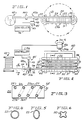
- FIG. 1 is a side elevational view of a simplified representation of a heat exchanger assembly and apparatus for producing the heat exchanger assembly in accordance with the present invention;
- FIG. 2 is a top plan view of a simplified representation of the heat exchanger assembly and the apparatus illustrated in FIG. 1;
- FIG. 3 is an end view of a heat exchanger assembly produced in accordance with the present invention;
- FIG. 4 is a cross-sectional view of the heat exchanger tube taken along the lines 4-4 of FIG. 2;
- FIG. 5 is a cross-sectional view of the heat exchanger tube taken along lines 5-5 of FIG. 2;
- FIG. 6 is a sectional view of the heat exchanger tube taken along the lines 6-6 of FIG. 2;
- FIG. 7 is a sectional view of the heat exchanger assembly taken along the lines 7-7 of FIG. 2;
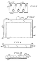
- FIG. 8 is a top plan view of the winding mandrel of the apparatus illustrated in FIG. 1 with a fin unit shown in phantom;
- FIG. 9 is a front elevational view of the mandrel illustrated in FIG. 1;
- FIG. 10 is a side elevational view of the mandrel illustrated in FIG. 1;
- FIG. 11 is a side elevational view of a form member of the apparatus illustrated in FIG. 1;
- FIG. 12 is a front elevational view of a pair of adjacent form members such as the one illustrated in FIG. 11;
- FIG. 13 is a side elevational view of a form member and a portion of the winding mandrel cooperating in forming a return bend for the heat exchanger tube;
- FIG. 13A is a sectional view taken along the
lines 13A-13A of FIG. 13; - FIG. 13B is a sectional view taken along the
lines 13B-13B of FIG. 13; - FIG. 13C is a sectional view taken along the lines 13C-13C of FIG. 13;
- FIG. 14 is a simplified representation of a heat exchanger assembly illustrating expansion of the pass portions of the tubing during the manufacturing of the heat exchanger assembly;
- FIG. 15 illustrates the cross-section of tube return bend portions for the completed heat exchanger assembly;
- FIG. 16 illustrates the cross-section of tube pass portions for the completed heat exchanger assembly;
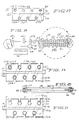
- FIG. 17 is an end view of a heat exchanger assembly having a plurality of fin units and which is produced in accordance with the present invention;
- FIG. 18 is a side elevational view of a simplified representation of the heat exchanger assembly of FIG. 17 which has a plurality of fin units and apparatus provided by the present invention for producing the heat exchanger assembly.
- FIG. 19 is a sectional view of the heat exchanger assembly;
- FIG. 20 is a front sectional view of the mandrel of the apparatus of FIG. 8; and
- FIG. 21 is a simplified representation of a heat exchanger assembly having a plurality of fin units, illustrating expansion of the pass portions of the tubing during the manufacturing of the heat exchanger assembly.
- Referring to FIGS. 1 and 2, there is shown a simplified representation of a
heat exchanger assembly 20 and apparatus for producing the heat exchanger assembly in accordance with the present invention. Theheat exchanger assembly 20 shown in FIGS. 1, 2 and 3, includes a heat transfer array including at least onefin unit 21 and a one-pieceheat exchanger tube 22. The fin unit defines a plurality of rows of aligned notches orslots 25 and 25a, in its upper surface 26 and its lower surface 26a, respectively. The single length of tube is wrapped around the fin unit threading or laid in the series ofnotches 25, 25a provided in respective surfaces 26, 26a of the fin unit. The fin unit is of the side-entry type and is formed from a single thin sheet of metal, such as aluminum, which is folded back and forth upon itself defining a plurality offins circular portion 27 and anarrow throat portion 27a. By way of example, the heat transfer array may be similar to that illustrated in FIG. 9 of U.S. Patent No. 4,881,311, including a single fin unit having notches in both surfaces. - The
heat exchanger tube 22 is formed of a bendable material, such as aluminum, and preferably consists of a unitary tubular member of circular cross-section having a diameter of about 0.375 inches and a wall thickness of about 0.016 inches. A heat exchanger tube having such dimensions affords sufficient mechanical strength to withstand internal pressure without rupturing while being capable of being compressed when subjected to forces on opposite sides of the tube, to facilitate insertion into the fin units. When thetube 22 is assembled with the fin unit, as shown in FIG. 2, it is formed into a pattern having an upper row ofpasses 30 and a lower row of passes 31. At the left-hand side of the assembly (as viewed in FIG. 2), the adjacent passes 30 and 31 in each of the upper and lower rows are interconnected at their ends byreturn bend portions 32 of the one-piece tube 22. Similarly, at the right-hand side of the assembly, thepasses return bend portions 33. One of the passes extends outwardly beyond thefin unit 21 to define a fluid inlet 34 (FIG. 2) for thetube 22, and one of the passes extends outwardly from the fin unit to define a fluid outlet 35 (FIG. 3) for the tube. - Referring to FIGS. 1 and 2, the apparatus for producing the heat exchanger assembly includes a
rotating mandrel 40, shapingapparatus 44,guide apparatus 45 and a plurality ofform guide members 60 associated with the mandrel. Themandrel 40 supports thefin unit 21 for rotation about anaxis 41 while drawing thetube 22 from a source 42 of tubing. In practice, the source of tubing 42 is located ten to twelve feet away from the winding mandrel. Theform guide members 60 are carried by and cooperate with the mandrel to define forming channels which define the pitch of thereturn bend portions tube 22. - The
tube 22 is drawn through the shapingapparatus 44 which compresses the tube vertically as viewed in FIG. 1, to change the shape of the tube from its generally circular cross section as illustrated in FIG. 4 to a generally circular cross section as illustrated in FIG. 5. The tube is flattened slightly to the oval shape to facilitate laying thetube 22 into thenotches 25, 25a of thefin unit 21, as illustrated in FIG. 7, as the tube is wrapped onto the fin unit. It is pointed out that tube segments of oval cross section and pre cut to predetermined lengths could be used rather than continuous length tubing which is cut to the desired length after being wrapped onto the fin unit. - The
guide apparatus 45 is operated by acontroller 46 and includes aguide arm 47 terminating inguide portion 47a which directs and lifts thetube 22, indexing the end of the tube for its insertion into thenotches 25, 25a as thefin unit 21 is rotated by themandrel 40. The phrase "end of the tube" means that portion of the tube being inserted into the notches at any given time during the wrapping process. Thecontroller 46 senses the position of the end of theheat exchanger tube 22 as the tube is being laid in each row of notches of the fin unit and repositions theguide arm 47 and the tube carried thereby at the end of each pass. For example, the position of the end of the tube in the fin unit may be correlated to the angular position of themandrel 40. That is, when the mandrel is oriented horizontally, as illustrated in FIG. 1, the tube is being laid in the middle portion of the row of notches on the upper surface of the fin unit. With 90° of rotation, the mandrel is oriented vertically and a return bend is being formed, etc. - The
guide arm 47 is carried by adrive mechanism 48 which rides on atrack 49 which extends transversely of the end of thefin unit 21. By way of example, thetrack 49 may comprise an operating screw arranged to move thedrive mechanism 48 and theguide arm 47 forward, in the direction of the arrow 48a (FIG. 2) one inch and then backwards one-half inch, a distance corresponding to the separation between adjacent passes of thetube 22 as wound on thefin unit 21. Thus with each forward movement of thedrive mechanism 48, the tube is advanced approximately one-half inch in the forward direction so as to be aligned with the next row of notches. Thedrive mechanism 48 is advanced with each 180° rotation of therotating mandrel 40 so that the end of the tube is aligned or indexed alternately with the notches on the upper and lower surfaces of the fin unit as the fin unit is rotated by themandrel 40. Thedrive mechanism 48 is moved as the fin unit is approaching a generally vertical orientation ( i. e., 90° of rotation from the position illustrated in FIG. 1). - Referring to FIGS. 8-12, the rotating
mandrel 40 includes ayoke 51 having a pair ofsupport arms support arms fin unit 21 therebetween. The foldedfin unit 21 affords sufficient resilience so as to be self-supporting between thesupport arms outer surfaces 55 of both support arms have a convex curved configuration as illustrated in FIG. 9. Each of thesupport arms holes 56 formed in theirouter surfaces 55 for indexing and maintaining theform devices 60 on themandrel 40. Theyoke 51 is coupled to asuitable drive mechanism 56 for rotation thereby. - Each of the
form guide members 60 is a generally C-shaped member, of phenolic or other rigid plastic material, with itsends inner surface 65. The distance "s" between the centerline ofend 61 and the centerline ofend 62 corresponds to the amount of displacement of the return bend portion of the tube, which in turn corresponds to the spacing between the upper and lower slots (FIG. 7). In the exemplary embodiment, the spacing is one-half inch. The radius of curvature "r" ofinner surface 65 of theform guide member 60 corresponds to the radius of curvature of theouter surfaces 55 of themandrel support arms form guide member 60 includes a pair of laterally offset, horizontally extendingpins 66 which are received in theholes 56 in thesupport arms form guide member 60 includes ametallic support plate 68 at its rearward side which interconnects thepins 66 and may cooperate with a positioning apparatus (not shown) to remove the form members from the mandrel after forming the return bends of thetube 22. - Referring to FIGS. 1, 2, 8 and 11-13, the
form members 60 are mounted on themandrel 40 prior to a tube wrapping operation. In the exemplary embodiment wherein the fin unit has four rows of notches provided on its upper surface and three rows notches provided on its lower surface, five form members are mounted on each of the twosupport arms pins 66 extending into the corresponding pair ofholes 56. The tolerance between thepins 66 and theholes 56 is such as to provide an interference fit. When theform members 60 are mounted on themandrel 40, the mandrel curved outer edge surfaces 55 are received betweenends form members 60. Theform members 60 are spaced apart from one another laterally defining a generally diagonal space or channel 70 (FIG. 2) between one row of notches on the upper surface and an adjacent row of notches on the lower surface. The shape of thediagonal space 70 corresponds to the pitch of the return bends. Aportion 55a of thecurved edge 55 of the mandrel support arm between adjacent form members is exposed in thespace 70 as illustrated in FIG. 13. - Referring to FIGS. 1 and 2, in manufacturing of the
heat exchanger assembly 20 in accordance with the present invention, afin unit 21 is mounted on themandrel 40. Then the free end of theheat exchanger tube 22 is drawn manually from the source 42 through the shapingapparatus 44 and laid in the first row of notches, and pushed thereonto. When the tube is seated in the first row of notches the tube is secured to the fin unit. Then thedrive mechanism 56 is activated to rotate themandrel 40 clockwise during the wrapping operation, as illustrated in FIG. 1, drawing thetube 22 from the source 42 of tubing. As the tube is drawn through the shapingapparatus 44, its cross section is formed to a generally oval shape as illustrated in FIG. 5. - As the mandrel reaches a vertical position, the
guide arm 47 is moved to redirect theovalized tube 22 throughform members 60 which define the first return bend to orient the tube to be directed into the first row of notches on the lower surface of the fin unit as themandrel 40 rotates. Referring to FIGS. 13A-13B, when the tube is initially positioned between form guides 60, as the mandrel approaches a vertical position, it is spaced from thesurface 55a of the mandrel (FIG. 13A). As the mandrel rotates to a vertical position, thetube 22 is pulled againstsurface 55a (FIG. 13B). With continued rotation, tension on thetube 22 while it engagessurfaces controller 46 senses the end of the row of notches and raises the end of the tube and moves the end of the tube forward to the next row of notches on the lower surface of the fin unit which has rotated 180°. The wrapping process continues until the tube is wrapped around thefin unit 21 and is laid in each of the rows of notches. Thetube pass portions bend portions - Thus, the
mandrel 40 rotates thefin unit 21 during wrapping of thetube 22 thereon, thesupport arms form guide members 60 to form the return bends 32 and 33 in the tube at its return bend portions. In accordance with a feature of the invention, thepass sections tube 22 extending along both the upper end lower surfaces of thefin unit 21 are parallel to one another. The offset portions of the tube are formed only at the return bend portions of the tube at the edges of the fin unit. Theform guide members 60 and thesupport arms fin unit 21. - After the
tube 22 has been wrapped around thefin unit 21 and is laid in thenotches 25 and 25a, the tube is severed from the supply, defining thefluid outlet 35. - Then, with the
form guide members 60 still in place, a pushing device 72, (FIG. 14) is deployed to push the tube pass portions, seating them in the notches. The pushing device may be in the form of upper and lower magazines each including a plurality oftines 72a adapted to engage the tube along each of itspass portions notches 25 and 25a during expansion of the tube. - Then, the
fluid outlet 35 of thetube 22 is closed and the tube is expanded by applying internal pressure to the tube through itsfluid inlet 34. Pressure in the order of 400 to 900 psi is applied, simultaneously expanding thepass portions return bend portions tube 22. The pushing device 72 prevents the tube from expanding back into the narrow throat portions of the slots so that the resultant cross section of thepass portions form devices 60 and thecurved surface portions 55a of the mandrel serve as form retainers to maintain the generally square cross section for thereturn bend portions - After the tube has been expanded, the pushing device 72 is retracted and the
form guide members 60 are removed in a suitable manner either manually, or automatically as by coupling theirmetallic support plates 68 to a positioning apparatus (not shown). In the fin section it may be preferable to strike the tube a second time with device 72 to form the tube in the "D" shape if the pressure P is high for tube expansion. Because theform members 60 are made of phenolic or the like, their side surfaces 63 and 64 which are engaging the tube return bends are slippery, facilitating their removal. When the form guide members are removed, the heat exchanger assembly can be slipped off of the mandrel. - Referring to FIGS. 17-19, in accordance with a further embodiment of the invention, a
heat exchanger assembly 20′ includes a heat transfer array 120 having a pair offin units 121 and 121a. The heat transfer array 120 may be similar to the heat transfer array including two fin units as illustrated in FIG. 5 of U.S. Patent No. 4,811,311.Fin unit 121 defines a plurality of rows of aligned notches orslots 125 in itsouter surface 126 which defines the upper surface of the heat transfer array 120. Similarly, fin unit 121a defines a plurality of aligned notches or slots 125a in itsouter surface 126a which defines the lower surface of the heat transfer array 120. Thefin units 121 and 121a have respective inner orrearward surfaces 127 and 127a. Thefin units 121 and 121a are positioned in back-to-back relation with their respectiverearward surfaces 127 and 127a adjacent to one another either in contact with one another or in a spaced relation as illustrated in FIGS. 17-19. - The
heat exchanger tube 22 is wrapped around the heat transfer array 120 formed by the twofin units 121 and 121a to form the heat exchanger assembly 20'. - Referring to FIG. 18, the method and apparatus for wrapping the
heat exchanger tube 22 onto the heat transfer array 120 is substantially the same as that described above forheat exchanger assembly 20. However, themandrel 40 includes means for maintaining the twofin units 121 and 121a in a spaced relationship while rotating the heat transfer array 120 and drawing thetube 22 from the source 42 of tubing. Referring to FIGS. 18-20, by way of example, thefin units 121 and 121a are maintained in spaced relation by inwardly directed projections 140 which extend along theinner surfaces 52a, 53a and 54b of thesupport arms mandrel 40. The length of the projections 140 is sufficient to support thefin units 121 and 121a on themandrel 40, and the height of the projections 140 is predetermined to establish a desired spacing between therearward surfaces 127 and 127a of the twofin units 121 and 121a. - After the
tube 22 has been wrapped around the heat transfer array 120 and is layed in thenotches 125 and 125a, then with theform guide members 60 still in place, pushing device 72 (FIG. 21) is deployed to push the tube passportions 30 and 31, seating them in the notches, in the manner described with reference to the manufacturing of theheat exchanger assembly 20. Thetube 22 is expanded by applying internal pressure to the tube through itsfluid inlet 34, expanding thepass portions return bend portions pass portions tube 22 engage the edges of the notches of thefin units 121 and 121a, mechanically connecting thefin units 121 and 121a to theheat exchanger tube 22. After the tube has been expanded, the pushing device 72 is retracted and theform guide members 60 are removed, permitting the completed heat exchanger assembly 20' to be slid off themandrel 40.
Claims (13)
- A method of making a heat exchanger assembly (20) of the type including a heat transfer array having at least one fin unit (21), said heat transfer array having opposed first and second sides and defining a plurality of fins, each of the fins having notches (25, 25a) which are aligned in sets on the first (26) and second (26a) sides with the sets of notches on the first side being offset relative to the sets of notches on the second side, and a single length of heat exchanger tube (22) applied to the heat transfer array, threading the notches in the fins thereof, defining a first plurality of pass sections threading the notches on the first side and a second plurality of parallel passes threading the notches on the second side, and return bend portions (32, 33) interconnecting adjacent pass portions on the first and second sides, characterised in that the method comprises:
wrapping the heat exchanger tube (22) around the heat transfer array;
guiding the tube (22) as it is wrapped around the heat transfer array so as to direct the tube (22) alternatively into sets of notches (25,25a) on the first and second sides (26,26a);
maintaining tension on the heat exchanger tube (22) while it is being wrapped around the heat transfer array, threading the notches (25,25a) of the fins thereof, to thereby produce a deformed cross section for the tube (22) in the return bend portions (32,33) with a plurality of inwardly directed rib portions;
and, upon completion of the wrapping of the tube (22) onto the heat transfer array, expanding the return bend portions (32,33) to a generally rectangular shape to increase the internal cross sectional area of the tube in the return bend portions. - A method according to claim 1, characterised in that said heat transfer array (120) comprises first (121) and second (121a) fin units and in that the method further comprises supporting said first and second fin units on a support structure (140) in back-to-back relation prior to wrapping the tube, with said first fin unit defining said first side of said heat transfer array and said second fin unit defining said second side of said heat transfer array.
- A method according to claim 1, characterised in that the tube is wrapped onto the heat transfer array by rotating the heat transfer array about an axis while drawing the tube onto the heat transfer array, and in that the tube is guided onto the heat transfer array as it is wrapped by monitoring the position of the tube as it is being laid in each set of notches in the heat transfer array and controlling a guide arm(47) to redirect the tube relative to each set of notches in the heat transfer array as the heat transfer array is rotated about said axis.
- A method according to claim 3, characterised in that the guide arm is moved transversely of the heat transfer array a distance correlated with the amount of offset between sets of notches on the first and second sides of the heat transfer array.
- A method according to any one of the preceding claims, characterised in that the tube is reshaped from a generally circular cross section to a generally oval cross section prior to wrapping the tube onto the heat transfer array, and in that the pass portions are expanded from a generally oval cross section to a generally circular cross section simultaneously with the expansion of the return bend portions.
- A method according to any one of the preceding claims, characterised in that guiding of the tube includes providing forming means (60) to define the pitch for each return bend portion for directing the tube between sets of notches on the first and second sides.
- A method according to claim 6, characterised in that the forming means is removably mounted on a support structure (51) which supports the heat transfer array while the tube is being wrapped thereon, in that the forming means are maintained adjacent to each return bend portion of the heat exchanger tube during expanding of the tube, and in that the forming means is removed from the support structure after the return end portions have been expanded.
- Apparatus for producing a heat exchanger assembly (20) of the type including a heat transfer array having at least one fin unit (21), said heat transfer array having opposed first (26) and second (26a) sides and having fins with notches (25, 25a) therein aligned in sets on the first and second sides, and a single length of heat exchanger tube (22) mounted on the heat transfer array and defining pass portions threading the notches on the first and second sides and return bend portions (32, 33) interconnecting the pass portions on the first and second sides, characterised in that said apparatus comprises:
means (4) for producing relative rotation between the heat transfer array and means (42) for feeding the heat exchanger tube (22) to the heat transfer array for wrapping the heat exchanger tube onto the heat transfer array;
guiding means (45) for guiding the tube relative to the heat transfer array as the tube is being wrapped thereon to direct the tube alternatively into a set of notches on the first and second sides;
means (44) for maintaining tension on said heat exchanger tube as it is being wrapped onto the heat transfer array;
forming means (60) defining the pitch of the return bend portions of the heat exchanger tube as it is being wrapped onto the heat transfer array;
said forming means (60) being constructed and arranged to maintain substantially square cross section for the return bend portions (32,33) during subsequent expansion of the heat exchanger tube (22). - Apparatus according to claim 8, in which said heat transfer array (120) comprises first (121) and second fin (121a) units, characterised in that the apparatus further comprises a support structure (140) for supporting said first and second fin units in back-to-back relation with said first fin unit defining said first side of said heat transfer array and said second fin unit defining said second side of said heat transfer array.
- Apparatus according to claim 8 or 9, characterised in that said forming means comprises a plurality of forming devices (60) cooperating in pairs to define the pitch of the return bend portions of said heat exchanger tube, each device having a generally C-shaped configuration with first (61) and second (62) ends offset axially a distance corresponding to the axis of adjacent rows of notches in the upper and lower sides of the heat transfer array.
- Apparatus according to claim 10, characterised in that it includes a supporting structure (51) for supporting the heat transfer array while the tube is being wrapped thereon, said forming devices (60) being removably mountable on said supporting structure and each said forming device having locating means (56) for locating said forming devices on said supporting structure, adjacent forming devices being spaced apart from one another and defining a channel (70) therebetween, the shape of the channel defining the pitch of the return bend portions.
- Apparatus according to claim 11, characterised in that said supporting structure has first (52) and second (53) parallel opposing support arms adapted to receive and support the heat transfer until therebetween, the radius of curvature of the inner surface of each said forming device conforming generally to the radius of the curvature of an outer surface of the support arms, and the tube being wrapped around the heat transfer array and the support arms.
- Apparatus according to any one of claims 8 to 12 characterised by means (40) for rotating the heat transfer array about an axis while drawing the tube onto the heat transfer array, said guiding means including a guide arm (47) and controller means (46) for controlling the positioning of said guide arm to redirect the tube relative to each set of notches in the heat transfer array as the heat transfer array is rotated about said axis, and means (48) for moving said guide arm transversely of the heat transfer array a distance correlated with the amount of offset between sets of notches on the first and second sides of the heat transfer array.
Priority Applications (1)
| Application Number | Priority Date | Filing Date | Title |
|---|---|---|---|
| AT91310904T ATE104183T1 (en) | 1990-11-29 | 1991-11-27 | HEAT EXCHANGER WITH COILED TUBES. |
Applications Claiming Priority (4)
| Application Number | Priority Date | Filing Date | Title |
|---|---|---|---|
| US619869 | 1990-11-29 | ||
| US07/619,869 US5099574A (en) | 1990-11-29 | 1990-11-29 | Method of making a heat exchanger assembly with wrapped tubing |
| US07/777,026 US5228198A (en) | 1990-11-29 | 1991-10-16 | Method of manufacturing a heat exchanger assembly with wrapped tubing |
| US777026 | 2001-02-05 |
Publications (2)
| Publication Number | Publication Date |
|---|---|
| EP0488664A1 EP0488664A1 (en) | 1992-06-03 |
| EP0488664B1 true EP0488664B1 (en) | 1994-04-13 |
Family
ID=27088611
Family Applications (1)
| Application Number | Title | Priority Date | Filing Date |
|---|---|---|---|
| EP91310904A Expired - Lifetime EP0488664B1 (en) | 1990-11-29 | 1991-11-27 | Heat exchanger assembly with wrapped tubing |
Country Status (7)
| Country | Link |
|---|---|
| US (1) | US5228198A (en) |
| EP (1) | EP0488664B1 (en) |
| JP (1) | JPH0759332B2 (en) |
| KR (1) | KR920009503A (en) |
| CA (1) | CA2056273C (en) |
| DE (1) | DE69101694T2 (en) |
| ES (1) | ES2053288T3 (en) |
Families Citing this family (13)
| Publication number | Priority date | Publication date | Assignee | Title |
|---|---|---|---|---|
| US20040079522A1 (en) * | 1995-11-13 | 2004-04-29 | Roger Paulman | Folded, bent and re-expanded heat exchanger tube and assemblies |
| US5704123A (en) * | 1995-11-13 | 1998-01-06 | Peerless Of America, Incorporated | Method of making folded, bent and re-expanded heat exchanger tube and assemblies |
| US5682783A (en) * | 1996-04-23 | 1997-11-04 | Mill Masters, Inc. | Ceramic tubemill roll assembly |
| US5737828A (en) * | 1996-06-19 | 1998-04-14 | American Standard Inc. | Continuous heat exchanger forming apparatus |
| US5952067A (en) * | 1996-12-02 | 1999-09-14 | A&P Technology, Inc. | Braided structure having uncrimped strands |
| US6253839B1 (en) | 1999-03-10 | 2001-07-03 | Ti Group Automotive Systems Corp. | Refrigeration evaporator |
| ATE201761T1 (en) * | 1999-10-07 | 2001-06-15 | Giannoni S P A | GAS-LIQUID HEAT EXCHANGER AND METHOD FOR THE PRODUCTION THEREOF |
| US6715202B2 (en) | 2001-11-02 | 2004-04-06 | American Standard International Inc. | Tube bender for forming serpentine heat exchangers from spine fin tubing |
| US7028764B2 (en) * | 2002-03-01 | 2006-04-18 | Ti Group Automotives Systems, Llc | Refrigeration evaporator |
| US8235100B2 (en) * | 2003-11-17 | 2012-08-07 | Melter, S.A. De C.V. | Water cooled panel |
| MXNL03000043A (en) * | 2003-11-17 | 2005-05-20 | Melter S A De C V | Water cooled panel and forming method. |
| CN106424256A (en) * | 2016-10-26 | 2017-02-22 | 中国电子科技集团公司第四十八研究所 | Machining device for spiral copper tube and machining method thereof |
| EP3686714A1 (en) * | 2019-01-25 | 2020-07-29 | Asetek Danmark A/S | Cooling system including a heat exchanging unit |
Family Cites Families (10)
| Publication number | Priority date | Publication date | Assignee | Title |
|---|---|---|---|---|
| US1802161A (en) * | 1926-11-06 | 1931-04-21 | Frigidaire Corp | Method of and apparatus for forming coils |
| US2204613A (en) * | 1935-06-29 | 1940-06-18 | Hoover Co | Heat exchanger |
| US2771934A (en) * | 1951-06-28 | 1956-11-27 | Vapor Heating Corp | Apparatus for forming tubing into coils |
| GB914083A (en) * | 1960-10-13 | 1962-12-28 | Bundy Tubing Co | Improvements in or relating to heat exchange coils and method and apparatus for manufacturing the same |
| US3712372A (en) * | 1971-03-01 | 1973-01-23 | Oilin Corp | Method and apparatus for deforming a flat on parts of metal strip-type tubing while leaving other parts undeformed |
| DE2230086C3 (en) * | 1972-06-21 | 1975-06-26 | Joh. Vaillant Kg, 5630 Remscheid | Device for wrapping a sheet metal heating shaft with a water pipe |
| US3780799A (en) * | 1972-06-26 | 1973-12-25 | Peerless Of America | Heat exchangers and method of making same |
| US4241785A (en) * | 1978-07-24 | 1980-12-30 | Peerless Of America, Inc. | Heat exchangers and method of making same |
| US4778004A (en) * | 1986-12-10 | 1988-10-18 | Peerless Of America Incorporated | Heat exchanger assembly with integral fin unit |
| US4881311A (en) * | 1986-12-10 | 1989-11-21 | Peerless Of America Incorporated | Heat exchanger assembly with integral fin unit |
-
1991
- 1991-10-16 US US07/777,026 patent/US5228198A/en not_active Expired - Lifetime
- 1991-11-19 KR KR1019910021738A patent/KR920009503A/en not_active Ceased
- 1991-11-22 JP JP3307411A patent/JPH0759332B2/en not_active Expired - Lifetime
- 1991-11-27 EP EP91310904A patent/EP0488664B1/en not_active Expired - Lifetime
- 1991-11-27 CA CA002056273A patent/CA2056273C/en not_active Expired - Fee Related
- 1991-11-27 ES ES91310904T patent/ES2053288T3/en not_active Expired - Lifetime
- 1991-11-27 DE DE69101694T patent/DE69101694T2/en not_active Expired - Fee Related
Also Published As
| Publication number | Publication date |
|---|---|
| EP0488664A1 (en) | 1992-06-03 |
| US5228198A (en) | 1993-07-20 |
| KR920009503A (en) | 1992-06-25 |
| JPH0759332B2 (en) | 1995-06-28 |
| JPH04266439A (en) | 1992-09-22 |
| DE69101694T2 (en) | 1994-07-28 |
| ES2053288T3 (en) | 1994-07-16 |
| DE69101694D1 (en) | 1994-05-19 |
| CA2056273C (en) | 1995-12-05 |
| CA2056273A1 (en) | 1992-05-30 |
Similar Documents
| Publication | Publication Date | Title |
|---|---|---|
| CA2056273C (en) | Heat exchanger assembly with wrapped tubing | |
| CA1297471C (en) | Heat exchanger assembly with integral fin units | |
| KR101345995B1 (en) | Holder for pipe in heat exchanger, method and device for manufacturing heat exchanger using said holder, and air conditioner and/or outdoor unit having said heat exchanger | |
| US5142895A (en) | Method for bending tubes | |
| JP2977824B2 (en) | Double-row heat exchanger and method of manufacturing the same | |
| KR20140023431A (en) | Manufacturing method for grip member for insertion tube in heat exchanger, manufacturing method for heat exchanger using said grip member, and air conditioner and/or outdoor unit having said heat exchanger | |
| CA1252272A (en) | Method of manufacturing fin-tube heat exchangers | |
| US5284041A (en) | Method for bending tubes using split die | |
| CN1476360A (en) | Coil and coil head forming die for coil with unconventional terminal convolutions | |
| US4566359A (en) | Method of stacking fins of heat exchangers | |
| US5099574A (en) | Method of making a heat exchanger assembly with wrapped tubing | |
| JPH09203594A (en) | Folded and re-expanded heat exchanger pipe and its assembly | |
| JPH07251317A (en) | Method for producing flat tube for heat exchanger | |
| JPH07178486A (en) | Method and device for manufacturing header tank of heat exchanger | |
| US4519121A (en) | Method of and apparatus for mounting plate fins of hairpin pipes | |
| US7553148B2 (en) | Production apparatus and production method for producing bent portion of multi-channel tube | |
| US4619024A (en) | Method of making coils | |
| US4770241A (en) | Method and apparatus for forming slit fin coils | |
| US6212764B1 (en) | Link bending machine | |
| CN219309921U (en) | Production line of coiled heat exchange tube | |
| JPS59153532A (en) | Production of heat exchanger | |
| CN215199066U (en) | Pipe fitting finishing device and two-device production system | |
| WO2005072439A2 (en) | Sprocket tube inserter for heat exchanger manufacturing | |
| EP0223534B1 (en) | Heat exchangers | |
| KR940008540B1 (en) | Manufacturing method of fin tube for heat exchange |
Legal Events
| Date | Code | Title | Description |
|---|---|---|---|
| PUAI | Public reference made under article 153(3) epc to a published international application that has entered the european phase |
Free format text: ORIGINAL CODE: 0009012 |
|
| AK | Designated contracting states |
Kind code of ref document: A1 Designated state(s): AT DE ES FR GB IT NL SE |
|
| RAP1 | Party data changed (applicant data changed or rights of an application transferred) |
Owner name: PEERLESS OF AMERICA, INCORPORATED |
|
| 17P | Request for examination filed |
Effective date: 19920827 |
|
| 17Q | First examination report despatched |
Effective date: 19930617 |
|
| GRAA | (expected) grant |
Free format text: ORIGINAL CODE: 0009210 |
|
| AK | Designated contracting states |
Kind code of ref document: B1 Designated state(s): AT DE ES FR GB IT NL SE |
|
| REF | Corresponds to: |
Ref document number: 104183 Country of ref document: AT Date of ref document: 19940415 Kind code of ref document: T |
|
| REF | Corresponds to: |
Ref document number: 69101694 Country of ref document: DE Date of ref document: 19940519 |
|
| ITF | It: translation for a ep patent filed | ||
| REG | Reference to a national code |
Ref country code: ES Ref legal event code: FG2A Ref document number: 2053288 Country of ref document: ES Kind code of ref document: T3 |
|
| ET | Fr: translation filed | ||
| PGFP | Annual fee paid to national office [announced via postgrant information from national office to epo] |
Ref country code: AT Payment date: 19941017 Year of fee payment: 4 |
|
| PGFP | Annual fee paid to national office [announced via postgrant information from national office to epo] |
Ref country code: NL Payment date: 19941130 Year of fee payment: 4 |
|
| EAL | Se: european patent in force in sweden |
Ref document number: 91310904.7 |
|
| PLBE | No opposition filed within time limit |
Free format text: ORIGINAL CODE: 0009261 |
|
| STAA | Information on the status of an ep patent application or granted ep patent |
Free format text: STATUS: NO OPPOSITION FILED WITHIN TIME LIMIT |
|
| 26N | No opposition filed | ||
| PG25 | Lapsed in a contracting state [announced via postgrant information from national office to epo] |
Ref country code: AT Effective date: 19951127 |
|
| PG25 | Lapsed in a contracting state [announced via postgrant information from national office to epo] |
Ref country code: NL Effective date: 19960601 |
|
| NLV4 | Nl: lapsed or anulled due to non-payment of the annual fee |
Effective date: 19960601 |
|
| REG | Reference to a national code |
Ref country code: GB Ref legal event code: IF02 |
|
| PGFP | Annual fee paid to national office [announced via postgrant information from national office to epo] |
Ref country code: ES Payment date: 20081118 Year of fee payment: 18 |
|
| PGFP | Annual fee paid to national office [announced via postgrant information from national office to epo] |
Ref country code: SE Payment date: 20081107 Year of fee payment: 18 Ref country code: IT Payment date: 20081118 Year of fee payment: 18 |
|
| PGFP | Annual fee paid to national office [announced via postgrant information from national office to epo] |
Ref country code: FR Payment date: 20081106 Year of fee payment: 18 |
|
| PGFP | Annual fee paid to national office [announced via postgrant information from national office to epo] |
Ref country code: DE Payment date: 20081128 Year of fee payment: 18 |
|
| PGFP | Annual fee paid to national office [announced via postgrant information from national office to epo] |
Ref country code: GB Payment date: 20081008 Year of fee payment: 18 |
|
| EUG | Se: european patent has lapsed | ||
| GBPC | Gb: european patent ceased through non-payment of renewal fee |
Effective date: 20091127 |
|
| REG | Reference to a national code |
Ref country code: FR Ref legal event code: ST Effective date: 20100730 |
|
| PG25 | Lapsed in a contracting state [announced via postgrant information from national office to epo] |
Ref country code: FR Free format text: LAPSE BECAUSE OF NON-PAYMENT OF DUE FEES Effective date: 20091130 |
|
| PG25 | Lapsed in a contracting state [announced via postgrant information from national office to epo] |
Ref country code: DE Free format text: LAPSE BECAUSE OF NON-PAYMENT OF DUE FEES Effective date: 20100601 |
|
| PG25 | Lapsed in a contracting state [announced via postgrant information from national office to epo] |
Ref country code: GB Free format text: LAPSE BECAUSE OF NON-PAYMENT OF DUE FEES Effective date: 20091127 |
|
| REG | Reference to a national code |
Ref country code: ES Ref legal event code: FD2A Effective date: 20110307 |
|
| PG25 | Lapsed in a contracting state [announced via postgrant information from national office to epo] |
Ref country code: IT Free format text: LAPSE BECAUSE OF NON-PAYMENT OF DUE FEES Effective date: 20091127 |
|
| PG25 | Lapsed in a contracting state [announced via postgrant information from national office to epo] |
Ref country code: SE Free format text: LAPSE BECAUSE OF NON-PAYMENT OF DUE FEES Effective date: 20091128 |
|
| PG25 | Lapsed in a contracting state [announced via postgrant information from national office to epo] |
Ref country code: ES Free format text: LAPSE BECAUSE OF NON-PAYMENT OF DUE FEES Effective date: 20110304 |
|
| PG25 | Lapsed in a contracting state [announced via postgrant information from national office to epo] |
Ref country code: ES Free format text: LAPSE BECAUSE OF NON-PAYMENT OF DUE FEES Effective date: 20091128 |