EP0488056A1 - Noise isolated amplifier circuit - Google Patents
Noise isolated amplifier circuit Download PDFInfo
- Publication number
- EP0488056A1 EP0488056A1 EP91119867A EP91119867A EP0488056A1 EP 0488056 A1 EP0488056 A1 EP 0488056A1 EP 91119867 A EP91119867 A EP 91119867A EP 91119867 A EP91119867 A EP 91119867A EP 0488056 A1 EP0488056 A1 EP 0488056A1
- Authority
- EP
- European Patent Office
- Prior art keywords
- input terminal
- emitter follower
- terminal
- ground
- output terminal
- Prior art date
- Legal status (The legal status is an assumption and is not a legal conclusion. Google has not performed a legal analysis and makes no representation as to the accuracy of the status listed.)
- Granted
Links
- 238000002955 isolation Methods 0.000 claims abstract description 19
- 239000003990 capacitor Substances 0.000 claims description 23
- 230000005236 sound signal Effects 0.000 claims description 6
- 239000000872 buffer Substances 0.000 description 5
- 238000010586 diagram Methods 0.000 description 4
- 238000012986 modification Methods 0.000 description 1
- 230000004048 modification Effects 0.000 description 1
Images

Classifications
-
- H—ELECTRICITY
- H03—ELECTRONIC CIRCUITRY
- H03F—AMPLIFIERS
- H03F3/00—Amplifiers with only discharge tubes or only semiconductor devices as amplifying elements
-
- H—ELECTRICITY
- H03—ELECTRONIC CIRCUITRY
- H03F—AMPLIFIERS
- H03F3/00—Amplifiers with only discharge tubes or only semiconductor devices as amplifying elements
- H03F3/68—Combinations of amplifiers, e.g. multi-channel amplifiers for stereophonics
-
- H—ELECTRICITY
- H03—ELECTRONIC CIRCUITRY
- H03F—AMPLIFIERS
- H03F1/00—Details of amplifiers with only discharge tubes, only semiconductor devices or only unspecified devices as amplifying elements
- H03F1/30—Modifications of amplifiers to reduce influence of variations of temperature or supply voltage or other physical parameters
- H03F1/302—Modifications of amplifiers to reduce influence of variations of temperature or supply voltage or other physical parameters in bipolar transistor amplifiers
-
- H—ELECTRICITY
- H03—ELECTRONIC CIRCUITRY
- H03F—AMPLIFIERS
- H03F3/00—Amplifiers with only discharge tubes or only semiconductor devices as amplifying elements
- H03F3/45—Differential amplifiers
- H03F3/45071—Differential amplifiers with semiconductor devices only
- H03F3/45479—Differential amplifiers with semiconductor devices only characterised by the way of common mode signal rejection
Definitions
- the present invention relates to an isolation amplifier circuit, and particularly, to an isolation amplifier circuit employed for a noise cancel circuit, etc. of an audio apparatus such as a stereo sound system, etc.
- noise induced by an engine, etc. easily intrudes into an audio power amplifier since a car body is used as a ground portion of a circuit, whereby sound quality is deteriorated. Thus, it is required to cancel the noise on the way to the audio power amplifier.
- Fig. 1 shows a conventional car audio circuit having a noise cancel circuit.
- the numeral 1 is a tuner deck having amplifiers 4 and 5 respectively connected to input terminals 2 and 3 to which audio signals of an L and R channels of a stereo are inputted. An output thereof is connected to input terminals 9 and 10 of a noise cancel circuit 8 through capacitors 6 and 7.
- the noise cancel circuit 8 is formed with an integrated circuit (IC).
- the input terminals 9 and 10 are connected to plus terminals of buffers 11 and 12.
- Output terminals of the buffers 11 and 12 are connected to plus terminals of operation amplifiers 13 and 14 through resistors R3 and R3'.
- Minus input terminals of the operation amplifiers 13 and 14 are connected to output terminals through resistors R2 and R2'.
- first common ground terminal 15 through resistors R1 and R1'.
- a capacitor 16 is connected to the first common ground terminal 15.
- the other end of the capacitor 16 is connected, together with the tuner block 1, to a car body 18 at a ground point 17.
- Plus input terminals of the operation amplifiers 13 and 14 are connected to a second common ground terminal 19 through resistors R4 and R4'.
- a capacitor 20 is connected to the second common ground terminal 19, a capacitor 20 is connected.
- the output terminals of the operation amplifiers 13 and 14 are connected to output terminals 21 and 22.
- the output terminals 21 and 22 are connected to audio power amplifiers 25 and 26 through capacitors 23 and 24.
- speakers 27 and 28 are connected as shown in the figure.
- Noise from a noise source 29 equivalently exists in the car body 1.
- the noise is divided into: noise which intrudes from the ground point 17 into the plus input terminal of the operation amplifier 13 for the L channel by way of the tuner deck 1, the amplifier 4, the terminal 9, and the buffer 11; noise which intrudes from the ground point 17 into the plus input terminal of the operation amplifier 14 for the R channel by way of the tuner deck 1, the amplifier 5, the terminal 10, and the buffer 12; noise which intrudes from the ground point 17 into the minus input terminal of the operation amplifier 13 for the L channel by way of the capacitor 16, the first common terminal 15, and the resistor R1; and noise which intrudes from the ground point 17 into the minus input terminal of the operation amplifier 14 for the R channel by way of the capacitor 16, the first common terminal 15, and the resistor R1'.
- noise cancel is interfered with when impedance connected to the first common ground terminal 15 is large.
- An object of the present invention is to provide an isolation amplifier circuit where a condition for noise cancel are fulfilled even if impedance connected to common ground terminals of an L and R channels is large.
- the isolation amplifier circuit is provided with: an operation amplifier having a first and second input terminals, an output terminal, and a feedback resistor for connecting the output terminal and second input terminal a first emitter follower, for inputting a signal, connected to the first input terminal; a second emitter follower connected between the output terminal and the feedback resistor; a third emitter follower connected between the second input terminal and a first ground impedance; a fourth emitter follower connected between the first input terminal and a second ground impedance; and means for making dynamic resistance of each of the first, second, third, and fourth emitter followers identical with one another.
- the isolation amplifier circuit for a car audio apparatus is provided with: an operation amplifier, for an L channel of a car stereo sound system, provided with a first and second input terminals, a first output terminal, and a first feedback resistor for connecting the first output terminal and a second output terminal; a first emitter follower, for inputting an L-channel audio signal, connected to the first input terminal; a second emitter follower connected between the first output terminal and the first feedback resistor; a third emitter follower connected between the second input terminal and a first ground impedance; a fourth emitter follower connected between the first input terminal and a second ground impedance; an operation amplifier, for an R channel of a car stereo apparatus, provided with a third and fourth input terminals, a second output terminal, and a second feedback resistor for connecting the second output terminal and the fourth input terminal; a fifth emitter follower, for inputting an R-channel audio signal, connected to the third input terminal; a sixth emitter follower connected between the second output terminal and
- the first and second ground impedances are equivalently converted into low impedance by the third and fourth emitter followers even if impedance thereof is high, impedance on the output side of the third and fourth emitter followers is not affected.
- a condition for canceling noise which intrudes into, for example, the first and second input terminals is never broken by the first and second ground impedances.
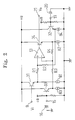
- an input signal is applied from an input terminal 9 to a plus input terminal (a first input terminal) of an operation amplifier 13 via an emitter follower 31 and a resistor R1.
- An output of the operation amplifier 13 is returned to a minus input terminal (a second input terminal) via an emitter follower 34 and a feedback resistor R4 connected to an output terminal as well as is directed to an output terminal 21.
- the minus input terminal is connected to a ground terminal 15 through a resistor R3 and an emitter follower 33.
- a capacitor 16 for grounding is connected.
- the plus input terminal is connected to a ground terminal 19 through a resistor R2 and a fourth emitter follower 32.
- To the ground terminal 19, a capacitor 20 is connected.
- capacity values of the capacitors 16 and 20 are small.
- impedance of the capacitors 16 and 20 is larger, sizes of the resistors R2 and R3 are hardly affected, since the impedance of each of the capacitors 16 and 20 is impedance-converted by the emitter followers 32 and 33 so that it becomes low on the output side (emitter side) of the emitter followers 32 and 33.
- the resistors R1, R2, R3, and R4 are connected to the emitter followers 31, 32, 33, and 34, respectively.
- the emitter followers 31, 32, 33, and 34 are provided to all of the resistors R1, R2, R3, and R4 in order to remove an influence of the dynamic resistance re.
- constant current sources 81, 82, 83, and 84 on the emitter side are identical in order to make identical dynamic resistors re1, re2, re3, and re4 of the emitter followers 31, 32, 33, and 34.
- the dynamic resistances are set by constant current sources, etc. provided to the emitters.
- an input signal from the input terminal 9 is inputted to the operation amplifier 13 through the emitter follower 31.
- the structure thereof is simpler compared to that of the conventional circuit (shown in Fig. 1) where the buffer 11 consists of an operation amplifier.
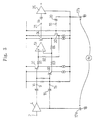
- Fig. 3 shows the above-described isolation amplifier circuit of Fig. 2 employed as a noise cancel circuit of a car audio apparatus.
- the numerals 4 and 25 are a preamplifier and an audio power amplifier, respectively. They are connected, together with a capacitor, to a car body 18 at ground points 17a and 17b.
- es a signal voltage outputted from an output terminal of the preamplifier 4
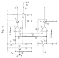
- Fig. 4 shows an embodiment where the isolation amplifier circuit of Fig. 2 is employed for both of the stereo L and R channels of a car audio apparatus.
- the ground terminals 15 and 19, and the third and fourth emitter followers 32 and 33 are used for both of the L and R channels.
- the numeral 13' is an operation amplifier for the R channel
- the numeral 33' is a fifth emitter follower to which an R-channel audio signal from an input terminal 10 is inputted
- the numeral 34' is a sixth emitter follower in a feedback path of the operation amplifier 13'.
- the capacitors 16 and 20 are connected to the ground terminals 15 and 19 in the above-described embodiments of Figs. 2, 3, and 4, it is not always necessary to connect capacitors to the ground terminals 15 and 19 in implementing the present invention.
- the ground terminal 15 may be connected through a line pattern. In that case, if a distance from the ground terminal 15 to a ground point is long, the line pattern has an adequate resistance, so that impedance becomes high. Thus, an implementation of the present invention is effective also in this case.
- the first and second ground impedances are equivalently converted into low impedance by the third and fourth emitter followers even if impedance thereof is high, impedance on the output side of the fourth emitter follower is not affected. Thus, a condition for canceling noise which intrudes into the first and second input terminals is never broken by the first and second ground impedances. Moreover, since the first and second impedances may be great, when capacitors are used as the first and second impedances, the capacity values of the capacitors can be small.
- the isolation amplifier circuit is employed for a noise cancel circuit of a car audio apparatus, high-quality sound is obtained which is not affected by noise from an engine, etc. and where there is no distortion.
- the whole circuit can be designed so as to be of simple structure.
Landscapes
- Engineering & Computer Science (AREA)
- Power Engineering (AREA)
- Amplifiers (AREA)
Abstract
Description
- The present invention relates to an isolation amplifier circuit, and particularly, to an isolation amplifier circuit employed for a noise cancel circuit, etc. of an audio apparatus such as a stereo sound system, etc.
- In a car audio apparatus such as a stereo sound system, etc. installed on a car, noise induced by an engine, etc. easily intrudes into an audio power amplifier since a car body is used as a ground portion of a circuit, whereby sound quality is deteriorated. Thus, it is required to cancel the noise on the way to the audio power amplifier.
- Fig. 1 shows a conventional car audio circuit having a noise cancel circuit. In the figure, the numeral 1 is a tuner
deck having amplifiers 4 and 5 respectively connected toinput terminals input terminals circuit 8 through capacitors 6 and 7. The noise cancelcircuit 8 is formed with an integrated circuit (IC). Theinput terminals buffers 11 and 12. Output terminals of thebuffers 11 and 12 are connected to plus terminals ofoperation amplifiers operation amplifiers common ground terminal 15 through resistors R1 and R1'. To the firstcommon ground terminal 15, acapacitor 16 is connected. The other end of thecapacitor 16 is connected, together with the tuner block 1, to acar body 18 at aground point 17. Plus input terminals of theoperation amplifiers common ground terminal 19 through resistors R4 and R4'. To the secondcommon ground terminal 19, acapacitor 20 is connected. The output terminals of theoperation amplifiers output terminals output terminals audio power amplifiers capacitors power amplifiers speakers 27 and 28 are connected as shown in the figure. - Next, an operation of the noise cancel
circuit 8 in the car audio circuit will be described. Noise from anoise source 29 equivalently exists in the car body 1. The noise is divided into: noise which intrudes from theground point 17 into the plus input terminal of theoperation amplifier 13 for the L channel by way of the tuner deck 1, theamplifier 4, theterminal 9, and the buffer 11; noise which intrudes from theground point 17 into the plus input terminal of theoperation amplifier 14 for the R channel by way of the tuner deck 1, the amplifier 5, theterminal 10, and thebuffer 12; noise which intrudes from theground point 17 into the minus input terminal of theoperation amplifier 13 for the L channel by way of thecapacitor 16, the firstcommon terminal 15, and the resistor R1; and noise which intrudes from theground point 17 into the minus input terminal of theoperation amplifier 14 for the R channel by way of thecapacitor 16, the firstcommon terminal 15, and the resistor R1'. - Only cancel of noise of the L channel will be described, since the principle of cancel of noise of the R channel is the same as that of the cancel of noise of the L channel. As described above, noise intrudes into the plus and minus input terminals of the
operation amplifier 13 for the L channel. If the noise intruding into the plus input terminal and the noise intruding into the minus input terminal are equal to each other in phase and size, the noises are canceled by a common-mode input rejection action of theoperation amplifier 13 for the L channel, so that the noises are not included in an output of theoperation amplifier 13 for the L channel. - For the above-described noise cancel, it is required that

- For the above-described conventional art, the capacity of the
capacitor 16 connected to the firstcommon ground terminal 15 has to be large. This is because if the capacity of thecapacitor 16 is small, impedance is large so that RI/R2=R3/R4 which is one of the conditions for noise cancel cannot be fulfilled since thecapacitor 16 is equivalently included by impedance of the resistor R1. For this reason, the capacity of thecapacitor 16 has to be large (impedance has to be small). - Moreover, in a circuit, for example, where the
capacitor 16 is not connected to the firstcommon ground terminal 15, noise cancel is interfered with when impedance connected to the firstcommon ground terminal 15 is large. - An object of the present invention is to provide an isolation amplifier circuit where a condition for noise cancel are fulfilled even if impedance connected to common ground terminals of an L and R channels is large.
- According to one feature of the present invention, the isolation amplifier circuit is provided with: an operation amplifier having a first and second input terminals, an output terminal, and a feedback resistor for connecting the output terminal and second input terminal a first emitter follower, for inputting a signal, connected to the first input terminal; a second emitter follower connected between the output terminal and the feedback resistor; a third emitter follower connected between the second input terminal and a first ground impedance; a fourth emitter follower connected between the first input terminal and a second ground impedance; and means for making dynamic resistance of each of the first, second, third, and fourth emitter followers identical with one another.
- According to another feature of the present invention, the isolation amplifier circuit for a car audio apparatus is provided with: an operation amplifier, for an L channel of a car stereo sound system, provided with a first and second input terminals, a first output terminal, and a first feedback resistor for connecting the first output terminal and a second output terminal; a first emitter follower, for inputting an L-channel audio signal, connected to the first input terminal; a second emitter follower connected between the first output terminal and the first feedback resistor; a third emitter follower connected between the second input terminal and a first ground impedance; a fourth emitter follower connected between the first input terminal and a second ground impedance; an operation amplifier, for an R channel of a car stereo apparatus, provided with a third and fourth input terminals, a second output terminal, and a second feedback resistor for connecting the second output terminal and the fourth input terminal; a fifth emitter follower, for inputting an R-channel audio signal, connected to the third input terminal; a sixth emitter follower connected between the second output terminal and the second feedback resistor; means for connecting the fourth input terminal to the third emitter follower in order to connect the fourth input terminal to the first ground impedance; and means for connecting the third input terminal to the fourth emitter follower in order to connect the third input terminal to the second ground impedance.
- According to the above-described arrangements, since the first and second ground impedances are equivalently converted into low impedance by the third and fourth emitter followers even if impedance thereof is high, impedance on the output side of the third and fourth emitter followers is not affected. Thus, a condition for canceling noise which intrudes into, for example, the first and second input terminals is never broken by the first and second ground impedances.
- Moreover, since all of the dynamic resistances of the first to fourth emitter followers are identical, it becomes possible to substantially cancel the dynamic resistances. Consequently, distortion based on dynamic resistance is not caused in an output voltage.
- This and other objects and features of this invention will become clear from the following description taken in conjunction with the preferred embodiments with reference to the accompanied drawings in which:
- Fig. 1 is a circuit diagram of a conventional isolation amplifier circuit;
- Fig. 2 is a circuit diagram of an isolation amplifier circuit in which the present invention is incorporated;
- Fig. 3 is a circuit diagram of the isolation amplifier of Fig. 2 employed as a noise cancel circuit of a car audio apparatus ; and
- Fig. 4 is a diagram of a circuit where the present invention is employed for both an L and R channels of a car audio apparatus.
- Embodiments of the present invention will hereinafter be described with reference to the drawings.
- In Fig. 2 where an embodiment of the present invention is shown, an input signal is applied from an
input terminal 9 to a plus input terminal (a first input terminal) of anoperation amplifier 13 via anemitter follower 31 and a resistor R1. An output of theoperation amplifier 13 is returned to a minus input terminal (a second input terminal) via anemitter follower 34 and a feedback resistor R4 connected to an output terminal as well as is directed to anoutput terminal 21. The minus input terminal is connected to aground terminal 15 through a resistor R3 and anemitter follower 33. To theground terminal 15, acapacitor 16 for grounding is connected. On the other hand, the plus input terminal is connected to aground terminal 19 through a resistor R2 and afourth emitter follower 32. To theground terminal 19, acapacitor 20 is connected. - According to the present embodiment, capacity values of the
capacitors capacitors capacitors emitter followers emitter followers ground terminals emitter followers 
- Thus, the
emitter followers - It is comparatively easy to design an integrated circuit so that constant
current sources emitter followers - In Fig. 2,

where Vi is an input voltage and Vo is an output voltage. In the above equation, when re1=re2=re3=re4, the output voltage Vo is proportional to the input voltage Vi, so that an output signal of low distortion factor is obtained. - In the circuit of Fig. 2, an input signal from the
input terminal 9 is inputted to theoperation amplifier 13 through theemitter follower 31. The structure thereof is simpler compared to that of the conventional circuit (shown in Fig. 1) where the buffer 11 consists of an operation amplifier. - Next, Fig. 3 shows the above-described isolation amplifier circuit of Fig. 2 employed as a noise cancel circuit of a car audio apparatus. In the figure, the
numerals car body 18 atground points - The output voltage Vo is defined by

wherein es is a signal voltage outputted from an output terminal of thepreamplifier 4 and en (=e1=e2) is a noise voltage. Thus,

Consequently, noise component is canceled. - Next, Fig. 4 shows an embodiment where the isolation amplifier circuit of Fig. 2 is employed for both of the stereo L and R channels of a car audio apparatus. In this embodiment, the
ground terminals fourth emitter followers input terminal 10 is inputted, and the numeral 34' is a sixth emitter follower in a feedback path of the operation amplifier 13'. - Although the
capacitors ground terminals ground terminals ground terminal 15 may be connected through a line pattern. In that case, if a distance from theground terminal 15 to a ground point is long, the line pattern has an adequate resistance, so that impedance becomes high. Thus, an implementation of the present invention is effective also in this case. - As described above, since the first and second ground impedances are equivalently converted into low impedance by the third and fourth emitter followers even if impedance thereof is high, impedance on the output side of the fourth emitter follower is not affected. Thus, a condition for canceling noise which intrudes into the first and second input terminals is never broken by the first and second ground impedances. Moreover, since the first and second impedances may be great, when capacitors are used as the first and second impedances, the capacity values of the capacitors can be small.
- Furthermore, since all the dynamic resistances of the first to fourth emitter followers are identical, it becomes possible to substantially cancel the dynamic resistances, so that no distortion based on dynamic resistance is caused in an output voltage.
- Moreover, when the isolation amplifier circuit is employed for a noise cancel circuit of a car audio apparatus, high-quality sound is obtained which is not affected by noise from an engine, etc. and where there is no distortion.
- Further, since the emitter followers are of simple structure, the whole circuit can be designed so as to be of simple structure.
- Obviously, many modifications and variations of the present invention are possible in light of the above teachings. It is therefore to be understood that within the scope of the appended claims, the invention may be practiced other than as specifically described.
Claims (6)
- An isolation amplifier circuit comprising:
an operation amplifier provided with a first and second input terminals, an output terminal, and a feedback resistor for connecting said output terminal and second input terminal;
a first emitter follower, for inputting a signal, connected to said first input terminal;
a second emitter follower connected between said output terminal and said feedback resistor;
a third emitter follower connected between said second input terminal and a first ground impedance;
a fourth emitter follower connected between said first input terminal and a second ground impedance; and
means for making dynamic resistance of each of said first, second, third, and fourth emitter followers. - An isolation amplifier circuit according to claim 1, wherein said first, second, third, and fourth emitter followers are substantially identical with one another.
- An isolation amplifier circuit according to claim 1, wherein

is fulfilled when a first resistor R1 is connected between said first input terminal and said first emitter follower, a second resistor R2 is connected between said first input terminal and said fourth emitter follower, a third resistor R3 is connected between said second input terminal and said third emitter follower, and R4 is said feedback resistor. - An isolation amplifier circuit according to claim 1, wherein said first and second ground impedances are capacitors of small capacity.
- An isolation amplifier circuit according to claim 1, wherein said first and second impedances are ground line patterns.
- An isolation amplifier circuit for a car audio apparatus comprising:
an operation amplifier, for an L channel of a stereo sound system, provided with a first and second input terminals, a first output terminal, and a first feedback resistor for connecting said first output terminal and a second input terminal;
a first emitter follower, for inputting an L-channel audio signal, connected to said first input terminal;
a second emitter follower connected between said first output terminal and said first feedback resistor;
a third emitter follower connected between said second input terminal and a first ground impedance;
a fourth emitter follower connected between said first input terminal and a second ground impedance;
an operation amplifier, for an R channel of a car stereo sound system, provided with a third and fourth input terminals, a second output terminal, and a second feedback resistor for connecting said second output terminal and said fourth input terminal;
a fifth emitter follower, for inputting an R-channel audio signal, connected to said third input terminal;
a sixth emitter follower connected between said second output terminal and said second feedback resistor;
means for connecting said fourth input terminal to said third emitter follower in order to connect said fourth input terminal to said first ground impedance; and
means for connecting said third input terminal to said fourth emitter follower in order to connect said third input terminal to said second ground impedance.
Applications Claiming Priority (2)
| Application Number | Priority Date | Filing Date | Title |
|---|---|---|---|
| JP319999/90 | 1990-11-24 | ||
| JP2319999A JP2516706B2 (en) | 1990-11-24 | 1990-11-24 | Amplifier |
Publications (2)
| Publication Number | Publication Date |
|---|---|
| EP0488056A1 true EP0488056A1 (en) | 1992-06-03 |
| EP0488056B1 EP0488056B1 (en) | 1996-01-17 |
Family
ID=18116623
Family Applications (1)
| Application Number | Title | Priority Date | Filing Date |
|---|---|---|---|
| EP91119867A Expired - Lifetime EP0488056B1 (en) | 1990-11-24 | 1991-11-21 | Noise isolated amplifier circuit |
Country Status (5)
| Country | Link |
|---|---|
| US (1) | US5191298A (en) |
| EP (1) | EP0488056B1 (en) |
| JP (1) | JP2516706B2 (en) |
| KR (1) | KR0156942B1 (en) |
| DE (1) | DE69116526T2 (en) |
Cited By (3)
| Publication number | Priority date | Publication date | Assignee | Title |
|---|---|---|---|---|
| EP0809353A3 (en) * | 1996-05-20 | 1999-07-14 | Kabushiki Kaisha Toshiba | Amplifier for cancelling noise between circuit systems |
| EP1052878A1 (en) * | 1999-05-10 | 2000-11-15 | Peugeot Citroen Automobiles SA | Device for connecting a source to an audio diffusion equipment, in particular of an automotive vehicle |
| DE102009057225A1 (en) * | 2009-12-02 | 2011-08-04 | Sauermann, Gerd, Dipl.-Ing.(FH), 53117 | Electronic power amplifier stage for use as voltage amplifier for amplifying audio signal, has discrete semiconductor component i.e. transistor, utilized as active circuit element with operating point stabilization via current source |
Families Citing this family (5)
| Publication number | Priority date | Publication date | Assignee | Title |
|---|---|---|---|---|
| US8476010B2 (en) * | 2003-07-10 | 2013-07-02 | App Pharmaceuticals Llc | Propofol formulations with non-reactive container closures |
| JP2007088931A (en) * | 2005-09-22 | 2007-04-05 | Mitsubishi Precision Co Ltd | Analog isolation circuit |
| WO2008120663A1 (en) * | 2007-03-29 | 2008-10-09 | Nec Corporation | Signal amplifier for optical receiving circuit |
| US10044447B2 (en) * | 2016-04-04 | 2018-08-07 | Biosense Webster (Israel) Ltd. | Linear isolation amplifier with output DC voltage cancellation |
| CN116626327B (en) * | 2023-04-28 | 2025-07-11 | 苏州东菱智能减振降噪技术有限公司 | A speed signal regulating circuit |
Citations (3)
| Publication number | Priority date | Publication date | Assignee | Title |
|---|---|---|---|---|
| US3394269A (en) * | 1964-12-21 | 1968-07-23 | Navy Usa | Ground loop signal cancellation |
| US3947695A (en) * | 1974-10-21 | 1976-03-30 | The United States Of America As Represented By The Secretary Of The Department Of Transportation | Signal conditioner front-end |
| FR2614741A1 (en) * | 1987-04-30 | 1988-11-04 | Sgs Thomson Microelectronics | AUDIO FREQUENCY AMPLIFIER OF THE SAID SYMMETRIC TYPE FOR RADIO RECEIVER OF AUTOMOBILE |
Family Cites Families (3)
| Publication number | Priority date | Publication date | Assignee | Title |
|---|---|---|---|---|
| JPS56115012A (en) * | 1980-02-18 | 1981-09-10 | Hitachi Denshi Ltd | Feedback circuit for integrated circuit |
| US4378467A (en) * | 1980-07-01 | 1983-03-29 | Roanwell Corporation | Audio amplifier |
| JP2680569B2 (en) * | 1986-10-17 | 1997-11-19 | 三洋電機株式会社 | amplifier |
-
1990
- 1990-11-24 JP JP2319999A patent/JP2516706B2/en not_active Expired - Lifetime
-
1991
- 1991-11-21 US US07/795,432 patent/US5191298A/en not_active Expired - Lifetime
- 1991-11-21 EP EP91119867A patent/EP0488056B1/en not_active Expired - Lifetime
- 1991-11-21 DE DE69116526T patent/DE69116526T2/en not_active Expired - Fee Related
- 1991-11-22 KR KR1019910020863A patent/KR0156942B1/en not_active Expired - Fee Related
Patent Citations (3)
| Publication number | Priority date | Publication date | Assignee | Title |
|---|---|---|---|---|
| US3394269A (en) * | 1964-12-21 | 1968-07-23 | Navy Usa | Ground loop signal cancellation |
| US3947695A (en) * | 1974-10-21 | 1976-03-30 | The United States Of America As Represented By The Secretary Of The Department Of Transportation | Signal conditioner front-end |
| FR2614741A1 (en) * | 1987-04-30 | 1988-11-04 | Sgs Thomson Microelectronics | AUDIO FREQUENCY AMPLIFIER OF THE SAID SYMMETRIC TYPE FOR RADIO RECEIVER OF AUTOMOBILE |
Cited By (5)
| Publication number | Priority date | Publication date | Assignee | Title |
|---|---|---|---|---|
| EP0809353A3 (en) * | 1996-05-20 | 1999-07-14 | Kabushiki Kaisha Toshiba | Amplifier for cancelling noise between circuit systems |
| EP1052878A1 (en) * | 1999-05-10 | 2000-11-15 | Peugeot Citroen Automobiles SA | Device for connecting a source to an audio diffusion equipment, in particular of an automotive vehicle |
| FR2793622A1 (en) * | 1999-05-10 | 2000-11-17 | Peugeot Citroen Automobiles Sa | DEVICE FOR CONNECTING A SOURCE TO AUDIOPHONIC BROADCASTING EQUIPMENT IN PARTICULAR OF A MOTOR VEHICLE |
| DE102009057225A1 (en) * | 2009-12-02 | 2011-08-04 | Sauermann, Gerd, Dipl.-Ing.(FH), 53117 | Electronic power amplifier stage for use as voltage amplifier for amplifying audio signal, has discrete semiconductor component i.e. transistor, utilized as active circuit element with operating point stabilization via current source |
| DE102009057225B4 (en) * | 2009-12-02 | 2012-10-31 | Gerd Sauermann | Electronic power amplifier stage and power amplifier output stage |
Also Published As
| Publication number | Publication date |
|---|---|
| KR920011051A (en) | 1992-06-27 |
| KR0156942B1 (en) | 1998-12-15 |
| EP0488056B1 (en) | 1996-01-17 |
| JP2516706B2 (en) | 1996-07-24 |
| US5191298A (en) | 1993-03-02 |
| DE69116526D1 (en) | 1996-02-29 |
| JPH04192607A (en) | 1992-07-10 |
| DE69116526T2 (en) | 1996-09-12 |
Similar Documents
| Publication | Publication Date | Title |
|---|---|---|
| US4414433A (en) | Microphone output transmission circuit | |
| JP4310383B2 (en) | Differential audio line receiver | |
| JP3222149B2 (en) | Ground isolation circuit | |
| USRE37130E1 (en) | Signal conditioning apparatus | |
| EP0482291B1 (en) | Isolator circuit for an audio system | |
| EP0488056A1 (en) | Noise isolated amplifier circuit | |
| JPH03802B2 (en) | ||
| US4626678A (en) | Light detecting circuit | |
| US4521741A (en) | Impedance transformer circuit | |
| CN1035858C (en) | Car audio system with high signal output | |
| EP0706729B1 (en) | Signal conditioning apparatus | |
| US4034166A (en) | Transmission networks for telephone system | |
| US5694081A (en) | Signal conditioning apparatus | |
| US4258329A (en) | Noise suppression system | |
| JP2523937B2 (en) | High frequency signal distribution circuit | |
| KR100539625B1 (en) | Impedance conversion circuit, video apparatus, audio apparatus, and communication apparatus | |
| US12542538B1 (en) | Low-noise short-offset transient electromagnetic receiving conditioning circuit and receiver | |
| US4568980A (en) | Video clamping correction circuit | |
| JPH0326668Y2 (en) | ||
| JP2900394B2 (en) | Isolation circuit | |
| JPS628600Y2 (en) | ||
| JPS60191525A (en) | Common mode noise attenuator | |
| JP2538659Y2 (en) | FM receiver | |
| GB2050771A (en) | Car-mounted audio equipment | |
| JPH0211077B2 (en) |
Legal Events
| Date | Code | Title | Description |
|---|---|---|---|
| PUAI | Public reference made under article 153(3) epc to a published international application that has entered the european phase |
Free format text: ORIGINAL CODE: 0009012 |
|
| AK | Designated contracting states |
Kind code of ref document: A1 Designated state(s): DE FR GB IT NL |
|
| 17P | Request for examination filed |
Effective date: 19920427 |
|
| 17Q | First examination report despatched |
Effective date: 19940729 |
|
| GRAA | (expected) grant |
Free format text: ORIGINAL CODE: 0009210 |
|
| AK | Designated contracting states |
Kind code of ref document: B1 Designated state(s): DE FR GB IT NL |
|
| PG25 | Lapsed in a contracting state [announced via postgrant information from national office to epo] |
Ref country code: IT Free format text: LAPSE BECAUSE OF FAILURE TO SUBMIT A TRANSLATION OF THE DESCRIPTION OR TO PAY THE FEE WITHIN THE PRESCRIBED TIME-LIMIT;WARNING: LAPSES OF ITALIAN PATENTS WITH EFFECTIVE DATE BEFORE 2007 MAY HAVE OCCURRED AT ANY TIME BEFORE 2007. THE CORRECT EFFECTIVE DATE MAY BE DIFFERENT FROM THE ONE RECORDED. Effective date: 19960117 |
|
| ET | Fr: translation filed | ||
| REF | Corresponds to: |
Ref document number: 69116526 Country of ref document: DE Date of ref document: 19960229 |
|
| PG25 | Lapsed in a contracting state [announced via postgrant information from national office to epo] |
Ref country code: GB Effective date: 19961121 |
|
| PLBE | No opposition filed within time limit |
Free format text: ORIGINAL CODE: 0009261 |
|
| STAA | Information on the status of an ep patent application or granted ep patent |
Free format text: STATUS: NO OPPOSITION FILED WITHIN TIME LIMIT |
|
| 26N | No opposition filed | ||
| GBPC | Gb: european patent ceased through non-payment of renewal fee |
Effective date: 19961121 |
|
| PGFP | Annual fee paid to national office [announced via postgrant information from national office to epo] |
Ref country code: FR Payment date: 19991109 Year of fee payment: 9 |
|
| PGFP | Annual fee paid to national office [announced via postgrant information from national office to epo] |
Ref country code: DE Payment date: 19991119 Year of fee payment: 9 |
|
| PGFP | Annual fee paid to national office [announced via postgrant information from national office to epo] |
Ref country code: NL Payment date: 19991130 Year of fee payment: 9 |
|
| PG25 | Lapsed in a contracting state [announced via postgrant information from national office to epo] |
Ref country code: NL Free format text: LAPSE BECAUSE OF NON-PAYMENT OF DUE FEES Effective date: 20010601 |
|
| PG25 | Lapsed in a contracting state [announced via postgrant information from national office to epo] |
Ref country code: FR Free format text: LAPSE BECAUSE OF NON-PAYMENT OF DUE FEES Effective date: 20010731 |
|
| NLV4 | Nl: lapsed or anulled due to non-payment of the annual fee |
Effective date: 20010601 |
|
| PG25 | Lapsed in a contracting state [announced via postgrant information from national office to epo] |
Ref country code: DE Free format text: LAPSE BECAUSE OF NON-PAYMENT OF DUE FEES Effective date: 20010801 |
|
| REG | Reference to a national code |
Ref country code: FR Ref legal event code: ST |