EP0487812A2 - Phase - phase coupling device for medium voltage networks - Google Patents
Phase - phase coupling device for medium voltage networks Download PDFInfo
- Publication number
- EP0487812A2 EP0487812A2 EP91102246A EP91102246A EP0487812A2 EP 0487812 A2 EP0487812 A2 EP 0487812A2 EP 91102246 A EP91102246 A EP 91102246A EP 91102246 A EP91102246 A EP 91102246A EP 0487812 A2 EP0487812 A2 EP 0487812A2
- Authority
- EP
- European Patent Office
- Prior art keywords
- phase
- inductor
- discharger
- coupling device
- isolating transformer
- Prior art date
- Legal status (The legal status is an assumption and is not a legal conclusion. Google has not performed a legal analysis and makes no representation as to the accuracy of the status listed.)
- Withdrawn
Links
Images


Classifications
-
- H—ELECTRICITY
- H02—GENERATION; CONVERSION OR DISTRIBUTION OF ELECTRIC POWER
- H02H—EMERGENCY PROTECTIVE CIRCUIT ARRANGEMENTS
- H02H9/00—Emergency protective circuit arrangements for limiting excess current or voltage without disconnection
- H02H9/04—Emergency protective circuit arrangements for limiting excess current or voltage without disconnection responsive to excess voltage
- H02H9/06—Emergency protective circuit arrangements for limiting excess current or voltage without disconnection responsive to excess voltage using spark-gap arresters
-
- H—ELECTRICITY
- H02—GENERATION; CONVERSION OR DISTRIBUTION OF ELECTRIC POWER
- H02H—EMERGENCY PROTECTIVE CIRCUIT ARRANGEMENTS
- H02H7/00—Emergency protective circuit arrangements specially adapted for specific types of electric machines or apparatus or for sectionalised protection of cable or line systems, and effecting automatic switching in the event of an undesired change from normal working conditions
- H02H7/005—Emergency protective circuit arrangements specially adapted for specific types of electric machines or apparatus or for sectionalised protection of cable or line systems, and effecting automatic switching in the event of an undesired change from normal working conditions for remote controlled apparatus; for lines connecting such apparatus
Definitions
- This invention relates to phase - phase coupling devices for medium voltage (MV) networks.
- Coupling devices of this type are usually provided for the installation in primary cabins, in secondary MV (medium voltage) cabins, in MV/LV (low voltage) and MV user cabins.
- the Electricity Board Through a branched remote control system between the primary and secondary cabins, the Electricity Board, by utilizing the medium voltage lines, can deliver signals relating to the typical characteristic parameters of the network, such as voltage, current, frequent and power, energy absorption and other similar parameters from the single secondary cabins and send them to the primary cabins,where data acquisition systems can manage and control remotely the different parameters referred to hereinabove, and measure the user parameteers tapped in 24 hours to permit, among other things, a differentiated rate according to the utilization time zone.
- the typical characteristic parameters of the network such as voltage, current, frequent and power, energy absorption and other similar parameters from the single secondary cabins and send them to the primary cabins
- data acquisition systems can manage and control remotely the different parameters referred to hereinabove, and measure the user parameteers tapped in 24 hours to permit, among other things, a differentiated rate according to the utilization time zone.
- Annexed fig 1 illustrates the electric diagram and components of a traditional coupling device for secondary cabins.
- the low voltage section shown in the diagram contemplated the use of an impedance translator T2, the primary winding of which is connected to the secondary winding of an isolating transformer T1.
- a compensating reactance X1 can be connected to the two ends of a primary, whilst a second compensating reactance X2 can be linked to one end of the primary winding of impedance translator T2.
- the dashed enclosure corresponds to the part modified based on the teachings of this invention and which, in the traditional embodiment, includes said isolating transformer T1, an inductor L and a coupling capacitor C which are the energized elements of the device considered, whilst the other elements are galavanically isolated and connected to ground.
- the coupling capacitor, the tuning inductor and the isolating transformer must at the present state of the art, be designed to withstand the voltages and stresses as a function of the safety which must be guaranteed on taps b and b'.
- the isolating transformer T1 and the inductor L are instead affected by high voltage only in case of impulsive overvoltages originating from phases X-Y, for example, maneuvering waves or lightning.
- isolating transformer T1 and indcutor L must be electrically sized for the corresponding voltage class, which makes it very difficult to meet signal transmission requirements.
- the purpose of this invention is to reduce the excessive dimensions ofthe isolating transformer as well as its weight and cost. This is achieved by the interposition of a single discharger or spark gap in parallel with the isolating transformer and with the tuning inductor in series at the junction point between the latter and the coupling capacitor or, in combination with a second discharger in parallel with the inductor.
- Figs 2-6 indicate, with the same references, the common components both in the traditional embodiment and in the embodiment according to the present invention.
- a discharger or spark gap SC2 is inserted in parallel between parts A and B on phase lines X and Y between the inductor and the coupling capacitor.
- transformer T1 and inductor L can be isolated hence sized for a much lower voltage, thereby consenting a considerable saving in material, in addition, to reducing costs and all overall dimensions as well as improving operation at the signal frequency.
- a second discharger SC3 is provided in parallel with inductor L in addition to a discharger SC2 fitted in parallel between points A and B on phase lines X and Y between the tuning inductor and the isolating transformer.
- the third form of embodiment of this invention relating to a coupling device for secondary cabins whith balanced circuits and MV discharger, as shown in fig 4, is similar to that of fig 2 and contemplates a specularity between the line of phase X and that of phase Y i.e. on the phase Y line are provided an inductor L2 and a capacitor C2 equal to inductor L1 and to capacitor C1 inserted in the line of phase X between which pairs a discharger SC2 is fitted.
- the fourth embodiment of this invention relating to a coupling device for secondary cabins with balanced inductance and MV dischargers as illustrated in fig 5 contenplates a specularity between lines of phase X and that of phaseY i.e. on the line of phase Y are fitted an inductor L2 a discharger SC4 inserted in parallel equal to inductor L1 and discharger SC3 inserted on the line of phase X, the two inductor/discharger pairs being fitted between the connecting points of the primary winding of the isolating transformer and the respective coupling capacitors C1 - C2. It is possible also to apply a single coupling capacitor C in the line of one phase.
- the fifth embodiment illustrated in fig 6, as a variant of fig 2, shows a coupling device for secondary cabins with discharger on the MV side, in the medium voltage (MV) section,in which, a discharger SC2 in parallel between points A and B on phase lines X and Y, is fitted ahead of the coupling capacitor.
- the tuning inductance L is incorporated in that of isolating transformer T1 exploiting the flux dispersed in the magnetic circuit.
Landscapes
- Input Circuits Of Receivers And Coupling Of Receivers And Audio Equipment (AREA)
- Emergency Protection Circuit Devices (AREA)
- Coils Or Transformers For Communication (AREA)
Abstract
Description
- This invention relates to phase - phase coupling devices for medium voltage (MV) networks.
- Coupling devices of this type are usually provided for the installation in primary cabins, in secondary MV (medium voltage) cabins, in MV/LV (low voltage) and MV user cabins.
- Through a branched remote control system between the primary and secondary cabins, the Electricity Board, by utilizing the medium voltage lines, can deliver signals relating to the typical characteristic parameters of the network, such as voltage, current, frequent and power, energy absorption and other similar parameters from the single secondary cabins and send them to the primary cabins,where data acquisition systems can manage and control remotely the different parameters referred to hereinabove, and measure the user parameteers tapped in 24 hours to permit, among other things, a differentiated rate according to the utilization time zone.
- Annexed fig 1 illustrates the electric diagram and components of a traditional coupling device for secondary cabins.
- The low voltage section shown in the diagram contemplated the use of an impedance translator T₂, the primary winding of which is connected to the secondary winding of an isolating transformer T₁.
- A compensating reactance X₁ can be connected to the two ends of a primary, whilst a second compensating reactance X₂ can be linked to one end of the primary winding of impedance translator T₂. The dashed enclosure corresponds to the part modified based on the teachings of this invention and which, in the traditional embodiment, includes said isolating transformer T₁, an inductor L and a coupling capacitor C which are the energized elements of the device considered, whilst the other elements are galavanically isolated and connected to ground.
- The coupling capacitor, the tuning inductor and the isolating transformer must at the present state of the art, be designed to withstand the voltages and stresses as a function of the safety which must be guaranteed on taps b and b'.
- In normal operation at 50 Hz, the voltage is almost entirely borne by capacitor C the impendance of which is enormously higher than that of inductor L, whilst for the signals at transmission and reception frequency, capacitor C and inductor L are in resonance, hence have an almost null impedance.We therefore have a very low signal attenuation on chain L-C.
- The isolating transformer T₁ and the inductor L are instead affected by high voltage only in case of impulsive overvoltages originating from phases X-Y, for example, maneuvering waves or lightning.
- For this reason, in the traditional type construction, isolating transformer T₁ and indcutor L must be electrically sized for the corresponding voltage class, which makes it very difficult to meet signal transmission requirements.
- The purpose of this invention is to reduce the excessive dimensions ofthe isolating transformer as well as its weight and cost. This is achieved by the interposition of a single discharger or spark gap in parallel with the isolating transformer and with the tuning inductor in series at the junction point between the latter and the coupling capacitor or, in combination with a second discharger in parallel with the inductor.
- This invention will be illustrated and described more in detail in conjunction with annexed figures 2 to 6, which provide five examples of embodiment of the invention.
- Figs 2-6 indicate, with the same references, the common components both in the traditional embodiment and in the embodiment according to the present invention.
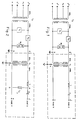
- In the embodiment of fig 2, showing a coupling device for a secondary cabin with discharger on the MV side, in the medium voltage (MV) section, a discharger or spark gap SC₂ is inserted in parallel between parts A and B on phase lines X and Y between the inductor and the coupling capacitor.
- With this solution, providing a discharger fitted between points A and B,that is across the isolating transformer and the tuning inductor fitted in series, the overvoltages from phases X and Y are limited; it is therefore avoided that said overvoltages will involve these two components as a result of which the dimensions of isolating transformer T and inductor L can be drastically reduced.
- The only component that will have to withstand the overvoltage is the capacitor. In this way, both transformer T₁ and inductor L can be isolated hence sized for a much lower voltage, thereby consenting a considerable saving in material, in addition, to reducing costs and all overall dimensions as well as improving operation at the signal frequency.
- In the second embodiment of fig 3 showing a coupling device for a secondary cabin with discharger on the MV side, a second discharger SC₃ is provided in parallel with inductor L in addition to a discharger SC₂ fitted in parallel between points A and B on phase lines X and Y between the tuning inductor and the isolating transformer.
- The third form of embodiment of this invention relating to a coupling device for secondary cabins whith balanced circuits and MV discharger, as shown in fig 4, is similar to that of fig 2 and contemplates a specularity between the line of phase X and that of phase Y i.e. on the phase Y line are provided an inductor L₂ and a capacitor C₂ equal to inductor L₁ and to capacitor C₁ inserted in the line of phase X between which pairs a discharger SC₂ is fitted.
- The fourth embodiment of this invention relating to a coupling device for secondary cabins with balanced inductance and MV dischargers as illustrated in fig 5 contenplates a specularity between lines of phase X and that of phaseY i.e. on the line of phase Y are fitted an inductor L₂ a discharger SC₄ inserted in parallel equal to inductor L₁ and discharger SC₃ inserted on the line of phase X, the two inductor/discharger pairs being fitted between the connecting points of the primary winding of the isolating transformer and the respective coupling capacitors C₁ - C₂. It is possible also to apply a single coupling capacitor C in the line of one phase.
- The fifth embodiment illustrated in fig 6, as a variant of fig 2, shows a coupling device for secondary cabins with discharger on the MV side, in the medium voltage (MV) section,in which, a discharger SC₂ in parallel between points A and B on phase lines X and Y, is fitted ahead of the coupling capacitor. In this variant, the tuning inductance L is incorporated in that of isolating transformer T₁ exploiting the flux dispersed in the magnetic circuit.
Claims (5)
- Phase - phase coupling device for medium voltage (MV) networks comprising an isolating transformer, a branch of the primary winding of which is connected to at least one inductor in series with a coupling capacitor, characterized in that at least one discharger connecting the two phases is provided between the inductor and the coupling condenser (fig 2).
- Phase - phase coupling device according to claim 1, characterized in that a discharger is connected in parallel to the inductor whilst another discharger is connected to the primary winding of the isolating transformer (fig 3).
- Phase - phase coupling device according to claim 1, characterized in that each one of the lines of the two phases comprises an inductor in series and a coupling capacitor, a discharger being inserted between the connection points of the inductor/capacitor pairs (fig 4).
- Phase - phase coupling device according to claim 3 characterized in that one discharger is fitted in parallel to the primary of said isolating transformer, whilst another two are connected in parallel with the pair of inductors (fig 5).
- Phase - phase coupling device according to claim 1, characterized in that the tuning inductance is incorporated in that of the transformer, exploiting the flux dispersed in the magnetic circuit (fig 6).
Applications Claiming Priority (2)
| Application Number | Priority Date | Filing Date | Title |
|---|---|---|---|
| IT2218590 | 1990-11-26 | ||
| IT02218590A IT1244028B (en) | 1990-11-26 | 1990-11-26 | PHASE-PHASE COUPLING DEVICE FOR MEDIUM VOLTAGE NETWORKS. |
Publications (2)
| Publication Number | Publication Date |
|---|---|
| EP0487812A2 true EP0487812A2 (en) | 1992-06-03 |
| EP0487812A3 EP0487812A3 (en) | 1993-03-03 |
Family
ID=11192755
Family Applications (1)
| Application Number | Title | Priority Date | Filing Date |
|---|---|---|---|
| EP19910102246 Withdrawn EP0487812A3 (en) | 1990-11-26 | 1991-02-18 | Phase - phase coupling device for medium voltage networks |
Country Status (2)
| Country | Link |
|---|---|
| EP (1) | EP0487812A3 (en) |
| IT (1) | IT1244028B (en) |
Cited By (1)
| Publication number | Priority date | Publication date | Assignee | Title |
|---|---|---|---|---|
| WO2001059903A1 (en) * | 2000-02-09 | 2001-08-16 | E.O.S. S.A. | Secondary circuit in a high or medium voltage network |
Family Cites Families (2)
| Publication number | Priority date | Publication date | Assignee | Title |
|---|---|---|---|---|
| GB318557A (en) * | 1928-03-03 | 1929-09-03 | Telefunken Gmbh | Improvements in or relating to high frequency telephone systems |
| US4766414A (en) * | 1986-06-17 | 1988-08-23 | Westinghouse Electric Corp. | Power line communication interference preventing circuit |
-
1990
- 1990-11-26 IT IT02218590A patent/IT1244028B/en active IP Right Grant
-
1991
- 1991-02-18 EP EP19910102246 patent/EP0487812A3/en not_active Withdrawn
Cited By (1)
| Publication number | Priority date | Publication date | Assignee | Title |
|---|---|---|---|---|
| WO2001059903A1 (en) * | 2000-02-09 | 2001-08-16 | E.O.S. S.A. | Secondary circuit in a high or medium voltage network |
Also Published As
| Publication number | Publication date |
|---|---|
| EP0487812A3 (en) | 1993-03-03 |
| IT1244028B (en) | 1994-06-28 |
| IT9022185A0 (en) | 1990-11-26 |
| IT9022185A1 (en) | 1992-05-27 |
Similar Documents
| Publication | Publication Date | Title |
|---|---|---|
| US4890089A (en) | Distribution of line carrier communications | |
| US4004110A (en) | Power supply for power line carrier communication systems | |
| US4012733A (en) | Distribution power line communication system including a messenger wire communications link | |
| US4473816A (en) | Communications signal bypass around power line transformer | |
| US4481501A (en) | Transformer arrangement for coupling a communication signal to a three-phase power line | |
| US4254402A (en) | Transformer arrangement for coupling a communication signal to a three-phase power line | |
| US4473817A (en) | Coupling power line communications signals around distribution transformers | |
| US4188619A (en) | Transformer arrangement for coupling a communication signal to a three-phase power line | |
| EP1883866B1 (en) | Power line communications interface and surge protector | |
| US20040100230A1 (en) | Device and a method for control of power flow in a transmission line | |
| GB2094596A (en) | Power line communication over ground and neutral conductors of plural residential branch circuit | |
| JPH0225296B2 (en) | ||
| US4008467A (en) | Power line carrier communication system having efficient carrier signal coupling of distribution secondary lines | |
| US7317301B2 (en) | Auxiliary power supply | |
| US4458236A (en) | Communications signal coupling around wye/delta power transformation | |
| US4126793A (en) | Circuit arrangement for a remote control receiver | |
| US4066912A (en) | Coupling arrangement for power line carrier systems | |
| US20060082323A1 (en) | Decoupling circuits | |
| US5047890A (en) | Differential current protection circuits | |
| US7154382B2 (en) | Arrangement of inductive couplers for data communication | |
| CN106856323B (en) | Protective device for protecting transformers from geomagnetically induced currents | |
| Chen | Comparison of Scott and Leblanc transformers for supplying unbalanced electric railway demands | |
| EP0487812A2 (en) | Phase - phase coupling device for medium voltage networks | |
| US4194128A (en) | Ripple control systems | |
| WO1995006761A1 (en) | Device for compensation of an alternating voltage which occurs between a medium and a metallic pipeline disposed in the medium |
Legal Events
| Date | Code | Title | Description |
|---|---|---|---|
| PUAI | Public reference made under article 153(3) epc to a published international application that has entered the european phase |
Free format text: ORIGINAL CODE: 0009012 |
|
| AK | Designated contracting states |
Kind code of ref document: A2 Designated state(s): AT BE CH DE DK ES FR GB IT LI NL SE |
|
| ITCL | It: translation for ep claims filed |
Representative=s name: ING. C. GREGORJ S.P.A. |
|
| PUAL | Search report despatched |
Free format text: ORIGINAL CODE: 0009013 |
|
| AK | Designated contracting states |
Kind code of ref document: A3 Designated state(s): AT BE CH DE DK ES FR GB IT LI NL SE |
|
| STAA | Information on the status of an ep patent application or granted ep patent |
Free format text: STATUS: THE APPLICATION IS DEEMED TO BE WITHDRAWN |
|
| 18D | Application deemed to be withdrawn |
Effective date: 19930904 |