EP0487753A1 - Module cover for air bag device - Google Patents
Module cover for air bag device Download PDFInfo
- Publication number
- EP0487753A1 EP0487753A1 EP91911366A EP91911366A EP0487753A1 EP 0487753 A1 EP0487753 A1 EP 0487753A1 EP 91911366 A EP91911366 A EP 91911366A EP 91911366 A EP91911366 A EP 91911366A EP 0487753 A1 EP0487753 A1 EP 0487753A1
- Authority
- EP
- European Patent Office
- Prior art keywords
- projection
- modular cover
- tear line
- junction
- air bag
- Prior art date
- Legal status (The legal status is an assumption and is not a legal conclusion. Google has not performed a legal analysis and makes no representation as to the accuracy of the status listed.)
- Granted
Links
Images

Classifications
-
- B—PERFORMING OPERATIONS; TRANSPORTING
- B60—VEHICLES IN GENERAL
- B60R—VEHICLES, VEHICLE FITTINGS, OR VEHICLE PARTS, NOT OTHERWISE PROVIDED FOR
- B60R21/00—Arrangements or fittings on vehicles for protecting or preventing injuries to occupants or pedestrians in case of accidents or other traffic risks
- B60R21/02—Occupant safety arrangements or fittings, e.g. crash pads
- B60R21/16—Inflatable occupant restraints or confinements designed to inflate upon impact or impending impact, e.g. air bags
-
- B—PERFORMING OPERATIONS; TRANSPORTING
- B60—VEHICLES IN GENERAL
- B60R—VEHICLES, VEHICLE FITTINGS, OR VEHICLE PARTS, NOT OTHERWISE PROVIDED FOR
- B60R21/00—Arrangements or fittings on vehicles for protecting or preventing injuries to occupants or pedestrians in case of accidents or other traffic risks
- B60R21/02—Occupant safety arrangements or fittings, e.g. crash pads
- B60R21/16—Inflatable occupant restraints or confinements designed to inflate upon impact or impending impact, e.g. air bags
- B60R21/20—Arrangements for storing inflatable members in their non-use or deflated condition; Arrangement or mounting of air bag modules or components
- B60R21/215—Arrangements for storing inflatable members in their non-use or deflated condition; Arrangement or mounting of air bag modules or components characterised by the covers for the inflatable member
- B60R21/2165—Arrangements for storing inflatable members in their non-use or deflated condition; Arrangement or mounting of air bag modules or components characterised by the covers for the inflatable member characterised by a tear line for defining a deployment opening
- B60R21/21656—Steering wheel covers or similar cup-shaped covers
-
- B—PERFORMING OPERATIONS; TRANSPORTING
- B29—WORKING OF PLASTICS; WORKING OF SUBSTANCES IN A PLASTIC STATE IN GENERAL
- B29C—SHAPING OR JOINING OF PLASTICS; SHAPING OF MATERIAL IN A PLASTIC STATE, NOT OTHERWISE PROVIDED FOR; AFTER-TREATMENT OF THE SHAPED PRODUCTS, e.g. REPAIRING
- B29C59/00—Surface shaping of articles, e.g. embossing; Apparatus therefor
- B29C59/007—Forming single grooves or ribs, e.g. tear lines, weak spots
-
- B—PERFORMING OPERATIONS; TRANSPORTING
- B29—WORKING OF PLASTICS; WORKING OF SUBSTANCES IN A PLASTIC STATE IN GENERAL
- B29L—INDEXING SCHEME ASSOCIATED WITH SUBCLASS B29C, RELATING TO PARTICULAR ARTICLES
- B29L2031/00—Other particular articles
- B29L2031/30—Vehicles, e.g. ships or aircraft, or body parts thereof
- B29L2031/3005—Body finishings
- B29L2031/3038—Air bag covers
Definitions
- the present invention relates to a modular cover for containing an air bag which is deployed and inflated when impact or deformation is sensed during a crash.
- a modular cover includes a rigid inner layer 11, and a flexible outer layer 12.
- a tear line 13 is formed to permit the modular cover to rupture when an air bag is deployed.
- This modular cover is typically made by a two-color molding process in which two resins are separately introduced into molds.
- a molded modular cover may have a shrunk surface (sinkmarks) during curing of resins. This presents the following problems.
- Fig. 4 is an enlarged view of a portion indicated as IV in Fig. 3.
- the outer layer 12 has a surface 12a in which recesses A are formed along a groove 13. This impairs the esthetic appearance of the modular cover.
- a modular cover for an air bag assembly comprising a rigid inner layer and a flexible outer layer.
- the modular cover is ruptured along a tear line.
- the tear line includes a projection raised from the junction of the inner layer with the outer layer, and a groove formed in the inner surface of the modular cover.
- the projection is substantially trapezoidal in transverse section and has inclined surfaces. The angle formed by the inclined surface and the junction adjacent to the projection is no more than 30 ° .
- a modular cover for an air bag assembly comprising a rigid inner layer and a flexible outer layer.
- the modular cover is ruptured along a tear line.
- the tear line includes a projection raised from the junction of the inner layer with the outer layer, and a groove formed in the inner surface of the modular cover.
- the projection is substantially ellipsoidal in transverse section and has a top. The angle formed by the junction and a line extending between the top of the projection and a point at which the projection merges with the junction is no more than 30 ° .
- the junction between the inner layer and the outer layer adjacent to the tear line is inclined at a small angle or is curved. This reduces the effect of sinkmarks formed adjacent to the tear line. The resulting recesses in the outer layer are not noticeable as such.
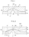
- Figs. 1 and 2 are enlarged sectional views of tear lines formed in modular covers for an air bag assembly according to embodiments of the present invention.
- a modular cover 1 for an air bag assembly includes a rigid inner layer 1A, and a flexible outer layer 1B.
- a score line 2 includes a projection 1C, a groove 2A, and a slit 2B.
- the projection 1C is raised from the junction 20 of the inner layer 1A with the outer layer 1B and has a substantially trapezoidal section.
- the projection 1C has a top 1D joined to the inner surface of the modular cover via the slit 2B and the groove 2A of a V-shaped section.
- the projection 1C has inclined surfaces 1E.
- an angle ⁇ 1 formed by the inclined surface 1E and the junction 20 adjacent to the projection 1C is no more than 30 ° .
- a modular cover 100 is identical in structure to the modular cover shown in Fig. 1, except that the projection 1C of the inner layer 1A has an ellipsoidal section.
- Like reference numerals indicate like or corresponding parts.
- P1 is a point at which a projection surface 1F merges with the junction 20 adjacent to the projection 1C.
- a line 21 extends between this point P1 and a top P2 of the projection.
- An angle ⁇ 2 formed by the line 21 and the junction is no more than 30 ° .
- sinkmarks are formed during curing of the outer layer, but the resultant recesses may not gather around the tear line 2 and have greater widths (in a direction perpendicular to the tear line 2). Also, these recesses are shallow and thus, unnoticeable.
- the angle ⁇ 1 or the angle ⁇ 2 is preferably in the range of between 5 ° and 20 ° .
- the modular covers shown in Figs. 1 and 2 are illustrative only. The present invention is not limited to those shown in the drawing.
- the tear line may have other sections or shapes.
- the projection has an arcuate surface 1F, but may have a semiellipsoidal or other round surface. Additionally, the slit 2B may not terminate at the outer layer 1B.
- the modular cover of the present invention barely suffers from recesses which may occur due to sinkmarks during curing of the outer layer and can thus have a flat outer surface and provide good esthetic appearance.
Landscapes
- Engineering & Computer Science (AREA)
- Mechanical Engineering (AREA)
- Air Bags (AREA)
- Moulds For Moulding Plastics Or The Like (AREA)
- Injection Moulding Of Plastics Or The Like (AREA)
- Buffer Packaging (AREA)
Abstract
Description
- The present invention relates to a modular cover for containing an air bag which is deployed and inflated when impact or deformation is sensed during a crash.
- As shown in Fig. 3, a modular cover includes a rigid
inner layer 11, and a flexibleouter layer 12. Atear line 13 is formed to permit the modular cover to rupture when an air bag is deployed. This modular cover is typically made by a two-color molding process in which two resins are separately introduced into molds. - When a two-color molding process is used to mold a modular cover composed of two layers, inner and outer layers as shown in Fig. 3, a molded modular cover may have a shrunk surface (sinkmarks) during curing of resins. This presents the following problems.
- When a modular cover as shown in Fig. 3 is made by a two-color molding process, sinkmarks (surface contraction) may appear when the
outer layer 12 is molded, as shown in Fig. 4. Fig. 4 is an enlarged view of a portion indicated as IV in Fig. 3. Theouter layer 12 has a surface 12a in which recesses A are formed along agroove 13. This impairs the esthetic appearance of the modular cover. - It is an object of the present invention to overcome the problems encountered in the prior art, and to provide a modular cover for an air bag assembly, which is free from recesses which may, otherwise, be formed due to surface contraction while the outer layer of the modular cover is being molded.
- According to the present invention, there is provided a modular cover for an air bag assembly comprising a rigid inner layer and a flexible outer layer. The modular cover is ruptured along a tear line. The tear line includes a projection raised from the junction of the inner layer with the outer layer, and a groove formed in the inner surface of the modular cover. The projection is substantially trapezoidal in transverse section and has inclined surfaces. The angle formed by the inclined surface and the junction adjacent to the projection is no more than 30 ° .
- According to another aspect of the present invention, there is provided a modular cover for an air bag assembly comprising a rigid inner layer and a flexible outer layer. The modular cover is ruptured along a tear line. The tear line includes a projection raised from the junction of the inner layer with the outer layer, and a groove formed in the inner surface of the modular cover. The projection is substantially ellipsoidal in transverse section and has a top. The angle formed by the junction and a line extending between the top of the projection and a point at which the projection merges with the junction is no more than 30 ° .
- In the modular cover of the present invention, the junction between the inner layer and the outer layer adjacent to the tear line is inclined at a small angle or is curved. This reduces the effect of sinkmarks formed adjacent to the tear line. The resulting recesses in the outer layer are not noticeable as such.
-
- Fig. 1 is an enlarged sectional view showing the principal part of a modular cover for an air bag assembly made according to one embodiment of the present invention;
- Fig. 2 is an enlarged sectional view showing an alternative embodiment;
- Fig. 3 is a sectional view of the prior art; and
- Fig. 4 is an enlarged view of a portion indicated as at IV in Fig. 3.
- The present invention will now be described by way of example with reference to the drawings.
- Figs. 1 and 2 are enlarged sectional views of tear lines formed in modular covers for an air bag assembly according to embodiments of the present invention.
- Referring to Fig. 1, a
modular cover 1 for an air bag assembly includes a rigid inner layer 1A, and a flexibleouter layer 1B. Ascore line 2 includes aprojection 1C, agroove 2A, and a slit 2B. Specifically, theprojection 1C is raised from thejunction 20 of the inner layer 1A with theouter layer 1B and has a substantially trapezoidal section. Theprojection 1C has atop 1D joined to the inner surface of the modular cover via the slit 2B and thegroove 2A of a V-shaped section. - The
projection 1C hasinclined surfaces 1E. In this invention, anangle ϑ ₁ formed by theinclined surface 1E and thejunction 20 adjacent to theprojection 1C is no more than 30 ° . - In Fig. 2, a
modular cover 100 is identical in structure to the modular cover shown in Fig. 1, except that theprojection 1C of the inner layer 1A has an ellipsoidal section. Like reference numerals indicate like or corresponding parts. - In Fig. 2, P₁ is a point at which a
projection surface 1F merges with thejunction 20 adjacent to theprojection 1C. Aline 21 extends between this point P₁ and a top P₂ of the projection. Anangle ϑ ₂ formed by theline 21 and the junction is no more than 30 ° . - By forming a projection so that the
angle ϑ ₁ or theangle ϑ ₂ is no more than 30 ° , sinkmarks are formed during curing of the outer layer, but the resultant recesses may not gather around thetear line 2 and have greater widths (in a direction perpendicular to the tear line 2). Also, these recesses are shallow and thus, unnoticeable. - In the present invention, the
angle ϑ ₁ or theangle ϑ ₂ is preferably in the range of between 5 ° and 20 ° . - The modular covers shown in Figs. 1 and 2 are illustrative only. The present invention is not limited to those shown in the drawing. The tear line may have other sections or shapes. In Fig. 2, the projection has an
arcuate surface 1F, but may have a semiellipsoidal or other round surface. Additionally, the slit 2B may not terminate at theouter layer 1B. - As described in detail, the modular cover of the present invention barely suffers from recesses which may occur due to sinkmarks during curing of the outer layer and can thus have a flat outer surface and provide good esthetic appearance.
Claims (6)
- A modular cover for an air bag assembly, comprising a rigid inner layer and a flexible outer layer, said modular cover being ruptured along a tear line,
said tear line including a projection raised from a junction of said inner layer with said outer layer, and a groove formed in the inner surface of the modular cover,
said projection being substantially trapezoidal in transverse section and having inclined surfaces, an angle formed by said inclined surface and said junction adjacent to the projection being no more than 30 ° . - The modular cover of claim 1, wherein said angle is in the range of between 5 ° and 20 ° .
- The modular cover of claim 1, wherein said groove has a V-shaped section.
- A modular cover for an air bag assembly, comprising a rigid inner layer and a flexible outer layer, said modular cover being ruptured along a tear line,
said tear line including a projection raised from a junction of said inner layer with the outer layer, and a groove formed in the inner surface of the modular cover,
said projection being convexly curved in transverse section and having a top, an angle formed by said junction and a line extending between said top and a point at which said projection merges with said junction being no more than 30 ° . - The modular cover of claim 4, wherein said angle is in the range of between 5 ° and 20 ° .
- The modular cover of claim 4, wherein said groove has a V-shaped section.
Applications Claiming Priority (3)
| Application Number | Priority Date | Filing Date | Title |
|---|---|---|---|
| JP2161798A JP2956137B2 (en) | 1990-06-20 | 1990-06-20 | Module cover for airbag device |
| JP161798/90 | 1990-06-20 | ||
| PCT/JP1991/000821 WO1991019630A1 (en) | 1990-06-20 | 1991-06-19 | Module cover for air bag device |
Publications (3)
| Publication Number | Publication Date |
|---|---|
| EP0487753A1 true EP0487753A1 (en) | 1992-06-03 |
| EP0487753A4 EP0487753A4 (en) | 1993-02-03 |
| EP0487753B1 EP0487753B1 (en) | 1994-11-09 |
Family
ID=15742116
Family Applications (1)
| Application Number | Title | Priority Date | Filing Date |
|---|---|---|---|
| EP91911366A Expired - Lifetime EP0487753B1 (en) | 1990-06-20 | 1991-06-19 | Module cover for air bag device |
Country Status (7)
| Country | Link |
|---|---|
| EP (1) | EP0487753B1 (en) |
| JP (1) | JP2956137B2 (en) |
| KR (1) | KR920000546A (en) |
| CA (1) | CA2064096A1 (en) |
| DE (1) | DE69105096T2 (en) |
| GB (1) | GB2250244B (en) |
| WO (1) | WO1991019630A1 (en) |
Cited By (9)
| Publication number | Priority date | Publication date | Assignee | Title |
|---|---|---|---|---|
| DE4135168A1 (en) * | 1990-10-26 | 1992-04-30 | Takata Corp | COVER, IN PARTICULAR MODULAR COVER, FOR AN AIR BAG |
| EP0590779A1 (en) * | 1992-09-28 | 1994-04-06 | Davidson Textron Inc. | Airbag cover and apparatus for producing an invisible tear seam therein |
| EP0588176A3 (en) * | 1992-09-16 | 1995-08-02 | Toyoda Gosei Kk | Cover for an airbag. |
| EP0741062A3 (en) * | 1995-05-03 | 1996-12-11 | Eldra Kunststofftechnik Gmbh | |
| EP0844143A1 (en) * | 1996-11-21 | 1998-05-27 | Adam Opel Ag | Casing with a receiving cavity for foldable and inflatable airbag |
| WO1998049033A1 (en) * | 1997-04-28 | 1998-11-05 | Petri Ag | Airbag covering cap comprising a support layer and a cover layer of different elasticities |
| EP0930202A3 (en) * | 1998-01-17 | 2002-08-07 | Adam Opel Ag | Interior trim panel, in particular for a motor vehicle |
| DE102007060584A1 (en) * | 2007-12-13 | 2009-06-25 | Johnson Controls Interiors Gmbh & Co. Kg | Decorative skin for an airbag cover |
| EP3708437A1 (en) * | 2019-03-12 | 2020-09-16 | Toyota Jidosha Kabushiki Kaisha | Airbag apparatus |
Families Citing this family (6)
| Publication number | Priority date | Publication date | Assignee | Title |
|---|---|---|---|---|
| JPH05279481A (en) * | 1992-03-31 | 1993-10-26 | Toray Dow Corning Silicone Co Ltd | Fluorosilicone block copolymer and method for producing the same |
| GB2276354B (en) * | 1993-03-22 | 1996-01-03 | Klippan Autoliv Snc | Improvements in or relating to a cover for an air-bag |
| DE102007011842A1 (en) | 2007-03-12 | 2008-09-18 | GM Global Technology Operations, Inc., Detroit | Non-visible airbag door, apparatus and method of making the same |
| JP6482340B2 (en) * | 2015-03-20 | 2019-03-13 | 株式会社イノアックコーポレーション | Vehicle interior parts |
| CN108263330A (en) * | 2018-03-29 | 2018-07-10 | 江铃汽车股份有限公司 | It can remove the air bag cover plate of tearing mark |
| EP4598780A1 (en) * | 2022-10-06 | 2025-08-13 | Yanfeng International Automotive Technology Co., Ltd | Component for vehicle interior |
Family Cites Families (4)
| Publication number | Priority date | Publication date | Assignee | Title |
|---|---|---|---|---|
| JPH0790743B2 (en) * | 1987-10-21 | 1995-10-04 | タカタ株式会社 | Airbag cover and method of manufacturing the same |
| JPH0621935B2 (en) * | 1988-06-13 | 1994-03-23 | 三菱製紙株式会社 | Method for producing photographic resin-coated paper |
| JPH0694266B2 (en) * | 1989-02-20 | 1994-11-24 | タカタ株式会社 | Airbag storage cover |
| JPH10202550A (en) * | 1997-01-16 | 1998-08-04 | Mitsubishi Heavy Ind Ltd | Bolt fastening tool with axial force measuring device |
-
1990
- 1990-06-20 JP JP2161798A patent/JP2956137B2/en not_active Expired - Fee Related
-
1991
- 1991-06-18 KR KR1019910010097A patent/KR920000546A/en not_active Withdrawn
- 1991-06-19 DE DE69105096T patent/DE69105096T2/en not_active Expired - Fee Related
- 1991-06-19 CA CA002064096A patent/CA2064096A1/en not_active Abandoned
- 1991-06-19 WO PCT/JP1991/000821 patent/WO1991019630A1/en not_active Ceased
- 1991-06-19 EP EP91911366A patent/EP0487753B1/en not_active Expired - Lifetime
- 1991-06-19 GB GB9201548A patent/GB2250244B/en not_active Expired - Fee Related
Cited By (12)
| Publication number | Priority date | Publication date | Assignee | Title |
|---|---|---|---|---|
| DE4135168A1 (en) * | 1990-10-26 | 1992-04-30 | Takata Corp | COVER, IN PARTICULAR MODULAR COVER, FOR AN AIR BAG |
| EP0588176A3 (en) * | 1992-09-16 | 1995-08-02 | Toyoda Gosei Kk | Cover for an airbag. |
| EP0590779A1 (en) * | 1992-09-28 | 1994-04-06 | Davidson Textron Inc. | Airbag cover and apparatus for producing an invisible tear seam therein |
| EP0741062A3 (en) * | 1995-05-03 | 1996-12-11 | Eldra Kunststofftechnik Gmbh | |
| EP0844143A1 (en) * | 1996-11-21 | 1998-05-27 | Adam Opel Ag | Casing with a receiving cavity for foldable and inflatable airbag |
| WO1998049033A1 (en) * | 1997-04-28 | 1998-11-05 | Petri Ag | Airbag covering cap comprising a support layer and a cover layer of different elasticities |
| US6505850B2 (en) | 1997-04-28 | 2003-01-14 | Takata-Petri Ag | Airbag covering cap comprising a support layer and a cover layer of different elasticities |
| EP0930202A3 (en) * | 1998-01-17 | 2002-08-07 | Adam Opel Ag | Interior trim panel, in particular for a motor vehicle |
| DE102007060584A1 (en) * | 2007-12-13 | 2009-06-25 | Johnson Controls Interiors Gmbh & Co. Kg | Decorative skin for an airbag cover |
| EP3708437A1 (en) * | 2019-03-12 | 2020-09-16 | Toyota Jidosha Kabushiki Kaisha | Airbag apparatus |
| CN111688625A (en) * | 2019-03-12 | 2020-09-22 | 丰田自动车株式会社 | Airbag device |
| US11225217B2 (en) | 2019-03-12 | 2022-01-18 | Toyota Jidosha Kabushiki Kaisha | Airbag apparatus |
Also Published As
| Publication number | Publication date |
|---|---|
| JPH0450056A (en) | 1992-02-19 |
| CA2064096A1 (en) | 1991-12-21 |
| GB2250244A (en) | 1992-06-03 |
| GB9201548D0 (en) | 1992-03-11 |
| EP0487753B1 (en) | 1994-11-09 |
| JP2956137B2 (en) | 1999-10-04 |
| GB2250244B (en) | 1994-06-15 |
| DE69105096D1 (en) | 1994-12-15 |
| KR920000546A (en) | 1992-01-29 |
| WO1991019630A1 (en) | 1991-12-26 |
| DE69105096T2 (en) | 1995-03-23 |
| EP0487753A4 (en) | 1993-02-03 |
Similar Documents
| Publication | Publication Date | Title |
|---|---|---|
| EP0487753B1 (en) | Module cover for air bag device | |
| US5172931A (en) | Modular cover for an air bag | |
| US5669829A (en) | Golf club head | |
| KR100396472B1 (en) | Air Bag Assembly | |
| US5292150A (en) | Cover of air bag device | |
| CA2006284A1 (en) | Cover for a vehicle air bag | |
| WO2000003874A1 (en) | Decorative material | |
| WO1994006701A1 (en) | Security seal | |
| CA2201142A1 (en) | Ball joint link and method of producing same | |
| US5172932A (en) | Air bag device | |
| CA2030619A1 (en) | Retainer for air bag system | |
| JP2647172B2 (en) | Protective chip for tearing clothing frame | |
| US5433473A (en) | Pad mounting structure for air bag device | |
| GB2262488A (en) | A cover for an air bag. | |
| JPH0739143B2 (en) | Joint structure of hollow synthetic resin | |
| US5334340A (en) | Method of producing a modular cover for an air bag assembly | |
| US5431434A (en) | Modular cover for air bag system | |
| JP2533251Y2 (en) | Resin window panel | |
| EP0487752B1 (en) | Method of forming module cover of air bag device | |
| EP0487746A1 (en) | Method of forming module cover of air bag device | |
| JP2577016Y2 (en) | Outside molding structure of vehicle | |
| EP1102265A3 (en) | Magnetic tape cassette, window member and resin molding product | |
| JPH09197072A (en) | Exterior cover and method of forming the same | |
| JPS62211111A (en) | Insert molding process for opening portion of molded product | |
| JPH06286552A (en) | Module cover of air bag device |
Legal Events
| Date | Code | Title | Description |
|---|---|---|---|
| PUAI | Public reference made under article 153(3) epc to a published international application that has entered the european phase |
Free format text: ORIGINAL CODE: 0009012 |
|
| 17P | Request for examination filed |
Effective date: 19920127 |
|
| AK | Designated contracting states |
Kind code of ref document: A1 Designated state(s): DE FR |
|
| A4 | Supplementary search report drawn up and despatched | ||
| AK | Designated contracting states |
Kind code of ref document: A4 Designated state(s): DE FR |
|
| 17Q | First examination report despatched |
Effective date: 19940125 |
|
| GRAA | (expected) grant |
Free format text: ORIGINAL CODE: 0009210 |
|
| AK | Designated contracting states |
Kind code of ref document: B1 Designated state(s): DE FR |
|
| REF | Corresponds to: |
Ref document number: 69105096 Country of ref document: DE Date of ref document: 19941215 |
|
| ET | Fr: translation filed | ||
| PLBE | No opposition filed within time limit |
Free format text: ORIGINAL CODE: 0009261 |
|
| STAA | Information on the status of an ep patent application or granted ep patent |
Free format text: STATUS: NO OPPOSITION FILED WITHIN TIME LIMIT |
|
| 26N | No opposition filed | ||
| PGFP | Annual fee paid to national office [announced via postgrant information from national office to epo] |
Ref country code: FR Payment date: 19990610 Year of fee payment: 9 |
|
| PG25 | Lapsed in a contracting state [announced via postgrant information from national office to epo] |
Ref country code: FR Free format text: LAPSE BECAUSE OF NON-PAYMENT OF DUE FEES Effective date: 20010228 |
|
| REG | Reference to a national code |
Ref country code: FR Ref legal event code: ST |
|
| PGFP | Annual fee paid to national office [announced via postgrant information from national office to epo] |
Ref country code: DE Payment date: 20080626 Year of fee payment: 18 |
|
| PG25 | Lapsed in a contracting state [announced via postgrant information from national office to epo] |
Ref country code: DE Free format text: LAPSE BECAUSE OF NON-PAYMENT OF DUE FEES Effective date: 20100101 |