EP0486972A2 - Image-forming apparatus - Google Patents
Image-forming apparatus Download PDFInfo
- Publication number
- EP0486972A2 EP0486972A2 EP91119558A EP91119558A EP0486972A2 EP 0486972 A2 EP0486972 A2 EP 0486972A2 EP 91119558 A EP91119558 A EP 91119558A EP 91119558 A EP91119558 A EP 91119558A EP 0486972 A2 EP0486972 A2 EP 0486972A2
- Authority
- EP
- European Patent Office
- Prior art keywords
- paper
- tray
- image
- discharging
- stocking
- Prior art date
- Legal status (The legal status is an assumption and is not a legal conclusion. Google has not performed a legal analysis and makes no representation as to the accuracy of the status listed.)
- Granted
Links
Images


Classifications
-
- G—PHYSICS
- G03—PHOTOGRAPHY; CINEMATOGRAPHY; ANALOGOUS TECHNIQUES USING WAVES OTHER THAN OPTICAL WAVES; ELECTROGRAPHY; HOLOGRAPHY
- G03G—ELECTROGRAPHY; ELECTROPHOTOGRAPHY; MAGNETOGRAPHY
- G03G15/00—Apparatus for electrographic processes using a charge pattern
- G03G15/65—Apparatus which relate to the handling of copy material
- G03G15/6552—Means for discharging uncollated sheet copy material, e.g. discharging rollers, exit trays
-
- B—PERFORMING OPERATIONS; TRANSPORTING
- B65—CONVEYING; PACKING; STORING; HANDLING THIN OR FILAMENTARY MATERIAL
- B65H—HANDLING THIN OR FILAMENTARY MATERIAL, e.g. SHEETS, WEBS, CABLES
- B65H31/00—Pile receivers
- B65H31/02—Pile receivers with stationary end support against which pile accumulates
-
- B—PERFORMING OPERATIONS; TRANSPORTING
- B65—CONVEYING; PACKING; STORING; HANDLING THIN OR FILAMENTARY MATERIAL
- B65H—HANDLING THIN OR FILAMENTARY MATERIAL, e.g. SHEETS, WEBS, CABLES
- B65H85/00—Recirculating articles, i.e. feeding each article to, and delivering it from, the same machine work-station more than once
-
- G—PHYSICS
- G03—PHOTOGRAPHY; CINEMATOGRAPHY; ANALOGOUS TECHNIQUES USING WAVES OTHER THAN OPTICAL WAVES; ELECTROGRAPHY; HOLOGRAPHY
- G03G—ELECTROGRAPHY; ELECTROPHOTOGRAPHY; MAGNETOGRAPHY
- G03G15/00—Apparatus for electrographic processes using a charge pattern
- G03G15/22—Apparatus for electrographic processes using a charge pattern involving the combination of more than one step according to groups G03G13/02 - G03G13/20
- G03G15/23—Apparatus for electrographic processes using a charge pattern involving the combination of more than one step according to groups G03G13/02 - G03G13/20 specially adapted for copying both sides of an original or for copying on both sides of a recording or image-receiving material
- G03G15/231—Arrangements for copying on both sides of a recording or image-receiving material
- G03G15/232—Arrangements for copying on both sides of a recording or image-receiving material using a single reusable electrographic recording member
- G03G15/234—Arrangements for copying on both sides of a recording or image-receiving material using a single reusable electrographic recording member by inverting and refeeding the image receiving material with an image on one face to the recording member to transfer a second image on its second face, e.g. by using a duplex tray; Details of duplex trays or inverters
-
- G—PHYSICS
- G03—PHOTOGRAPHY; CINEMATOGRAPHY; ANALOGOUS TECHNIQUES USING WAVES OTHER THAN OPTICAL WAVES; ELECTROGRAPHY; HOLOGRAPHY
- G03G—ELECTROGRAPHY; ELECTROPHOTOGRAPHY; MAGNETOGRAPHY
- G03G15/00—Apparatus for electrographic processes using a charge pattern
- G03G15/65—Apparatus which relate to the handling of copy material
- G03G15/6555—Handling of sheet copy material taking place in a specific part of the copy material feeding path
- G03G15/6573—Feeding path after the fixing point and up to the discharge tray or the finisher, e.g. special treatment of copy material to compensate for effects from the fixing
-
- B—PERFORMING OPERATIONS; TRANSPORTING
- B65—CONVEYING; PACKING; STORING; HANDLING THIN OR FILAMENTARY MATERIAL
- B65H—HANDLING THIN OR FILAMENTARY MATERIAL, e.g. SHEETS, WEBS, CABLES
- B65H2301/00—Handling processes for sheets or webs
- B65H2301/40—Type of handling process
- B65H2301/42—Piling, depiling, handling piles
- B65H2301/421—Forming a pile
- B65H2301/4212—Forming a pile of articles substantially horizontal
-
- B—PERFORMING OPERATIONS; TRANSPORTING
- B65—CONVEYING; PACKING; STORING; HANDLING THIN OR FILAMENTARY MATERIAL
- B65H—HANDLING THIN OR FILAMENTARY MATERIAL, e.g. SHEETS, WEBS, CABLES
- B65H2511/00—Dimensions; Position; Numbers; Identification; Occurrences
- B65H2511/10—Size; Dimensions
-
- B—PERFORMING OPERATIONS; TRANSPORTING
- B65—CONVEYING; PACKING; STORING; HANDLING THIN OR FILAMENTARY MATERIAL
- B65H—HANDLING THIN OR FILAMENTARY MATERIAL, e.g. SHEETS, WEBS, CABLES
- B65H2513/00—Dynamic entities; Timing aspects
- B65H2513/40—Movement
- B65H2513/42—Route, path
-
- G—PHYSICS
- G03—PHOTOGRAPHY; CINEMATOGRAPHY; ANALOGOUS TECHNIQUES USING WAVES OTHER THAN OPTICAL WAVES; ELECTROGRAPHY; HOLOGRAPHY
- G03G—ELECTROGRAPHY; ELECTROPHOTOGRAPHY; MAGNETOGRAPHY
- G03G2215/00—Apparatus for electrophotographic processes
- G03G2215/00362—Apparatus for electrophotographic processes relating to the copy medium handling
- G03G2215/00367—The feeding path segment where particular handling of the copy medium occurs, segments being adjacent and non-overlapping. Each segment is identified by the most downstream point in the segment, so that for instance the segment labelled "Fixing device" is referring to the path between the "Transfer device" and the "Fixing device"
- G03G2215/00417—Post-fixing device
- G03G2215/00421—Discharging tray, e.g. devices stabilising the quality of the copy medium, postfixing-treatment, inverting, sorting
-
- G—PHYSICS
- G03—PHOTOGRAPHY; CINEMATOGRAPHY; ANALOGOUS TECHNIQUES USING WAVES OTHER THAN OPTICAL WAVES; ELECTROGRAPHY; HOLOGRAPHY
- G03G—ELECTROGRAPHY; ELECTROPHOTOGRAPHY; MAGNETOGRAPHY
- G03G2215/00—Apparatus for electrophotographic processes
- G03G2215/00362—Apparatus for electrophotographic processes relating to the copy medium handling
- G03G2215/00367—The feeding path segment where particular handling of the copy medium occurs, segments being adjacent and non-overlapping. Each segment is identified by the most downstream point in the segment, so that for instance the segment labelled "Fixing device" is referring to the path between the "Transfer device" and the "Fixing device"
- G03G2215/00417—Post-fixing device
- G03G2215/0043—Refeeding path
- G03G2215/00434—Refeeding tray or cassette
-
- G—PHYSICS
- G03—PHOTOGRAPHY; CINEMATOGRAPHY; ANALOGOUS TECHNIQUES USING WAVES OTHER THAN OPTICAL WAVES; ELECTROGRAPHY; HOLOGRAPHY
- G03G—ELECTROGRAPHY; ELECTROPHOTOGRAPHY; MAGNETOGRAPHY
- G03G2215/00—Apparatus for electrophotographic processes
- G03G2215/00362—Apparatus for electrophotographic processes relating to the copy medium handling
- G03G2215/00443—Copy medium
- G03G2215/00447—Plural types handled
-
- G—PHYSICS
- G03—PHOTOGRAPHY; CINEMATOGRAPHY; ANALOGOUS TECHNIQUES USING WAVES OTHER THAN OPTICAL WAVES; ELECTROGRAPHY; HOLOGRAPHY
- G03G—ELECTROGRAPHY; ELECTROPHOTOGRAPHY; MAGNETOGRAPHY
- G03G2215/00—Apparatus for electrophotographic processes
- G03G2215/00362—Apparatus for electrophotographic processes relating to the copy medium handling
- G03G2215/00535—Stable handling of copy medium
- G03G2215/0054—Detachable element of feed path
Definitions
- the present invention relates to an image-forming apparatus for achieving complex image structures such as an overlapped formation of manuscript images on one side of a paper and a formation of an image on both sides of said paper.
- This image-forming apparatus comprises an image-forming apparatus body provided with an intermediate tray, a paper-discharging device provided with a plurality of paper-discharging portions and paper-discharging guides that can be switched over to a posture allowing the paper to go toward the downstream side in the respective paper-discharging portions other than a paper-discharging portion on the final end of a paper-discharging course.
- This known apparatus is further equipped with a paper-resupplying device arranged on the downstream side of said paper-supplying cassette, which is inserted and can be extracted from the front side of said body, and a paper-discharging tray for discharging the paper, on which an image has been formed, housed in the image-forming apparatus body.
- the paper-supplying cassette for supplying the paper, on which an image is to be formed, and said paper-discharging tray for discharging the paper, on which said image has been formed, are arranged within said apparatus with the advantage that the body has no projection and thus smaller overall circumference dimensions, with the result that a reduced space is required for installing.
- an image-forming apparatus comprising an image-forming apparatus body and a paper-housing device, which can be inserted into and extracted from said image-forming apparatus body, a tray for stocking paper on which an image has been formed, a paper-discharging device provided with a plurality of paper-discharging portions for discharging said paper to said tray and a paper-resupplying device arranged on the downstream side of said paper-discharging device for resupplying the paper stocked in the tray housed in said image-forming apparatus body is characterized in that the tray serving for both, i.e.
- tray being composed of a first paper-stocking portion and a second paper-stocking portion separated from each other, such that at least a trailing end portion of the paper, which has been subjected to a final copying process is housed on said first paper-stocking portion, whereas a front end side portion of the paper to be resupplied being deposited on said second paper-stocking portion.
- the paper to be resupplied is housed in the tray under the condition that it arrives at the paper-resupplying means in the paper-resupplying device in the same manner as in a conventional image-forming apparatus of this kind.
- the tray serves at the intermediate tray according to the prior art.
- the paper on which the complex image has been formed, and the paper for use in the usual image formation are discharged on the tray through said branching guide but the paper, on which a specific image has been formed, is positioned within the tray under the condition that it does not arrive at the paper-resupplying means even though the paper, on which an image is to be formed, has a maximum size.
- the tray serves as the paper-discharging tray according to the prior art.
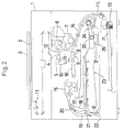
- Figs. 2, 3 show an electrostatic photographic copying machine as one example of an image-forming apparatus according to the present invention.
- reference numeral 1 designates a copying machine body provided with a manuscript-carrying table 2 and a manuscript-weight 3 on an upper surface portion thereof.
- Said copying machine body 1 contains a drum photoreceptor 4 rotating in the direction of an arrow R (in Fig. 2 laid crossways), a charging device 5, developing devices 6, 7, a transfer device 8, a paper-separating device 9, a cleaning device 10 and the like arranged at appointed positions around said photoreceptor 4 in the order described along said rotation direction R and an optical system movement-type exposing device 11 arranged in a space there-above.
- reference numeral 12 designates a deelectrifying device.
- the copying machine body 1 is provided with a supplied paper conveying device 14 for conveying a paper P housed in a cassette 13 adapted to be inserted and extracted from a front side toward said transfer device 8 and a discharge paper-conveying device 16 for conveying said paper P, which has been transferred and separated, toward a fixing device 15.
- a supplied paper conveying device 14 for conveying a paper P housed in a cassette 13 adapted to be inserted and extracted from a front side toward said transfer device 8 and a discharge paper-conveying device 16 for conveying said paper P, which has been transferred and separated, toward a fixing device 15.
- a stocking course 18 for guiding the paper P, which has been fixed, toward a paper-discharging device 17 (its construction will be mentioned later) and a switch-back course 19 for switching back and guiding the paper P toward said paper-discharging device 17 are arranged on the downstream side of said fixing device 15.
- Reference numeral 20 designates a first course-switching over member provided in a branching portion of said both courses 18, 19.
- Reference numerals 21, 22 designate a second course-switching over member and a pair of conveying rollers provided in said switch-back course 19, respectively.
- reference numeral 23 designates a tray (its construction will be mentioned later) provided below said paper-discharging device 17 for receiving the paper P discharged from the paper-discharging device 17 to house it in a certain state.
- Reference numeral 24 designates a paper-resupplying device provided on the downstream side of said tray for jointly supplying the paper P to said supplied paper-conveying device 14 in an appointed timing and reference numeral 25 designates paper-resupplying rollers as paper-resupplying means.
- a complex image is to be formed on said paper P, that is on the one hand manuscript images are to be formed overlappedly on one side or an image is to be formed on both sides on the other hand.
- Reference numeral 26 designates a width-keeping mechanism for keeping the papers P stocked on the tray 23 in uniform width.
- PS designates a paper-stopper.
- the paper-discharging device 17 is provided with three pairs of paper-discharging rollers 27, 28, 29, each comprising an upper roller and a lower roller mounted on a pair of frames (an upper frame and a lower frame) (not shown) at a suitable interval, paper-guiding members 30, 31 arranged between the respective paper-discharging rollers 27, 28, 29, paper-discharging portions 32, 33 arranged immediately downstream of the pair of paper-discharging rollers 27 and the pair of paper-discharging rollers 28, respectively.
- Paper-discharging guides 34, 35 are pivotably mounted immediately downstream of said paper-discharging portions 32, 33, respectively, and a guide member 37 is arranged in a paper-discharging portion 36 composed of the pair of paper-discharging rollers 29 on the downstream side for guiding the paper P downward.
- Said paper-discharging guides 34, 35 can be changed over to a paper-discharging posture for discharging the paper P into the tray 23 crossing a paper-discharging course and a posture for retreating from said paper-discharging course to let the paper P go toward the downstream side.
- a paper P1 of large size having a relatively large length in the conveying direction is guided toward the tray 23 by giving said paper-discharging posture to the paper-discharging guide 34 on the downstream side of the pair of rollers 27, as shown in Fig.
- a paper P2 of middle size is guided toward the tray 23 by giving the paper-discharging posture merely to the paper-discharging guide 35 on the downstream side of the pair of paper-discharging rollers 28 positioned midway, as shown in Fig. 5.
- a paper P3 of small size is guided toward the tray 23 from said paper-discharging portion 31 composed of said pair of paper-discharging rollers 29 on the downstream side by changing-over the two paper-discharging guides 34, 35 to said posture for letting the paper go toward the downstream side, as shown in Fig. 6.
- the papers P1, P2, P3 guided onto the tray 23 through the paper-discharging portions 32, 33, 36, respectively, are uniformly kept in width by means of said width-keeping mechanism 26 regardless of the widths thereof and housed such that the front ends thereof abut against said paper-stopper PS.
- a branching guide 38 is provided on the upstream side of the paper-discharging portion 32 for branching the paper P1 of large size in the direction toward the tray 23. Said branching guide 38, as becomes obvious from the later description, is used for changing-over to a temporary stocking of the paper P within the tray 23 midway between the copying operations and a stocking of the paper P subjected to a final copying step when the paper is copied a plurality of times.
- a pair of paper-discharging rollers 39 composed of an upper paper-discharging roller and a lower paper-discharging roller are mounted on said pair of frames (said upper frame and said lower frame) in the vicinity of a confluence of the stocking course 18 and the switch-back course 19 on the downstream side of said confluence.
- Paper-guiding members 40, 41 are arranged between said pair of paper-discharging rollers 39 and the pair of paper-discharging rollers 27.
- a paper-discharging portion 42 is provided at the immediate downstream side of said pair of paper-discharging rollers 39, and the branching guide 38 is arranged at the downstream portion of said paper-discharging portion 42.
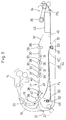
- the position of the branching guide 38 is set so that a front end of the paper P1 does not arrive at the paper-resupplying roller 25, preferably said front end of the paper P1 should not reach to the end portion on the downstream side of a paper-keeping side plate 43 of the width-keeping mechanism 26, when the paper of maximum size (for example the paper P1), on which an image is to be formed by the electrostatic photographic copying machine, is guided toward the tray 23 and deposited there, as shown in Fig. 7.
- the papers P2, P3 shorter than the paper P1 are guided to the branching guide 38 and then housed on the tray 23, as shown in Fig. 8 and Fig. 9, respectively.
- the tray 23 is divided into a first paper-stocking portion 44 for housing all of the papers P subjected to the final copying step or a major part thereof including their rear end, and a second paper-stocking portion 45 for housing a front end part of the paper P to be resupplied.
- Said first paper-stocking portion 44 comprises a first inclined tray portion 46 inclined so as to be slightly lower than the upstream side (the left side in Fig. 1), and having a longer extensional area and a second inclined tray portion 47 inclined so as to be lower than on the downstream side, being shorter and having a smaller area connected with said first inclined tray portion 46.
- Said paper-stocking portion 45 is separated from said second inclined tray portion 47 on the downstream side of the second inclined tray portion 47 and is positioned below the paper-keeping side plate 43 of the width-keeping mechanism 26.
- Tray guide members 48, 49 are arranged crossways in the direction vertical to the paper surface within the image-forming apparatus body 1 while the members 52, 53 to be guided and engaged with said tray guide members 48, 49 are provided on the outer side of a side plate 50 on the upstream side of the first inclined tray portion 46 of the first paper-stocking portion 44 and on the back side of a downwardly bent portion 51 of the second inclined tray portion 47, respectively, so that the first paper-stocking portion 44 can be separately moved from the second paper-stocking portion 45 and can be inserted and extracted from the front side of the image-forming apparatus body 1 (see Fig. 3).
- the paper P to be resupplied or the paper P subjected to the final copying step is housed on the tray 23 having the above-described construction in the following manner.
- the paper P to be resupplied is housed so as to extend over the first paper-stocking portion 44 and the second paper-stocking portion 45 except for paper of remarkably small size. That is to say, the paper P1 of large size is housed on the tray 23 so as to be engaged by the paper-stopper PS at the front end portion thereof and supported by the second paper-stocking portion 45 at a rear end portion thereof, as shown in Fig. 4.
- Paper P2 of middle size and paper P3 of small size are housed on the tray 23 as shown in Fig. 5 and Fig. 6, respectively.
- a paper P subjected to a final copying step is housed merely on the first paper-stocking portion 44 excluding one of relatively large size (for example the paper P1). That is to say, the paper P1 of large size is deposited on the tray 23 so as to be engaged by said side plate 50 on the upstream side of the first inclined tray portion 46 at a rear end B thereof and held by the second paper-stocking portion 45 at said front end portion thereof. And, the paper P2 of middle size and the paper P3 of small size are housed on the tray 23 so as to be held by the first paper-stocking portion 44 as shown in Fig. 8 and Fig. 9, respectively.
- the branching guide 38 Since a manuscript image is usually formed on one side of a paper P merely one time in most cases, the branching guide 38 is held under the condition shown by full line in Fig. 1. Further, it is assumed that the first course-changing over member 20 and the branching guide 38 are changed-over to positions shown by full lines in Fig. 1.
- the manuscript is placed on said manuscript-carrying table 2 and covered with said manuscript weight 3 and then upon pushing down a copy key in an operation display portion 54 (refer to Fig. 3) provided on an upper surface of the image-forming apparatus body 1, said exposing device 11 exposes and scans the manuscript and at the same time the papers P are sent out toward said transfer device 8 from said paper supplying cassette 13 in an appointed timing.
- An electrostatic latent image is formed on the photoreceptor 4 on the basis of said exposure scanning and the formed electrostatic latent image is turned into a toner image by said developing device 6. Said toner image is transferred onto the paper P in the transfer device 8.
- the paper P then passes the fixing device 15 by action of said discharged paper-conveying device 16 to achieve a fixing of the toner image within a predetermined timing.
- the paper P which has been fixed is guided to the stocking course 18 by the first course-changing over member 20 to arrive at the paper-discharging device 17, where it is introduced into the tray 23 through the paper-discharging portion 42 by means of the branching guide 38.
- the paper is housed on the main tray portion 46 on the upstream side of the main tray 23 under the condition that the image-forming surface is faced down.
- the branching guide 38 is arranged on the upstream side of the paper-discharging portion 32 for branching the paper of maximum size, on which an image is to be formed, toward the tray 23 and positioned so that its front end may not arrive at the paper-resupplying rollers 25, so that the front end of the paper P does not arrive at the paper-resupplying rollers 25 even though the paper P arriving at the tray 23 through the paper-discharging portion 42 may not only be small-sized but also large-sized (refer to Figs. 7 to 9).
- the paper P which has been copied and fixed, is stocked on the tray 23, and a copy can be taken out by extracting the main tray portion 47 of the tray 23 to the front side of the image-forming apparatus body 1, as shown in Fig. 3.
- the taking out of paper which has been copied with facing down or up image may be selected by operating the selection key in said operation display portion 54.
- the paper P which has been subjected to the appointed fixing treatment in the first image formation is housed on the tray 23 under the condition that its image faces down, so that the first course-changing over member 20 is held under the state shown by a full line in Fig. 1 and the branching guide 38 is held under the state shown by an imaginary line in Fig. 1.
- the paper-discharging guides 34, 35 are suitably changed over depending upon the size (large, middle, small) of the paper P but now, provided that the manuscript image is overlappedly formed on one side of the paper P of large size, the paper-discharging guide 34 is held under the state shown by said full line in Fig. 1.
- the manuscript Upon operating said copy key under this state, the manuscript is exposed to form an electrostatic latent image on the photoreceptor 4 in the same manner as above described but this electrostatic latent image is first developed by the developing device 6. Then, the paper P1 which has been subjected to the appointed transfer and fixing treatments, is guided to the stocking course 18 by means of the first course-changing over member 20 to arrive at the paper-discharging device 17, where it passes through the branching guide 38 to be introduced into the tray 23 through the paper-discharging portion 32 by means of the paper-discharging guide 34.
- the first course-changing over member 20 and the branching guide 38 are changed over to a position shown by full line in Fig. 1 and an electrostatic latent image is formed on the photoreceptor 4 in the same manner as above described but this time the electrostatic latent image is developed by the other developing device 7.
- the paper P1 which has been subjected to said transfer and fixing treatments, is guided to the stocking course 18 by means of the first course-changing over member 20 to arrive at the paper-discharging device 17 where it is introduced into the tray 23 through the paper-discharging portion 42 by means of the branching guide 38. In this case, it is housed on the tray 23 so as to extend over the first paper-stocking portion 44 and the second paper-stocking portion 45 of the tray 23 with its image facing down, as shown in Fig. 7.
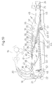
- a fixed guide 55 may be provided above the first inclined tray portion 46.
- a paper P' which has been subjected to the final copying step can be separately housed so as to go under a paper P'' to be resupplied, as shown in Fig. 10.
- first paper-stocking portion 44 can be inserted and extracted from the front side of the image-forming apparatus body 1
- second paper-stocking portion 45 may be adapted to be inserted and extracted from the front side of the image-forming apparatus body 1 in a similar manner.
- the present invention it is sufficient that merely one tray serves not only as the intermediate tray for temporary deposition of the paper but also as the paper-discharging tray for housing the paper on which an appointed image has been formed.
- the conventional intermediate tray is used also as the paper-discharging tray, so that the installing structure of the tray becomes more simple and the required space in height direction for an extra tray becomes unnecessary with the result that an image-forming apparatus according to the invention has a remarkably smaller and compact size.
- the tray housed in the image-forming apparatus body is divided into the first paper-stocking portion for stocking the paper, which has been subjected to the final copying step, and the second paper-stocking portion for stocking the paper to be resupplied, so that the first paper-stocking portion can be simply extracted from for example the front side of the image-forming apparatus body without any hindrance to other members, for example the paper-resupplying rollers.
- the paper which has been subjected to the final copying can be simply taken out by means of a handy tray which can be used very easily.
Abstract
Description
- The present invention relates to an image-forming apparatus for achieving complex image structures such as an overlapped formation of manuscript images on one side of a paper and a formation of an image on both sides of said paper.
- A conventional example of the above-described image-forming apparatus is disclosed in for example Japanese Patent Application Laid-Open No. Hei 1-236 155. This image-forming apparatus comprises an image-forming apparatus body provided with an intermediate tray, a paper-discharging device provided with a plurality of paper-discharging portions and paper-discharging guides that can be switched over to a posture allowing the paper to go toward the downstream side in the respective paper-discharging portions other than a paper-discharging portion on the final end of a paper-discharging course. This known apparatus is further equipped with a paper-resupplying device arranged on the downstream side of said paper-supplying cassette, which is inserted and can be extracted from the front side of said body, and a paper-discharging tray for discharging the paper, on which an image has been formed, housed in the image-forming apparatus body.
- With this known image-forming apparatus the said overlapped formation of manuscript images on one side of the paper and of an image on both sides of the paper can be achieved. The paper-supplying cassette for supplying the paper, on which an image is to be formed, and said paper-discharging tray for discharging the paper, on which said image has been formed, are arranged within said apparatus with the advantage that the body has no projection and thus smaller overall circumference dimensions, with the result that a reduced space is required for installing.
- However, in the above-described conventional image-forming apparatus, said intermediate tray and the paper-discharging tray are separately arranged one above the other and the installing construction becomes complicated and the required vertical space within the image-forming apparatus body increases its height.
- It is an object of the present invention to provide an image-forming section with a simplified construction within the body of an image-forming apparatus, with a reduced height and a compact overall size.
- In order to achieve the above-described object, according to the present invention, in an image-forming apparatus comprising an image-forming apparatus body and a paper-housing device, which can be inserted into and extracted from said image-forming apparatus body, a tray for stocking paper on which an image has been formed, a paper-discharging device provided with a plurality of paper-discharging portions for discharging said paper to said tray and a paper-resupplying device arranged on the downstream side of said paper-discharging device for resupplying the paper stocked in the tray housed in said image-forming apparatus body is characterized in that the tray serving for both, i.e. as an intermediate tray for temporarily stocking the paper midway between copying operations when the paper is copied a plurality of times and as a paper-discharging tray for stocking the paper subject to a final copying process is arranged on the upstream side of said paper-resupplying device, said tray being composed of a first paper-stocking portion and a second paper-stocking portion separated from each other, such that at least a trailing end portion of the paper, which has been subjected to a final copying process is housed on said first paper-stocking portion, whereas a front end side portion of the paper to be resupplied being deposited on said second paper-stocking portion.
- According to the above-described construction, in the case where a complex image is to be formed, that is when the manuscript images should be overlappedly formed on one side of the paper or the image should be formed on both sides of the paper, the paper to be resupplied is housed in the tray under the condition that it arrives at the paper-resupplying means in the paper-resupplying device in the same manner as in a conventional image-forming apparatus of this kind. In this case, the tray serves at the intermediate tray according to the prior art.
- The paper on which the complex image has been formed, and the paper for use in the usual image formation are discharged on the tray through said branching guide but the paper, on which a specific image has been formed, is positioned within the tray under the condition that it does not arrive at the paper-resupplying means even though the paper, on which an image is to be formed, has a maximum size. In this case, the tray serves as the paper-discharging tray according to the prior art.
- The invention and advantageous details thereof will be further explained with reference to the accompanying drawings, in which
- Fig. 1
- is a side view showing a construction of principle parts of an image-forming apparatus according to the present invention;
- Fig. 2
- is a rough longitudinally sectioned side view showing an electrostatic photographic copying machine as one example of said image-forming apparatus;
- Fig. 3
- is a perspective view showing said electrostatic photographic copying machine;
- Figs. 4 to 6
- are side views corresponding to Fig. 1 depicting different operational states of the apparatus housing during paper transportation and paper supply;
- Figs. 7 to 9
- are again side views corresponding to Fig. 1 for showing different operational states of a paper subjected to the final copying; and
- Fig. 10
- is a further side view corresponding to Fig. 1 for showing an operation state of said paper to be resupplied and subjected to a final copying process.
- Figs. 2, 3 show an electrostatic photographic copying machine as one example of an image-forming apparatus according to the present invention. Referring to Figs. 2, 3, reference numeral 1 designates a copying machine body provided with a manuscript-carrying table 2 and a manuscript-
weight 3 on an upper surface portion thereof. Said copying machine body 1 contains adrum photoreceptor 4 rotating in the direction of an arrow R (in Fig. 2 laid crossways), acharging device 5, developingdevices transfer device 8, a paper-separatingdevice 9, acleaning device 10 and the like arranged at appointed positions around saidphotoreceptor 4 in the order described along said rotation direction R and an optical system movement-type exposing device 11 arranged in a space there-above. In addition,reference numeral 12 designates a deelectrifying device. - In addition, the copying machine body 1 is provided with a supplied
paper conveying device 14 for conveying a paper P housed in acassette 13 adapted to be inserted and extracted from a front side toward saidtransfer device 8 and a discharge paper-conveying device 16 for conveying said paper P, which has been transferred and separated, toward afixing device 15. - A
stocking course 18 for guiding the paper P, which has been fixed, toward a paper-discharging device 17 (its construction will be mentioned later) and a switch-back course 19 for switching back and guiding the paper P toward said paper-discharging device 17 are arranged on the downstream side of saidfixing device 15.Reference numeral 20 designates a first course-switching over member provided in a branching portion of said bothcourses Reference numerals back course 19, respectively. - In addition,
reference numeral 23 designates a tray (its construction will be mentioned later) provided below said paper-discharging device 17 for receiving the paper P discharged from the paper-discharging device 17 to house it in a certain state.Reference numeral 24 designates a paper-resupplying device provided on the downstream side of said tray for jointly supplying the paper P to said supplied paper-conveying device 14 in an appointed timing andreference numeral 25 designates paper-resupplying rollers as paper-resupplying means. A complex image is to be formed on said paper P, that is on the one hand manuscript images are to be formed overlappedly on one side or an image is to be formed on both sides on the other hand.Reference numeral 26 designates a width-keeping mechanism for keeping the papers P stocked on thetray 23 in uniform width. PS designates a paper-stopper. - Said constructions of the paper-
discharging device 17 and thetray 23 will be described below with reference to Fig. 1 and Figs. 4 to 9. At first, the paper-discharging device 17 is provided with three pairs of paper-discharging rollers members discharging rollers portions discharging rollers 27 and the pair of paper-discharging rollers 28, respectively. Paper-discharging guides portions guide member 37 is arranged in a paper-dischargingportion 36 composed of the pair of paper-discharging rollers 29 on the downstream side for guiding the paper P downward. - Said paper-
discharging guides tray 23 crossing a paper-discharging course and a posture for retreating from said paper-discharging course to let the paper P go toward the downstream side. For example, a paper P₁ of large size having a relatively large length in the conveying direction is guided toward thetray 23 by giving said paper-discharging posture to the paper-dischargingguide 34 on the downstream side of the pair ofrollers 27, as shown in Fig. 4, while a paper P₂ of middle size is guided toward thetray 23 by giving the paper-discharging posture merely to the paper-dischargingguide 35 on the downstream side of the pair of paper-dischargingrollers 28 positioned midway, as shown in Fig. 5. In addition, a paper P₃ of small size is guided toward thetray 23 from said paper-dischargingportion 31 composed of said pair of paper-discharging rollers 29 on the downstream side by changing-over the two paper-discharging guides tray 23 through the paper-dischargingportions keeping mechanism 26 regardless of the widths thereof and housed such that the front ends thereof abut against said paper-stopper PS. - A branching
guide 38 is provided on the upstream side of the paper-dischargingportion 32 for branching the paper P₁ of large size in the direction toward thetray 23. Said branchingguide 38, as becomes obvious from the later description, is used for changing-over to a temporary stocking of the paper P within thetray 23 midway between the copying operations and a stocking of the paper P subjected to a final copying step when the paper is copied a plurality of times. A pair of paper-discharging rollers 39 composed of an upper paper-discharging roller and a lower paper-discharging roller are mounted on said pair of frames (said upper frame and said lower frame) in the vicinity of a confluence of thestocking course 18 and the switch-back course 19 on the downstream side of said confluence. Paper-guidingmembers discharging rollers 39 and the pair of paper-discharging rollers 27. A paper-dischargingportion 42 is provided at the immediate downstream side of said pair of paper-discharging rollers 39, and the branchingguide 38 is arranged at the downstream portion of said paper-discharging portion 42. The position of the branchingguide 38 is set so that a front end of the paper P₁ does not arrive at the paper-resupplyingroller 25, preferably said front end of the paper P₁ should not reach to the end portion on the downstream side of a paper-keeping side plate 43 of the width-keeping mechanism 26, when the paper of maximum size (for example the paper P₁), on which an image is to be formed by the electrostatic photographic copying machine, is guided toward thetray 23 and deposited there, as shown in Fig. 7. In addition, the papers P₂, P₃ shorter than the paper P₁ are guided to the branchingguide 38 and then housed on thetray 23, as shown in Fig. 8 and Fig. 9, respectively. - The
tray 23 is divided into a first paper-stocking portion 44 for housing all of the papers P subjected to the final copying step or a major part thereof including their rear end, and a second paper-stocking portion 45 for housing a front end part of the paper P to be resupplied. Said first paper-stocking portion 44 comprises a firstinclined tray portion 46 inclined so as to be slightly lower than the upstream side (the left side in Fig. 1), and having a longer extensional area and a secondinclined tray portion 47 inclined so as to be lower than on the downstream side, being shorter and having a smaller area connected with said firstinclined tray portion 46. Said paper-stocking portion 45 is separated from said secondinclined tray portion 47 on the downstream side of the secondinclined tray portion 47 and is positioned below the paper-keepingside plate 43 of the width-keeping mechanism 26. -
Tray guide members members tray guide members side plate 50 on the upstream side of the firstinclined tray portion 46 of the first paper-stocking portion 44 and on the back side of a downwardlybent portion 51 of the secondinclined tray portion 47, respectively, so that the first paper-stocking portion 44 can be separately moved from the second paper-stocking portion 45 and can be inserted and extracted from the front side of the image-forming apparatus body 1 (see Fig. 3). - The paper P to be resupplied or the paper P subjected to the final copying step is housed on the
tray 23 having the above-described construction in the following manner. At first, the paper P to be resupplied is housed so as to extend over the first paper-stocking portion 44 and the second paper-stocking portion 45 except for paper of remarkably small size. That is to say, the paper P₁ of large size is housed on thetray 23 so as to be engaged by the paper-stopper PS at the front end portion thereof and supported by the second paper-stocking portion 45 at a rear end portion thereof, as shown in Fig. 4. Paper P₂ of middle size and paper P₃ of small size are housed on thetray 23 as shown in Fig. 5 and Fig. 6, respectively. - In addition, a paper P subjected to a final copying step is housed merely on the first paper-
stocking portion 44 excluding one of relatively large size (for example the paper P₁). That is to say, the paper P₁ of large size is deposited on thetray 23 so as to be engaged by saidside plate 50 on the upstream side of the firstinclined tray portion 46 at a rear end B thereof and held by the second paper-stocking portion 45 at said front end portion thereof. And, the paper P₂ of middle size and the paper P₃ of small size are housed on thetray 23 so as to be held by the first paper-stocking portion 44 as shown in Fig. 8 and Fig. 9, respectively. - The operation of the image-forming apparatus having the above-described construction will be described in the following.
- Since a manuscript image is usually formed on one side of a paper P merely one time in most cases, the branching
guide 38 is held under the condition shown by full line in Fig. 1. Further, it is assumed that the first course-changing overmember 20 and the branchingguide 38 are changed-over to positions shown by full lines in Fig. 1. - At first, the manuscript is placed on said manuscript-carrying table 2 and covered with said
manuscript weight 3 and then upon pushing down a copy key in an operation display portion 54 (refer to Fig. 3) provided on an upper surface of the image-forming apparatus body 1, said exposingdevice 11 exposes and scans the manuscript and at the same time the papers P are sent out toward saidtransfer device 8 from saidpaper supplying cassette 13 in an appointed timing. An electrostatic latent image is formed on thephotoreceptor 4 on the basis of said exposure scanning and the formed electrostatic latent image is turned into a toner image by said developingdevice 6. Said toner image is transferred onto the paper P in thetransfer device 8. The paper P then passes the fixingdevice 15 by action of said discharged paper-conveyingdevice 16 to achieve a fixing of the toner image within a predetermined timing. - The paper P which has been fixed is guided to the
stocking course 18 by the first course-changing overmember 20 to arrive at the paper-dischargingdevice 17, where it is introduced into thetray 23 through the paper-dischargingportion 42 by means of the branchingguide 38. In this case, the paper is housed on themain tray portion 46 on the upstream side of themain tray 23 under the condition that the image-forming surface is faced down. In this case, the branchingguide 38 is arranged on the upstream side of the paper-dischargingportion 32 for branching the paper of maximum size, on which an image is to be formed, toward thetray 23 and positioned so that its front end may not arrive at the paper-resupplyingrollers 25, so that the front end of the paper P does not arrive at the paper-resupplyingrollers 25 even though the paper P arriving at thetray 23 through the paper-dischargingportion 42 may not only be small-sized but also large-sized (refer to Figs. 7 to 9). - After a copying cycle, the paper P, which has been copied and fixed, is stocked on the
tray 23, and a copy can be taken out by extracting themain tray portion 47 of thetray 23 to the front side of the image-forming apparatus body 1, as shown in Fig. 3. - On the other hand, in the case where the first course-changing over
member 20 and the second course-changing overmember 21 are switched to the state shown by an imaginary line in Fig. 1, the paper P which has been fixed, arrives at the paper-dischargingdevice 17 through the switch-back course 19 and is housed with the image-forming surface facing up. - In addition, the taking out of paper which has been copied with facing down or up image may be selected by operating the selection key in said
operation display portion 54. - Subsequently, in the case where a manuscript image is to be overlappedly formed on one side of the paper to obtain for example a bi-colored copy, a selection key for setting such the copying mode in the
operation display portion 54 is operated. - In this copying mode, it is required that the paper P which has been subjected to the appointed fixing treatment in the first image formation, is housed on the
tray 23 under the condition that its image faces down, so that the first course-changing overmember 20 is held under the state shown by a full line in Fig. 1 and the branchingguide 38 is held under the state shown by an imaginary line in Fig. 1. The paper-dischargingguides guide 34 is held under the state shown by said full line in Fig. 1. - Upon operating said copy key under this state, the manuscript is exposed to form an electrostatic latent image on the
photoreceptor 4 in the same manner as above described but this electrostatic latent image is first developed by the developingdevice 6. Then, the paper P₁ which has been subjected to the appointed transfer and fixing treatments, is guided to thestocking course 18 by means of the first course-changing overmember 20 to arrive at the paper-dischargingdevice 17, where it passes through the branchingguide 38 to be introduced into thetray 23 through the paper-dischargingportion 32 by means of the paper-dischargingguide 34. In this case, however, it is housed on thetray 23 under the condition that it extends over the second paper-stockingportion 45 of thetray 23 and the downstream side portion of the first paper-stockingportion 44 and with facing down image. The papers P₁ stocked on thetray 23 are kept in width by means of the width-keepingmechanism 26, as shown in Fig. 4. - After the completion of the first copying cycle, upon operating a paper-resupplying key in the
operation display portion 54, the first course-changing overmember 20 and the branchingguide 38 are changed over to a position shown by full line in Fig. 1 and an electrostatic latent image is formed on thephotoreceptor 4 in the same manner as above described but this time the electrostatic latent image is developed by the other developingdevice 7. The paper P₁ which has been subjected to said transfer and fixing treatments, is guided to thestocking course 18 by means of the first course-changing overmember 20 to arrive at the paper-dischargingdevice 17 where it is introduced into thetray 23 through the paper-dischargingportion 42 by means of the branchingguide 38. In this case, it is housed on thetray 23 so as to extend over the first paper-stockingportion 44 and the second paper-stockingportion 45 of thetray 23 with its image facing down, as shown in Fig. 7. - In the case where an image is to be formed on both sides of the paper, the operation is same as that in the case where the image is overlappedly formed on one side of the paper except that the paper P which has been subjected to the transfer and fixing treatments on one side thereof, is housed on the
tray 23 with facing up image, so that its detailed description is omitted. - Furthermore, a fixed
guide 55 may be provided above the firstinclined tray portion 46. In this case, a paper P' which has been subjected to the final copying step, can be separately housed so as to go under a paper P'' to be resupplied, as shown in Fig. 10. - In the image-forming apparatus having the above described construction, other copying modes than those described above are possible but the description is omitted here.
- Although in the above described preferred embodiment the first paper-stocking
portion 44 can be inserted and extracted from the front side of the image-forming apparatus body 1, according to a further modification, also the second paper-stockingportion 45 may be adapted to be inserted and extracted from the front side of the image-forming apparatus body 1 in a similar manner. - As above described, according to the present invention, it is sufficient that merely one tray serves not only as the intermediate tray for temporary deposition of the paper but also as the paper-discharging tray for housing the paper on which an appointed image has been formed. In other words, according to the invention, the conventional intermediate tray is used also as the paper-discharging tray, so that the installing structure of the tray becomes more simple and the required space in height direction for an extra tray becomes unnecessary with the result that an image-forming apparatus according to the invention has a remarkably smaller and compact size.
- According to the present invention, the tray housed in the image-forming apparatus body is divided into the first paper-stocking portion for stocking the paper, which has been subjected to the final copying step, and the second paper-stocking portion for stocking the paper to be resupplied, so that the first paper-stocking portion can be simply extracted from for example the front side of the image-forming apparatus body without any hindrance to other members, for example the paper-resupplying rollers. Thus, the paper which has been subjected to the final copying, can be simply taken out by means of a handy tray which can be used very easily.
- As a specific advantage of the present invention, it is not required to dislocate and specially control the part of the machine having many movable portions, such as the paper-resupplying means. This means that the construction becomes more simple and the reliability is improved at reduced cost.
Claims (16)
- An image-forming apparatus comprising an image-forming apparatus body (1), a paper-housing device (13) which can be inserted into and extracted from said image-forming apparatus body, a tray (23) for stocking paper on which an image has been formed, a paper-discharging device (17) provided with a plurality of paper-discharging portions (32, 33, 36) for discharging said paper to said tray and a paper-resupplying device (24) arranged on the downstream side of said paper-discharging device for resupplying the paper stocked in the tray housed in said image-forming apparatus body, characterized in that the tray (23) serving for both, i.e. as an intermediate tray for temporarily stocking the paper (P) midway between copying operations when the paper is copied a plurality of times and as a paper-discharging tray for stocking the paper subjected to a final copying process is arranged on the upstream side of said paper-resupplying device (24), said tray (23) being composed of a first paper-stocking portion (44) and a second paper-stocking portion (45) separated from each other, such that at least a trailing end portion of the paper (P), which has been subjected to a final copying process, is housed on said first paper-stocking portion (44), whereas a front end side portion of the paper to be resupplied being deposited on said second paper-stocking portion (45).
- The image-forming apparatus as set forth in claim 1, wherein the first paper-stocking portion (44) comprises a long inclined tray portion (44) inclined so as to be lower on the upstream side thereof for supporting a major large area of said copied paper.
- The image-forming apparatus as set forth in claim 1, wherein the first paper-stocking portion (44) comprises a first long inclined tray portion (46) inclined so as to be lower on the upstream side thereof and a second short inclined tray portion (47) having a smaller area than said first inclined tray portion and being inclined so as to be lower on the downstream side thereof and connected with said first inclined tray portion, and wherein said second paper-stocking portion (45) is arranged on the downstream side of and separated from said second inclined tray portion (47).
- The image-forming apparatus as set forth in claim 3, wherein tray guide members (48, 49) are arranged crossways within said image-forming apparatus body (1) while members (52, 53) to be guided and engaging with said tray guide members are provided on both sides of the first paper-stocking portion (44) such that the first paper-stocking portion (44) can be separated from the second paper-stocking portion (45) to be inserted and extracted from the front side of the image-forming apparatus body (1).
- The image-forming apparatus as set forth in claim 1, wherein the paper-discharging device (17) is provided with a branching guide (38) arranged on the upstream side of said paper-discharging portion for branching off the paper (P₁) of maximum size bearing a copied image toward the tray (23) and to position said paper (P₁) so that a front end thereof housed on the tray does not reach to the paper-resupplying means (25) in said paper-resupplying device (24).
- The image-forming apparatus as set forth in claim 5, wherein the paper-discharging device (17) is provided with a pair of paper-discharging rollers (39) on the upstream side of said branching guide (38) and said plurality of paper-discharging portions comprising associated pairs of paper-discharging rollers (27, 28, 29) and a paper-discharging guide positioned on the downstream side of each pair of paper-discharging rollers for guiding the paper moving through a conveying course arranged at suitable intervals on the downstream side of the branching guide (38).
- The image-forming apparatus as set forth in claim 1, wherein a fixed guide (55) is provided above a first inclined tray portion of the first paper-stocking portion for guiding the paper discharged from the paper-discharging portion when paper (P₁) of maximum size is sent to the paper-supplying means and for supporting a rear end portion of the paper when it is stocked.
- An image-forming apparatus comprising an image-forming apparatus body (1), and a paper-housing device (13), which can be inserted into and extracted from said image-forming body, a tray (23) for stocking paper, on which an image has been formed, a paper-discharging device (17) provided with a plurality of paper-discharging portions (32, 33, 36) for discharging said paper to said tray and a paper-resupplying device (24) arranged on the downstream side of said paper-discharging device for resupplying the paper stocked in the tray housed in said image-forming apparatus body, characterized in that the tray serving for both, i.e. as an intermediate tray for temporarily stocking the paper (P) midway between copying operations when the paper is copied a plurality of times and as a paper-discharging tray for stocking the paper subjected to a final copying process, is arranged on the upstream side of said paper-resupplying device (24), said tray (23) being composed of a first paper-stocking portion (44) and a second paper-stocking portion (45), and a branching guide (38) for branching the paper (P₁) of maximum size, on which an image has been formed, to the tray (23) in the paper-discharging device is arranged at a position where the paper (P₁) of maximum size guided toward the tray and housed within the tray does not reach to the paper-resupplying means (25) in said paper-resupplying device (24) and at a front end of the upstream side of the paper-discharging portion.
- The image-forming apparatus as set forth in claim 8, wherein the dimensions of said first paper-stocking portion and said second paper-stocking portion are such that the paper (P₁) of maximum size housed on the tray extends over both portions.
- The image-forming apparatus as set forth in claim 9, wherein a portion of the rear end side of the paper, which has been subjected to the final copying process, is housed on the first paper-stocking portion while a front end side of the paper to be resupplied is housed in the second paper-stocking portion.
- The image-forming apparatus as set forth in claim 10, wherein the first paper-stocking portion (46) comprises a long inclined tray portion inclined so as to be lower on the upstream side thereof and having a larger area than said second paper-stocking portion (47).
- The image-forming apparatus as set forth in claim 10, wherein said first paper-stocking portion (46) comprises a first long inclined tray portion inclined so as to be lower on the upstream side thereof and having a large area than said second paper-stocking portion which is shorter and inclined so as to be lower on the downstream side thereof, both tray portions being connected, and wherein the second paper-stocking portion (45) is arranged on the downstream side of said second inclined tray portion (47) but separated from the second inclined tray portion.
- The image-forming apparatus as set forth in claim 12, wherein tray guide members (48, 49) are arranged crossways within said image-forming apparatus body (1) while members (52, 53) to be guided and engaging with said tray guide members are provided on both sides of the first paper-stocking portion (44) such that the first paper-stocking portion (44) can be separated from the second paper-stocking portion (45) to be inserted and extracted from the front side of the image-forming apparatus body (1).
- The image-forming apparatus as set forth in claim 12, wherein the first paper-stocking portion (44) and the second paper-stocking portion (45) are separated from each other.
- The image-forming apparatus as set forth in claim 10, wherein the paper-discharging device (17) is provided with a pair of paper-discharging rollers (39) on the upstream side of said branching guide (38) and said plurality of paper-discharging portions comprising associated pairs of paper-discharging rollers (27, 28, 29) and a paper-discharging guide positioned on the downstream side of each pair of paper-discharging rollers for guiding the paper moving through a conveying course arranged at suitable intervals on the downstream side of the branching guide (38).
- The image-forming apparatus as set forth in claim 10, wherein a fixed guide (55) is provided above a first inclined tray portion of the first paper-stocking portion for guiding the paper discharged from the paper-discharging portion when paper (P₁) of maximum size is sent to paper-supplying means and for supporting a rear end portion of the paper when it is stocked.
Applications Claiming Priority (2)
| Application Number | Priority Date | Filing Date | Title |
|---|---|---|---|
| JP2312186A JPH0818765B2 (en) | 1990-11-17 | 1990-11-17 | Image forming device |
| JP312186/90 | 1990-11-17 |
Publications (3)
| Publication Number | Publication Date |
|---|---|
| EP0486972A2 true EP0486972A2 (en) | 1992-05-27 |
| EP0486972A3 EP0486972A3 (en) | 1992-11-19 |
| EP0486972B1 EP0486972B1 (en) | 1995-05-10 |
Family
ID=18026256
Family Applications (1)
| Application Number | Title | Priority Date | Filing Date |
|---|---|---|---|
| EP19910119558 Expired - Lifetime EP0486972B1 (en) | 1990-11-17 | 1991-11-15 | Image-forming apparatus |
Country Status (3)
| Country | Link |
|---|---|
| EP (1) | EP0486972B1 (en) |
| JP (1) | JPH0818765B2 (en) |
| DE (1) | DE69109628T2 (en) |
Families Citing this family (1)
| Publication number | Priority date | Publication date | Assignee | Title |
|---|---|---|---|---|
| JP4586347B2 (en) * | 2003-10-07 | 2010-11-24 | 富士ゼロックス株式会社 | Parallel processing printer |
Citations (3)
| Publication number | Priority date | Publication date | Assignee | Title |
|---|---|---|---|---|
| US3989236A (en) * | 1973-12-13 | 1976-11-02 | Canon Kabushiki Kaisha | Copying machine |
| US4734744A (en) * | 1986-02-20 | 1988-03-29 | Sharp Kabushiki Kaisha | Jam detector for intermediate tray of a copying machine |
| EP0378177A2 (en) * | 1989-01-10 | 1990-07-18 | Canon Kabushiki Kaisha | Image forming apparatus |
-
1990
- 1990-11-17 JP JP2312186A patent/JPH0818765B2/en not_active Expired - Lifetime
-
1991
- 1991-11-15 EP EP19910119558 patent/EP0486972B1/en not_active Expired - Lifetime
- 1991-11-15 DE DE1991609628 patent/DE69109628T2/en not_active Expired - Fee Related
Patent Citations (3)
| Publication number | Priority date | Publication date | Assignee | Title |
|---|---|---|---|---|
| US3989236A (en) * | 1973-12-13 | 1976-11-02 | Canon Kabushiki Kaisha | Copying machine |
| US4734744A (en) * | 1986-02-20 | 1988-03-29 | Sharp Kabushiki Kaisha | Jam detector for intermediate tray of a copying machine |
| EP0378177A2 (en) * | 1989-01-10 | 1990-07-18 | Canon Kabushiki Kaisha | Image forming apparatus |
Also Published As
| Publication number | Publication date |
|---|---|
| JPH0818765B2 (en) | 1996-02-28 |
| DE69109628T2 (en) | 1996-01-18 |
| DE69109628D1 (en) | 1995-06-14 |
| EP0486972B1 (en) | 1995-05-10 |
| JPH04182277A (en) | 1992-06-29 |
| EP0486972A3 (en) | 1992-11-19 |
Similar Documents
| Publication | Publication Date | Title |
|---|---|---|
| US6757516B2 (en) | Carrying apparatus and image forming apparatus | |
| US4050805A (en) | Electrophotographic copying apparatus for two-sided copying | |
| JP2851303B2 (en) | Printer device | |
| JPH0820785B2 (en) | Copier | |
| JPH02305057A (en) | Printer device | |
| US6085063A (en) | Digital image forming apparatus | |
| US5216474A (en) | Imase-forming apparatus with tray | |
| JPH07179250A (en) | Automatic printing device | |
| JPH11157726A (en) | Image forming device | |
| JP2809654B2 (en) | Image forming device | |
| EP0486972B1 (en) | Image-forming apparatus | |
| EP0383983B1 (en) | Image forming apparatus | |
| JPS62151871A (en) | Electrophotographic device | |
| JP2981236B2 (en) | Image forming device | |
| JP3530311B2 (en) | Image forming device | |
| JP3772956B2 (en) | Image forming apparatus and sheet supply unit used therefor | |
| JPS6123075A (en) | Sheet-member processing apparatus | |
| JPH01162657A (en) | Intermediate sheet accommodating device | |
| US5923436A (en) | Facsimile machine | |
| JPH01214568A (en) | Automatic original carriage device for copying machine | |
| JP3881820B2 (en) | Image forming apparatus | |
| JP2893939B2 (en) | Control device of transfer assisting means of image forming apparatus | |
| JP2001222139A (en) | Double-sided device | |
| JPH066369Y2 (en) | Paper feeding device of image forming apparatus | |
| JPH0818766B2 (en) | Image forming device |
Legal Events
| Date | Code | Title | Description |
|---|---|---|---|
| PUAI | Public reference made under article 153(3) epc to a published international application that has entered the european phase |
Free format text: ORIGINAL CODE: 0009012 |
|
| AK | Designated contracting states |
Kind code of ref document: A2 Designated state(s): DE FR GB IT |
|
| PUAL | Search report despatched |
Free format text: ORIGINAL CODE: 0009013 |
|
| AK | Designated contracting states |
Kind code of ref document: A3 Designated state(s): DE FR GB IT |
|
| 17P | Request for examination filed |
Effective date: 19921123 |
|
| 17Q | First examination report despatched |
Effective date: 19940801 |
|
| GRAA | (expected) grant |
Free format text: ORIGINAL CODE: 0009210 |
|
| AK | Designated contracting states |
Kind code of ref document: B1 Designated state(s): DE FR GB IT |
|
| REF | Corresponds to: |
Ref document number: 69109628 Country of ref document: DE Date of ref document: 19950614 |
|
| ITF | It: translation for a ep patent filed |
Owner name: STUDIO TORTA SOCIETA' SEMPLICE |
|
| ET | Fr: translation filed | ||
| PLBE | No opposition filed within time limit |
Free format text: ORIGINAL CODE: 0009261 |
|
| STAA | Information on the status of an ep patent application or granted ep patent |
Free format text: STATUS: NO OPPOSITION FILED WITHIN TIME LIMIT |
|
| 26N | No opposition filed | ||
| PGFP | Annual fee paid to national office [announced via postgrant information from national office to epo] |
Ref country code: GB Payment date: 19961106 Year of fee payment: 6 |
|
| PGFP | Annual fee paid to national office [announced via postgrant information from national office to epo] |
Ref country code: DE Payment date: 19961122 Year of fee payment: 6 |
|
| PG25 | Lapsed in a contracting state [announced via postgrant information from national office to epo] |
Ref country code: GB Free format text: LAPSE BECAUSE OF NON-PAYMENT OF DUE FEES Effective date: 19971115 |
|
| PGFP | Annual fee paid to national office [announced via postgrant information from national office to epo] |
Ref country code: FR Payment date: 19971128 Year of fee payment: 7 |
|
| GBPC | Gb: european patent ceased through non-payment of renewal fee |
Effective date: 19971115 |
|
| PG25 | Lapsed in a contracting state [announced via postgrant information from national office to epo] |
Ref country code: DE Free format text: LAPSE BECAUSE OF NON-PAYMENT OF DUE FEES Effective date: 19980801 |
|
| REG | Reference to a national code |
Ref country code: FR Ref legal event code: ST |
|
| PG25 | Lapsed in a contracting state [announced via postgrant information from national office to epo] |
Ref country code: FR Free format text: THE PATENT HAS BEEN ANNULLED BY A DECISION OF A NATIONAL AUTHORITY Effective date: 19981130 |
|
| PG25 | Lapsed in a contracting state [announced via postgrant information from national office to epo] |
Ref country code: IT Free format text: LAPSE BECAUSE OF NON-PAYMENT OF DUE FEES Effective date: 20051115 |