EP0486314A1 - A dishwasher lid - Google Patents
A dishwasher lid Download PDFInfo
- Publication number
- EP0486314A1 EP0486314A1 EP91310543A EP91310543A EP0486314A1 EP 0486314 A1 EP0486314 A1 EP 0486314A1 EP 91310543 A EP91310543 A EP 91310543A EP 91310543 A EP91310543 A EP 91310543A EP 0486314 A1 EP0486314 A1 EP 0486314A1
- Authority
- EP
- European Patent Office
- Prior art keywords
- lid
- sink
- lid assembly
- hinge
- assembly
- Prior art date
- Legal status (The legal status is an assumption and is not a legal conclusion. Google has not performed a legal analysis and makes no representation as to the accuracy of the status listed.)
- Ceased
Links
- 239000007788 liquid Substances 0.000 claims description 6
- 238000009423 ventilation Methods 0.000 claims description 6
- 239000012530 fluid Substances 0.000 claims description 4
- 238000013022 venting Methods 0.000 claims description 3
- 230000000694 effects Effects 0.000 claims description 2
- XLYOFNOQVPJJNP-UHFFFAOYSA-N water Substances O XLYOFNOQVPJJNP-UHFFFAOYSA-N 0.000 description 5
- 238000005406 washing Methods 0.000 description 4
- 125000006850 spacer group Chemical group 0.000 description 2
- 239000000853 adhesive Substances 0.000 description 1
- 230000001070 adhesive effect Effects 0.000 description 1
- 239000006185 dispersion Substances 0.000 description 1
- 238000012986 modification Methods 0.000 description 1
- 230000004048 modification Effects 0.000 description 1
- 229910001220 stainless steel Inorganic materials 0.000 description 1
- 239000010935 stainless steel Substances 0.000 description 1
Images


Classifications
-
- A—HUMAN NECESSITIES
- A47—FURNITURE; DOMESTIC ARTICLES OR APPLIANCES; COFFEE MILLS; SPICE MILLS; SUCTION CLEANERS IN GENERAL
- A47L—DOMESTIC WASHING OR CLEANING; SUCTION CLEANERS IN GENERAL
- A47L15/00—Washing or rinsing machines for crockery or tableware
- A47L15/0086—In-sink dishwashers
-
- A—HUMAN NECESSITIES
- A47—FURNITURE; DOMESTIC ARTICLES OR APPLIANCES; COFFEE MILLS; SPICE MILLS; SUCTION CLEANERS IN GENERAL
- A47L—DOMESTIC WASHING OR CLEANING; SUCTION CLEANERS IN GENERAL
- A47L15/00—Washing or rinsing machines for crockery or tableware
- A47L15/42—Details
- A47L15/4251—Details of the casing
- A47L15/4257—Details of the loading door
-
- A—HUMAN NECESSITIES
- A47—FURNITURE; DOMESTIC ARTICLES OR APPLIANCES; COFFEE MILLS; SPICE MILLS; SUCTION CLEANERS IN GENERAL
- A47L—DOMESTIC WASHING OR CLEANING; SUCTION CLEANERS IN GENERAL
- A47L15/00—Washing or rinsing machines for crockery or tableware
- A47L15/42—Details
- A47L15/4251—Details of the casing
- A47L15/4257—Details of the loading door
- A47L15/4261—Connections of the door to the casing, e.g. door hinges
-
- A—HUMAN NECESSITIES
- A47—FURNITURE; DOMESTIC ARTICLES OR APPLIANCES; COFFEE MILLS; SPICE MILLS; SUCTION CLEANERS IN GENERAL
- A47L—DOMESTIC WASHING OR CLEANING; SUCTION CLEANERS IN GENERAL
- A47L15/00—Washing or rinsing machines for crockery or tableware
- A47L15/42—Details
- A47L15/48—Drying arrangements
- A47L15/488—Connections of the tub with the ambient air, e.g. air intake or venting arrangements
Definitions
- the present invention relates to a dishwasher lid and more particularly, though not exclusively, to a hinged lid applicable for a sink type dishwasher.
- a lid In known sink type dishwashers which comprise a tub into which dishes and the like are placed through an upper opening thereof for washing, a lid may be provided.
- the present invention provides a lid assembly for a sink type dishwasher or like vessel, the lid assembly comprising a lid adapted to be fixed by a spring loaded hinge means to a periphery of a sink, and ventilation means adapted to allow fluid communication between the interior of said sink and atmosphere, the ventilation means being provided in a region of said spring loaded hinge means and comprising means to prevent splashing liquid from within the sink passing therethrough.
- the fluid communication only permits the venting of vapour to atmosphere.
- said spring loaded hinge means effects a biasing of said lid into an open configuration.
- the lid is provided with a catch which serves to retain said lid in a closed configuration.
- the lid when in an open configuration is adapted to be detached from said region adjacent to said periphery of said sink.
- the air ventilation means is provided in the form of a channel extending below said spring operated hinge means and provides a tortuous path through which said vapour and/or air can pass while splashed liquid may not.
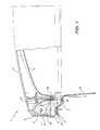
- a lid assembly 1 as seen in Fig. 1, the assembly 1 has a plastic lid outer 2 and a stainless steel lid inner 3 pivotally supported by a hinge shaft 4 above a sink 8.
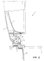
- the hinge shaft 4 (better seen in Figs. 5A and 5B) is surrounded by a hinge spring 5 (Figs. 4A and 4B) which biases the lid 2, 3 towards an open configuration as depicted in Fig. 2.
- the hinge shaft 4 and hinge spring 5 are located within a hinge cover 9.
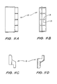
- Located below the hinge cover (Fig.10) is an airvent 6 (Fig. 11) through which vapour and/or airfrom within the sink 8 can escape.
- a resilient seal 14 is attached to lid inner 3 by any suitable means such as an interference fit or by an adhesive.
- the seal 14 is adapted to engage with a lower portion of the hinge cover 9 so as to prevent escape of vapour and/or liquid therepast.
- the assembly 1 is mounted to the sink 8 by way of sink bracket 11, hinge bracket 12 and bracket support 7. These various components parts are best depicted in further detail in Figs. 7, 8 and 9.
- the hinge shaft 4 is insertable through the spring 5 and mounted on the hinge bracket 12 using a hinge spacer 15 (seen in Figs. 6A and 6B) locatable about the shaft 4 behind pin receiving aperture 16.
- the lid assembly 1 When assembled as shown, the lid assembly 1 can be removed from sink 8 by detaching a threaded fastener which penetrates the hinge bracket 12, sink bracket 11, and hinge cover 9.
- a threaded fastener can be omitted in a configuration which allows for the lid assembly 1 to be detached from the sink 8 in an open position as depicted in Fig. 2 allowing the hinge parts to be slid apart.
- the sink 8 In use, articles to be washed such as dishes and cutlery are placed within the sink 8 in a conventional manner.
- the sink 8 is provided with some form of rotary water dispersion device or dishwasher which directs water generally upwardly from a lower region thereof to wash the dishes.
- the lid 2,3 is then closed over the sink 8 and locked down by way of a catch or latch (not shown but known to those in the art).
- a catch or latch not shown but known to those in the art.
- vapour and/or air is allowed to escape from the sink 8 via the vent 6 to atmosphere.
- the vent 6 is provided with various obstacles 13 which form a honeycomb-like configuration and constitute a tortuous path and accordingly splashed water is not allowed to escape to atmosphere therethrough.
- the lid 2,3 can be opened so as to be biased into a generally vertical orientation by way of the spring 5. In this open configuration, the lid 2,3 can be removed by detaching screws (not shown) or by sliding in a direction generally parallel to hinge shaft 4.
- vent passage 6 can be provided through lid 2,3 rather than below hinge cover 9.
Landscapes
- Washing And Drying Of Tableware (AREA)
- Closures For Containers (AREA)
- Detergent Compositions (AREA)
Abstract
A dishwasher lid assembly (1) is disclosed which includes a lid having upper (2) and lower (3) portions. The lid (2,3) is pivotally supported by a hinge shaft (4) above a sink (8). A hinge spring (5) surrounds the shaft (4) and biases the lid (2,3) to an open configuration. A latch can be used to retain the lid (2,3) closed. The shaft (4) and spring (5) are located within a hinge cover (9) below which is an air vent (6) arranged to permit vapour and/or air within the sink (8) to escape, thus preventing a build-up of pressure under the lid (2,3).
Description
- The present invention relates to a dishwasher lid and more particularly, though not exclusively, to a hinged lid applicable for a sink type dishwasher.
- In known sink type dishwashers which comprise a tub into which dishes and the like are placed through an upper opening thereof for washing, a lid may be provided.
- As the water used in such dishwashers is often quite hot, a build up of pressure within the dishwasher results. Such build up of pressure is clearly undesirable in terms of safety and efficiency for example.
- It is an object of the present invention to substantially overcome, orameliorate these problems through provision of a lid for a sink type dishwasher or like vessel with a venting means to vent air and/or vapour therefrom without allowing passage of liquid therethrough.
- In one broad form, the present invention provides a lid assembly for a sink type dishwasher or like vessel, the lid assembly comprising a lid adapted to be fixed by a spring loaded hinge means to a periphery of a sink, and ventilation means adapted to allow fluid communication between the interior of said sink and atmosphere, the ventilation means being provided in a region of said spring loaded hinge means and comprising means to prevent splashing liquid from within the sink passing therethrough.
- Generally, the fluid communication only permits the venting of vapour to atmosphere.
- Advantageously, said spring loaded hinge means effects a biasing of said lid into an open configuration.
- Generally, the lid is provided with a catch which serves to retain said lid in a closed configuration.
- Beneficially, the lid, when in an open configuration is adapted to be detached from said region adjacent to said periphery of said sink.
- Preferably, the air ventilation means is provided in the form of a channel extending below said spring operated hinge means and provides a tortuous path through which said vapour and/or air can pass while splashed liquid may not.
- A preferred embodient of the present invention will now be described by way of example with reference to the accompanying drawings, wherein:
- Fig. 1 is a cross-sectional side elevational view of a lid assembly in a closed configuration;
- Fig. 2 is a view similar to Fig. 1 of the lid assembly in an open configuration;
- Fig. 3 is a elevational view of the lid assembly in Fig. 2.
- Figs. 4A and 4B show plan and end elevational views of the hinge spring of Figs. 1 to 3;
- Figs. 5A and 5B show corresponding view of the hinge shaft;
- Figs. 6A and 6B show end and plan elevation views of the hinge spacer;
- Figs. 7A, 7B and 7C show end, plan and side elevation views of the hinge bracket;
- Figs. 8A, 8B and 8C are corresponding views of the sink bracket;
- Figs. 9A, 9B and 9C are corresponding views of the bracket support;
- Figs. 10A, 10B, 10C and 10D show respectively front, bottom, side and sectional views of the hinge cover; and
- Figs.11A, 11 B, 11 C and 11 D show coresponding views of the air vent.
- In the accompanying drawings there is schematically depicted a lid assembly 1. as seen in Fig. 1, the assembly 1 has a plastic lid outer 2 and a stainless steel lid inner 3 pivotally supported by a
hinge shaft 4 above a sink 8. - The hinge shaft 4 (better seen in Figs. 5A and 5B) is surrounded by a hinge spring 5 (Figs. 4A and 4B) which biases the
lid hinge shaft 4 andhinge spring 5 are located within a hinge cover 9. Located below the hinge cover (Fig.10) is an airvent 6 (Fig. 11) through which vapour and/or airfrom within the sink 8 can escape. - A
resilient seal 14 is attached to lid inner 3 by any suitable means such as an interference fit or by an adhesive. Theseal 14 is adapted to engage with a lower portion of the hinge cover 9 so as to prevent escape of vapour and/or liquid therepast. - The assembly 1 is mounted to the sink 8 by way of
sink bracket 11,hinge bracket 12 andbracket support 7. These various components parts are best depicted in further detail in Figs. 7, 8 and 9. - The
hinge shaft 4 is insertable through thespring 5 and mounted on thehinge bracket 12 using a hinge spacer 15 (seen in Figs. 6A and 6B) locatable about theshaft 4 behindpin receiving aperture 16. - When assembled as shown, the lid assembly 1 can be removed from sink 8 by detaching a threaded fastener which penetrates the
hinge bracket 12,sink bracket 11, and hinge cover 9. Alternatively, such a threaded fastener can be omitted in a configuration which allows for the lid assembly 1 to be detached from the sink 8 in an open position as depicted in Fig. 2 allowing the hinge parts to be slid apart. - In use, articles to be washed such as dishes and cutlery are placed within the sink 8 in a conventional manner. It should be appreciated that the sink 8 is provided with some form of rotary water dispersion device or dishwasher which directs water generally upwardly from a lower region thereof to wash the dishes. The
lid vent 6 to atmosphere. Thevent 6 is provided withvarious obstacles 13 which form a honeycomb-like configuration and constitute a tortuous path and accordingly splashed water is not allowed to escape to atmosphere therethrough. - Upon completion of washing, since no build up of pressure within the sink has been allowed, the
lid spring 5. In this open configuration, thelid shaft 4. - The foregoing describes only one embodiment of the present invention and modifications, obvious to those skilled in the art can be made thereto without departing from the scope of the present invention. For example, the
vent passage 6 can be provided throughlid
Claims (6)
1. A lid assembly for a sink type dishwasher or like vessel, said lid assembly characterised in that there is provided a lid adapted to be fixed by a spring loaded hinge means to a periphery of a sink, and ventilation means adapted to allow fluid communication between the interior of said sink and atmosphere, the ventilation means being provided in a region of said spring loaded hinge means and comprising means to prevent splashing liquid from within the sink passing therethrough.
2. A lid assembly as claimed in claim 1, characterised in that said spring loaded hinge means effects a biasing of said lid into an open configuration.
3. A lid assembly as claimed in claim 1 or 2, characterised in that the lid is provided with a catch which serves to retain said lid in a closed configuration.
4. A lid assembly as claimed in claim 1, 2 or 3, characterised in that the lid, when in an open configuration, is adapted to be detached from said region adjacent to said periphery of said sink.
5. A lid assembly as claimed in any one of claims 1 to 4, characterised in that the air ventilation means is provided in the form of a channel extending below said spring operated hinge means and provides a tortuous path through which said vapour and/or air can pass while splashed liquid may not.
6. A lid assembly as claimed in any one of the preceding claims, characterised in that said fluid communication only involves the venting of vapour from within said sink to atmosphere.
Applications Claiming Priority (2)
| Application Number | Priority Date | Filing Date | Title |
|---|---|---|---|
| AUPK337890 | 1990-11-15 | ||
| AU3378/90 | 1990-11-15 |
Publications (1)
| Publication Number | Publication Date |
|---|---|
| EP0486314A1 true EP0486314A1 (en) | 1992-05-20 |
Family
ID=3775074
Family Applications (1)
| Application Number | Title | Priority Date | Filing Date |
|---|---|---|---|
| EP91310543A Ceased EP0486314A1 (en) | 1990-11-15 | 1991-11-14 | A dishwasher lid |
Country Status (5)
| Country | Link |
|---|---|
| US (1) | US5178172A (en) |
| EP (1) | EP0486314A1 (en) |
| JP (1) | JPH0622893A (en) |
| CA (1) | CA2055559A1 (en) |
| NZ (1) | NZ240553A (en) |
Cited By (3)
| Publication number | Priority date | Publication date | Assignee | Title |
|---|---|---|---|---|
| US6491049B1 (en) * | 1998-09-21 | 2002-12-10 | Maytag Corporation | Lid construction for drawer dishwasher |
| EP1358835A3 (en) * | 2002-05-03 | 2005-08-10 | Whirlpool Corporation | In-sink dishwascher with integrated latch |
| EP1358836A3 (en) * | 2002-05-03 | 2005-11-09 | Whirlpool Corporation | Low-noise in-sink dishwasher |
Families Citing this family (7)
| Publication number | Priority date | Publication date | Assignee | Title |
|---|---|---|---|---|
| CA2246402C (en) * | 1997-09-05 | 2001-02-06 | Premark Feg L.L.C. | Door/sill interface for a warewasher |
| US6445092B1 (en) * | 2000-06-07 | 2002-09-03 | Sandia Corporation | Dual-circuit segmented rail phased induction motor |
| US7028697B2 (en) * | 2002-05-03 | 2006-04-18 | Whirlpool Corporation | In-sink dishwasher |
| US7021322B2 (en) * | 2003-12-25 | 2006-04-04 | Premark Feg L.L.C. | Warewash machine with wrap-around hood and multi-position splash guard, and drip flange for warewash machine |
| US8313583B2 (en) * | 2008-12-22 | 2012-11-20 | Whirlpool Corporation | Vented door assembly for a dishwasher |
| CN110693434A (en) * | 2019-10-11 | 2020-01-17 | 中山市浩乐电器制造有限公司 | Hinged mechanism for dishwasher and dishwasher |
| CN111806899B (en) * | 2020-07-24 | 2022-04-19 | 新疆泰沅水务技术有限公司 | Metering device for quantitatively adding powder into liquid and using method |
Citations (3)
| Publication number | Priority date | Publication date | Assignee | Title |
|---|---|---|---|---|
| FR2075918A7 (en) * | 1970-01-03 | 1971-10-15 | Zanussi A Spa Industrie | |
| US3876469A (en) * | 1973-05-23 | 1975-04-08 | Gen Electric | Dish-washer vent system |
| US3908681A (en) * | 1973-11-09 | 1975-09-30 | Gen Electric | Forced air circulation system for a dishwasher |
Family Cites Families (10)
| Publication number | Priority date | Publication date | Assignee | Title |
|---|---|---|---|---|
| US1439823A (en) * | 1920-11-22 | 1922-12-26 | Henrietta S Kaufmann | Dishwasher |
| US2261988A (en) * | 1937-04-08 | 1941-11-11 | Arthur H Gaebel | Etching apparatus |
| US2632452A (en) * | 1946-02-04 | 1953-03-24 | Wilbur S Spitzer | Combination sink and dishwasher |
| US2691986A (en) * | 1951-09-01 | 1954-10-19 | James B Kirby | Dishwashing machine |
| US2675010A (en) * | 1953-05-15 | 1954-04-13 | Lake State Products Inc | Lid lifting mechanism for dishwashers and the like |
| US3026628A (en) * | 1956-08-07 | 1962-03-27 | Whirlpool Co | Drying system for dishwashers |
| FR2315328A1 (en) * | 1975-06-23 | 1977-01-21 | Distrembal Sa | DEVICE FOR WASHING INSTRUMENTS, ESPECIALLY OF DENTAL INSTRUMENTS AND DEVICES FOR THE PREPARATION OF DENTAL PROSTHESIS |
| JPS5452867A (en) * | 1977-10-05 | 1979-04-25 | Toshiba Corp | Washing-machine cover device |
| NZ221940A (en) * | 1986-09-29 | 1990-04-26 | Mcilwraith Davey Pty Ltd | Sink located dishwasher |
| DE3642568A1 (en) * | 1986-12-12 | 1988-06-23 | Patzner Gmbh & Co | Dishwasher |
-
1991
- 1991-11-12 NZ NZ240553A patent/NZ240553A/en unknown
- 1991-11-14 CA CA002055559A patent/CA2055559A1/en not_active Abandoned
- 1991-11-14 US US07/792,228 patent/US5178172A/en not_active Expired - Fee Related
- 1991-11-14 EP EP91310543A patent/EP0486314A1/en not_active Ceased
- 1991-11-15 JP JP3326805A patent/JPH0622893A/en active Pending
Patent Citations (3)
| Publication number | Priority date | Publication date | Assignee | Title |
|---|---|---|---|---|
| FR2075918A7 (en) * | 1970-01-03 | 1971-10-15 | Zanussi A Spa Industrie | |
| US3876469A (en) * | 1973-05-23 | 1975-04-08 | Gen Electric | Dish-washer vent system |
| US3908681A (en) * | 1973-11-09 | 1975-09-30 | Gen Electric | Forced air circulation system for a dishwasher |
Non-Patent Citations (1)
| Title |
|---|
| PATENT ABSTRACTS OF JAPAN vol. 3, no. 76 (M-64)29 June 1979 & JP-A-54 052 867 ( TOKYO SHIBAURA DENKI K.K. ) 25 April 1979 * |
Cited By (3)
| Publication number | Priority date | Publication date | Assignee | Title |
|---|---|---|---|---|
| US6491049B1 (en) * | 1998-09-21 | 2002-12-10 | Maytag Corporation | Lid construction for drawer dishwasher |
| EP1358835A3 (en) * | 2002-05-03 | 2005-08-10 | Whirlpool Corporation | In-sink dishwascher with integrated latch |
| EP1358836A3 (en) * | 2002-05-03 | 2005-11-09 | Whirlpool Corporation | Low-noise in-sink dishwasher |
Also Published As
| Publication number | Publication date |
|---|---|
| US5178172A (en) | 1993-01-12 |
| CA2055559A1 (en) | 1992-05-16 |
| JPH0622893A (en) | 1994-02-01 |
| NZ240553A (en) | 1993-04-28 |
Similar Documents
| Publication | Publication Date | Title |
|---|---|---|
| US5178172A (en) | Dishwasher lid | |
| KR101360463B1 (en) | Rice cooker | |
| EP3122928B1 (en) | Improved reversible door for household appliance | |
| US6622896B2 (en) | Dishwasher detergent dispenser | |
| CN105671869B (en) | Washing machine | |
| JP3284267B2 (en) | Dehumidifier drainage device | |
| CN109072536B (en) | Steam iron with collection chamber for calcified deposits | |
| KR101443636B1 (en) | Door of drum type washing machine | |
| US20100141103A1 (en) | Door assembly for a dishwashing appliance, and associated apparatus | |
| US6666131B2 (en) | Cooking appliance having a tank and a secure emptying device | |
| JP2005143794A (en) | Drum washing machine | |
| JP3472967B2 (en) | washing machine | |
| DE69304620D1 (en) | Device for a dishwasher door | |
| GB2266901A (en) | Lavatory seat ventilator | |
| AU645146B2 (en) | A dishwasher lid | |
| KR100563732B1 (en) | Door drain of steam oven | |
| RU2249424C2 (en) | Cover for food cooking apparatus | |
| KR200166309Y1 (en) | Kettle equipped the opening and shutting equipment of the lid of water supply automatically | |
| US7207341B2 (en) | Dishwasher with shielded dispenser | |
| KR200306583Y1 (en) | Fry pan cover | |
| CA2358976C (en) | Dishwasher | |
| EP3563726A1 (en) | Handle arrangement for a mirror cabinet and a mirror cabinet | |
| KR0128146Y1 (en) | Door of washing machine | |
| JPWO2017145437A1 (en) | rice cooker | |
| WO2002022934A2 (en) | Laundry appliance |
Legal Events
| Date | Code | Title | Description |
|---|---|---|---|
| PUAI | Public reference made under article 153(3) epc to a published international application that has entered the european phase |
Free format text: ORIGINAL CODE: 0009012 |
|
| AK | Designated contracting states |
Kind code of ref document: A1 Designated state(s): AT BE CH DE DK ES FR GB GR IT LI LU NL SE |
|
| 17P | Request for examination filed |
Effective date: 19921023 |
|
| 17Q | First examination report despatched |
Effective date: 19940525 |
|
| STAA | Information on the status of an ep patent application or granted ep patent |
Free format text: STATUS: THE APPLICATION HAS BEEN REFUSED |
|
| 18R | Application refused |
Effective date: 19950115 |